At a seemingly modest 30 watts, this Marshall JTM 45 Plexi reissue can still peel the paint off the walls of small rooms. But the pentode/triode mod rectifies that.
Hello avid Ask Amp Man readers. This month, instead of selecting a question that one of you sent in, I've decided to answer a question I hear quite often: How can I use one amp for all playing situations?
Because we live in a musical environment where sound systems are bigger and/or venues are smaller, the days of needing your 50- or 100-watt amp for every gig are fewer. But some players still prefer to carry one amp for all occasions: So what is one to do?
There is the possibility of having a power-scaling circuit installed in your favorite amp, but that is a somewhat involved installation and, for some, the result may not be their cup of tea. Another option is to remove two of the four output tubes in your amp.
This, however, theoretically changes the output impedance by 50 percent, and in the case of most Fender amps, there's no option to select a different output impedance, so you're stuck with a mismatch. Plus, this option only works with amplifiers that have four output tubes, so what do you do if you have an amplifier with only two output tubes?
Well, you could install a pentode/triode switch. This will work with amplifiers that have two or four output tubes and will reduce the power by approximately 40 percent or more. When the switch is in full power, or pentode, mode, the amp is completely stock. When it is in half-power, or triode, mode, the output tubes are wired to run in a configuration that results in a reduction of power. This mod can be done in most any Fender or Marshall type amp, or any amp which utilizes a pentode-style output tube, such as a 6L6, EL34, 6V6, 6550, KT66, KT88, etc. This is actually the same circuit you will find in the Marshall 2550 and 2555 Silver Jubilee amps labeled as high and low power. The example here is a Marshall JTM45 Plexi reissue.
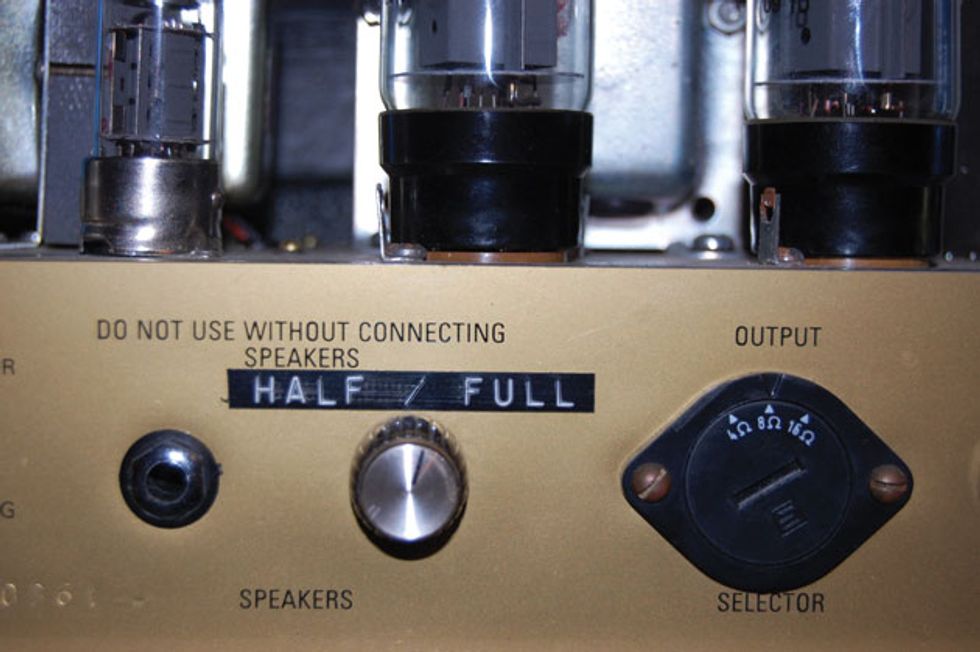
This rotary half-power switch was installed in an output jack space for minimal invasiveness and easy access,
and can be easily undone.
The first thing you'll need to do is install a DPDT (double pole/double throw) switch in the amp. This can be a toggle or rotary switch. Since this amp would probably not be used with more than one cabinet, I chose to install a rotary version in place of one of the speaker output jacks on the rear panel. No extra holes and completely reversible. One set of contacts (or pole) of the DPDT switch will be used for one side of the push-pull output stage and the other pole for the other side. The common terminal of each side will connect to the tube screen grid pin.
In the case of a typical octal tube, this will be pin 4 and will usually have a 470 ohm or 1K ohm resistor attached. Leave the resistor attached to the tube socket and disconnect whatever is connected to the other side of the resistor. This will typically be a wire coming from the B+b section of the power supply. We will be connecting this to the switch. In many amps, these screen grid resistors may be tied together with a wire or solid buss wire. In a two-output tube amp, disconnect the wire connecting the resistors. In a four-output tube amp, leave the right pair connected to each other and the left pair connected to each other and disconnect the wire in the center connecting the right pair to the left pair. Now we should be ready to wire the switch.

Fig. 1
First, connect a wire to the common terminal of one side (or pole) of the switch. Connect the other end to the screen grid resistor(s) of the right tube(s) (Fig 1). Next, connect a wire to one of the switched terminals on that same pole of the switch. Connect the other end to that same tube's plate connection (Fig 2).
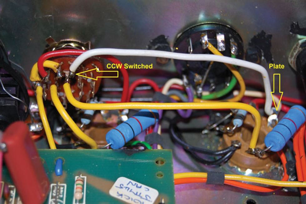
Fig. 2
On a typical octal tube, this will be pin 3. In a four-tube amp, pin 3 on both tubes will be connected with a wire. Attaching your wire to either pin 3 will be fine. Next, do the same for the other pole of the switch (Fig 3)—common to screen grid resistor(s) of the other tube(s) and the switched terminal (same position as the other side) to pin 3 of the other tube(s).
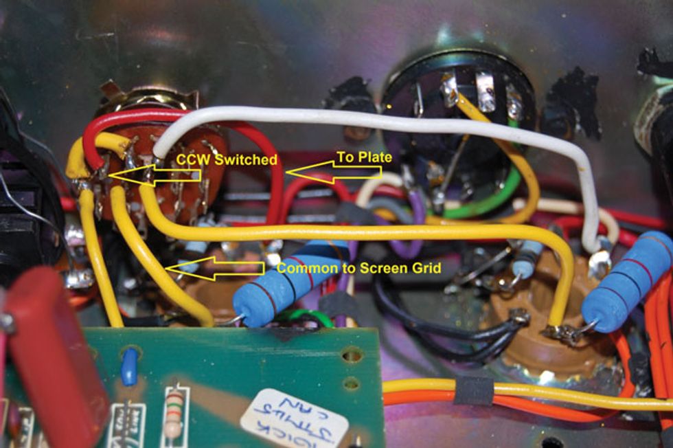
Fig. 3
This should now leave us with just two open terminals on the switch. These should both be on the same end of the switch. Connect both of these terminals together and attach them to the B+b wire that you disconnected from the screen grid resistors (Fig 4). You may need to use an extra length of wire to reach the original B+b wire, but that's okay. Just make sure the splice is insulated well.

Fig. 4
There you have it. In one switch position, the amp will be completely stock (full power pentode mode), and in the other, the output should be reduced (half-power triode mode).
Now go rock out … but more quietly.