For the past couple of months, I’ve found myself acting as bass player for a new band. It’s been a bit of a change of gears for me as I’m usually playing guitar or lap steel. In playing bass, I found myself with a need for feeding my desire for headroom—a need that can only be satiated with lots of big power tubes and stacks of speakers. I purchased an Orange AD200 bass head with their matching 4x10 and 1x15 bottoms.
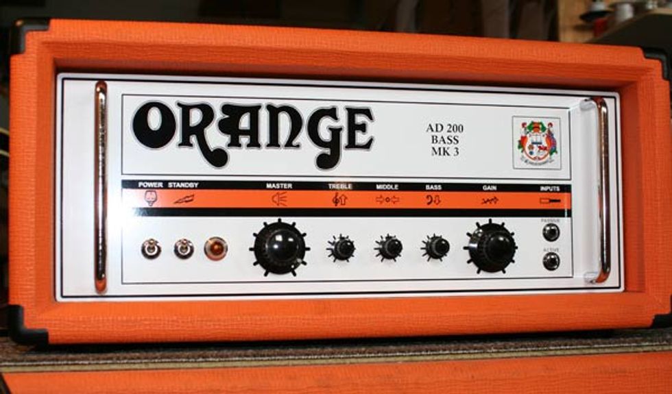
The Patient
In its stock configuration it’s a formidable rig to be sure. I was very impressed with the power, tone and range that it had to offer, even when trying to keep up with a very loud drummer. I played it joyfully for a few months and didn’t have a single complaint. What a happy and content fellow I was… Yet… I always have this little nagging voice in the back in my head saying, “what if I changed some components? Sure I’m happy now, but couldn’t I be happier?” And so it always seems to begin with the little nagging voice that I keep listening to against my better judgment. The same voice that often leaves me sitting at my bench, head in hands thinking, why did I start this project? I was so content! WHY?
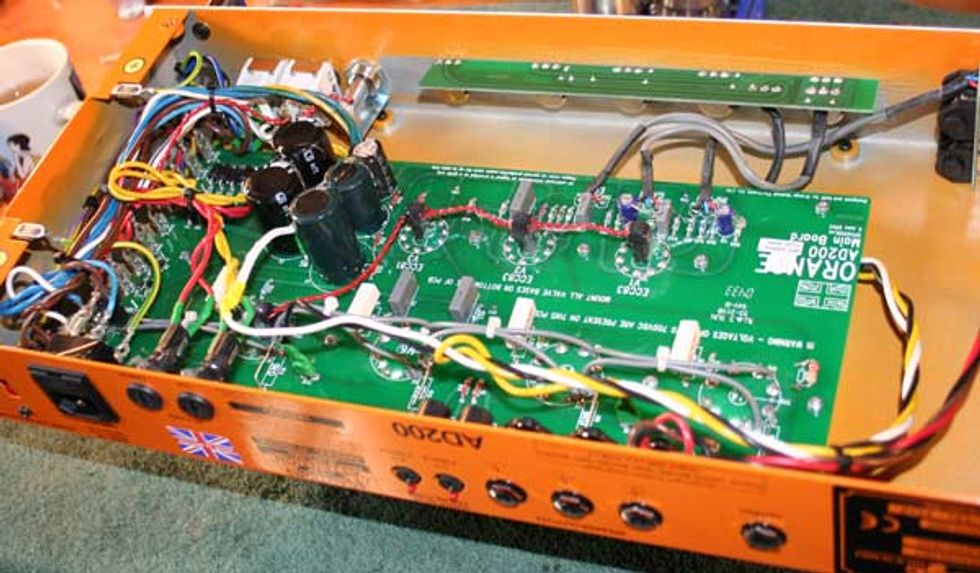
Before Gutting
The concept of changing only a few key components was quickly forgotten once I committed to this project (and had a screwdriver in hand). I gutted the amp to the bare chassis. Out came the printed circuit board (fig.2) with its board-mounted tube sockets, pots, transformers—everything.
With the chassis completely stripped, it was time to lay out, measure and drill new holes for the upgraded chassis mounted tube sockets. As the new power tube sockets needed a bit more room than the PCB mounted ones, a Dremel tool with a coarse sanding drum bit was used to enlarge the holes. Care was taken to make sure that the pin alignment made sense with the lay of the future wires before drilling the mounting holes used to bolt the sockets to the chassis. While I had the drill in hand, I also enlarged the front panel’s pot holes to accommodate the larger upgraded pots that were going to be installed. The placement for the circuit board mounting holes were also located/drilled, as was the location of the ground lugs that were going to be used in the star grounding scheme.
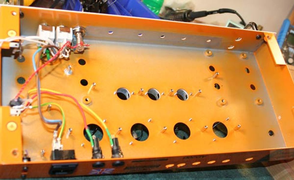
Removing the Guts
One of the most time consuming things for me when building a “one off” amp is the chassis layout. If done properly, it makes the rest of the assembly more of a connect-the-dots type of process. If done in a haphazard and incomplete way, one finds themselves drilling extra holes and routing wires in a way that may not be as professional looking or functional. In high gain designs, a poor layout can lead to excess noise and frustration.
Trying to work within a pre-existing framework is even more of a challenge. It would have been easier to start from scratch with a blank chassis, but I wanted to retain the “Orangeness” of the amp. After all, I am using the original schematic for the project, as it is a fantastic design. I just wanted to upgrade the components and make it a bit more serviceable and rugged.
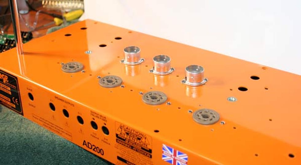
New Sockets
After mounting the tube sockets (I prefer the Micalex sockets made by Belton) it was now time to select the components to be loaded onto the circuit boards. Unfortunately, this will have to wait for the next installment. Read part 2 here.
 Tim
Schroeder is the owner, master luthier and chief designer of Schroeder
Guitar and Amplifier Repair in Chicago Illinois. There he oversees the
daily repair operations of the shop as well as designs the amplifiers
and effects that they manufacture in house.
Tim
Schroeder is the owner, master luthier and chief designer of Schroeder
Guitar and Amplifier Repair in Chicago Illinois. There he oversees the
daily repair operations of the shop as well as designs the amplifiers
and effects that they manufacture in house. schroederguitarrepair.com
312-226-9668