 |
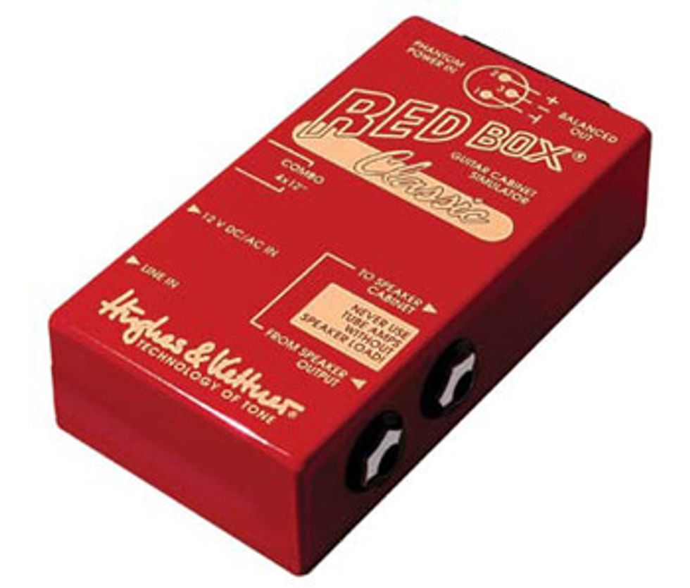
If you own an amp that doesn’t offer a line out for direct recording or sending a signal to a house mixing board, I believe that instead of modding the amp, you’d achieve much better tonal results by using a Red Box or some similar unit that you patch between the amp output and the speaker. Because these external devices have speaker-simulation circuits, they sound much better than any basic line out. And because the G40V actually has a 1/4" output from the chassis to the internal speaker, it would be very easy to connect an external box.
However, if you wish to use a line out simply to send a signal to the power section of another larger head or power amp, then a very basic line out will do the job.
Warning: Working inside an amp is very dangerous—it can even be lethal. So if you are not familiar with the inner workings of a tube amplifier and the possible hazards involved, please have this work performed by someone who is.
Click here to download a PDF of the schematic.[rebelmouse-image 25771742 original_size="640x433" expand=1]
Mount a 1/4" jack on the rear of the amp close enough to the speaker output jack that you’ll be able to install a resistor between the two jacks. Connect a 1.5k resistor to the tip connection of the speaker jack. Orient the jacks so that the other end of the resistor will connect to the tip connection of the new line-out jack. Before soldering this end to the line-out jack, install a 100 Ω resistor in parallel with a 0.1 μF capacitor between the tip and ground connections of the line-out jack. Now what you should have is the signal coming from the speaker output jack through a 1.5k resistor feeding the 100 Ω and 0.1 μF parallel network across the line-out jack. The two resistors serve as a voltage divider to reduce the signal level, and the capacitor serves to slightly attenuate some of the high-end content. Without it, this signal can sound pretty harsh. Feel free to experiment with different cap values to find something that matches your taste. Larger values will attenuate more high end and vice versa.
Next, looking at the schematic, I noticed a few other areas where you could personalize the amp with some simple mods. This is the fun part. I should note that these amps sport typical low-cost printed circuit boards, so you should be a bit careful when working on them. Since you’ll probably be turning the board over more than a few times, make some quick notes of where all the wires are attached, in case one decides to disconnect itself!
First, if you’d like to give this little piggy a bit more gain, locate the 510k resistor (R3) that attaches to the CW side of the volume pot. This resistor, along with the volume pot, forms a voltage divider, and as such prevents access to half of the signal level. You can either remove this resistor and replace it with a solid lead, or simply solder a short jumper wire across it. (The latter makes it easier to reverse this change.) This will allow access to the full output level of stage one, enabling more saturation of stage two.
If this turns out to sound too mushy on the low end, especially with humbucker-equipped guitars, you’ll need to reduce the amplification of the lower frequencies in the first stage. To do this, locate the 220 μF capacitor (C8) in parallel with the 2.7k resistor (R11) in the cathode of the first gain stage. Replace this cap with a substantially smaller value. I’d suggest values as small as 1 μF or 0.68 μF.
Now, if you need to bring a bit more fullness back into the amp, we can visit the next amplification stage. Increasing the value of the .047 μF cap (C9) in the cathode of this gain stage will cause it to amplify more low frequencies. Even increasing it to a value of 0.68 μF should make a significant difference. But hey, if you’d like to be a bit more daring and raise the full range gain level of this stage, try decreasing the value of the cathode resistor. Experiment with a 4.7k or possibly a 2.7k and see if you like the results.
Now, let’s move over to the tone stack. In looking at the schematic, I’d guess that the amp’s Treble control affects a bit more of the frequency range than it should. This would be due to the exceptionally large value of the treble capacitor in the tone stack. A 0.001 μF (1000 pF) capacitor (C12) here can make an amp sound a bit nasal. Try replacing this cap with a 470 pF, a typical value that works well in higher-gain amps. This should yield a better- sounding tone stack.
Last, let’s address the Presence control. In parallel with the Presence control is a 4.7k resistor. I’d suggest removing this from the circuit. Since the Presence pot is connected directly to ground on one side, this resistor is not needed as a DC path to ground, and removing it should noticeably increase the Presence control’s range. There is a better method for wiring this presence circuit that would require this resistor, but as always, I attempt to keep these modifications as basic as possible without altering the circuit board itself.
Now you’re ready to enjoy your rip-snortin’ little piggy. In closing, thanks to all the readers who sent me links to the Bassman 50 schematic I was searching for [“Rockin’ a Bassman 50,” May 2011]. I appreciate it!
 Jeff Bober is one of
the godfathers of the
low-wattage amp revolution,
co-founded and was
the principal designer for
Budda Amplification. Jeff recently launched EAST
Amplification, and he can be reached at
pgampman@gmail.com.
Jeff Bober is one of
the godfathers of the
low-wattage amp revolution,
co-founded and was
the principal designer for
Budda Amplification. Jeff recently launched EAST
Amplification, and he can be reached at
pgampman@gmail.com.