Now that we've analyzed the Telecaster “dark circuit" that Fender used from mid 1952 up to late 1967 [“Factory Telecaster Wirings, Pt. 1," August 2013], it's time to explore the Tele wiring that was introduced after 1967. This wiring is referred to as the “modern" or “standard" Telecaster wiring and is still in use today.
To understand why Tele wiring changed in 1967, it's useful to review some history. Leo Fender had suffered from a strep infection since the mid '50s, and in February 1965, he sold Fender to the CBS group because he thought he was seriously ill and felt he could no longer lead the company. (Ironically, he changed doctors shortly after the CBS sale and was cured.)
The $13 million CBS paid for Fender was more than spectacular at that time. As part of this deal, Leo signed a non-compete clause and remained a consultant with Fender for the next two years. In retrospect, three factors led to the change in the Telecaster wiring in late 1967: The first was customer demand to abandon the bassy neck-pickup preset. Second, once Leo quit CBS and lost his consultant status, he could no longer insist on keeping his '50s circuit untouched.
Finally, CBS was known for their cost-cutting policies. The redesigned wiring was easier to produce than its predecessor and used only one capacitor instead of two. In the '60s, capacitors were much more expensive than they are today, and given Fender's enormous output at that time, this yielded a huge cost saving for CBS.
After 17 years of existence, the neck pickup preset vanished and a new wiring that provided a more traditional dual-pickup switching was adopted. This old neck preset is mostly forgotten today because in the past, many players clipped off the 0.1 µF preset cap and installed a much smaller value for some warm rhythm playing. Other guitarists simply rewired the whole circuit to their individual needs, and consequently some experts credit Leo as the inadvertent godfather of the guitar-modding scene. Here's the switching matrix of the post-'67 wiring:
Position #1 (switch lever on the right): Bridge pickup alone with tone control engaged.
Position #2 (switch lever in the middle): Both pickups together in parallel.
Position #3 (switch lever on the left): Neck pickup alone with tone control engaged.
Electronically, the original post-'67 wiring featured the following components: Two 250k audio pots from Stackpole or CTS, a 0.05 µF/50V ceramic disc cap (aka “red dime") with SK imprint, a 1000 pF (0.001 µF) treble bypass cap from Cornell Dubilier (aka “circle D"), and a 3-way pickup selector switch with the 1452 imprint from CRL.
The small 1000 pF cap was soldered as a treble bypass cap between the input and the output of the volume pot to keep the high-end alive when rolling back the volume. This cap is not shown in the circuit drawing and is no longer used today. The idea behind it was good, but 1000 pF was way too much and only a good choice for funk or reggae players, because it offered high-end galore but almost no bass. The absence of a resistor in parallel to the cap transformed the treble bypass cap into a treble bleed network, and it influenced the taper of the volume pot in a bad way—another downside of this design.
For all wire-runs from the pickups, and to and from the switch and pots, Fender used a waxed cloth wire in black and white, skipping yellow as a third color. Black was for all ground connections, white for the hot wires from the pickups, as well as all connections between the switch and the pots.
Fig. 1 shows the post-'67 wiring scheme. Note that the tone cap wiring shown here is not the way it was done in the Fender factory—instead, it contains a modern, useful twist. Originally, the leg of the cap connected to ground was soldered to the outer leg of the volume pot that's soldered to ground. Electronically, this is completely identical, but it's easier to solder the tone cap as shown in this diagram, and you don't have to worry about insulating the legs of the tone cap to prevent an accidental short.
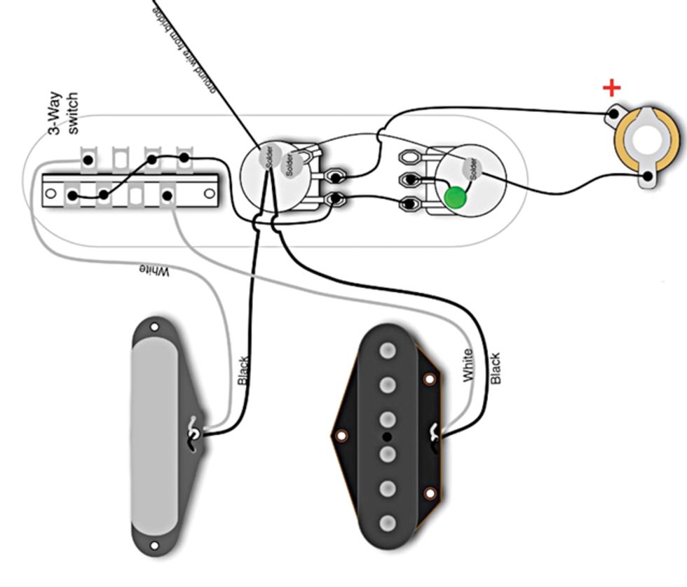 The post-1967 Telecaster wiring that's still standard today. Diagram courtesy of Seymour Duncan and used by permission.
When using very large tone caps, like tubular shaped paper-waxed caps, paper-in-oil caps, or the all-time favorite Orange Drops, it may be necessary to use the original Fender factory approach because placing such big caps on the bottom of the tone pot can cause space problems. The bottom of the cavity may not be routed deep enough to accommodate the pot when a large cap is soldered to it, so please keep this in mind when using large tone caps. Placing them between the two pots will avoid such issues.
Here's how the post-1967 Telecaster circuit evolved over the years: In late 1968, the waxed cloth wire was replaced by stranded, plastic-insulated wire, and green was introduced as a new third color.
In 1969, both 250k pots were replaced by 1Meg pots to add even more highs. In late 1981, the tone pot converted back to 250k, and the volume pot followed in late 1987. The 0.05 µF tone cap was replaced with a less bassy 0.022 µF cap in 1983. Until 1982, Fender used different types of ceramic caps with a 50V or 100V voltage rating, followed by Mylar (aka “blue molded") caps Fender first used in their humbucker-equipped guitars in the early '70s. In 1987, the 1000 pF treble bypass cap was removed from the circuit. After 1981, Fender used different brands of 3-way selector switches, all of them without the 1452 imprint.
Next month we'll take a closer look at our new buddy, the Telecaster 3-way pickup selector switch. Understanding the basics of this switch is essential to develop your own custom wirings. Until then, keep on modding!

![Rig Rundown: The Black Crowes’ Rich Robinson [2026]](https://www.premierguitar.com/media-library/youtube.jpg?id=66952027&width=1245&height=700&quality=70&coordinates=0%2C0%2C0%2C0)