Last month, we started
discussing 5-way switches
that offer more wiring possibilities
than the standard-issue
Strat unit we all know so well
[“Introducing Fender's 5-Way Super Switch," September 2011]. Ready to explore the
technical aspects of this beautiful
beast? This is where the fun
really starts!
I'll keep it as simple as possible
because the switching
matrix of this device is much
more complex than it seems.
I'll guide you step-by-step
through all five switching positions
and show you which lugs
are active and connected to
each other in each position.
Let's recap the essential
points: The 5-way super switch
is not simply two standard
5-way switches in one package.
Nope, there's more—lots
more: Instead of two stages of
the normal 5-way switch, this
switch offers four completely
independent stages with six terminals
each, so we have a total
of 24 terminals. Here's another
way to look at this: We have
six lugs on each stage, rather
than the five that are on the
standard 5-way switch.
To simplify things, we can
say that each stage has five
input lugs and one output lug
(aka “common"). Keep in mind
that all four stages are completely
independent from each
other, but they all switch at
the same time! So if you want
to combine two or more stages
for a special wiring, you need
to connect them with a short
jumper wire.
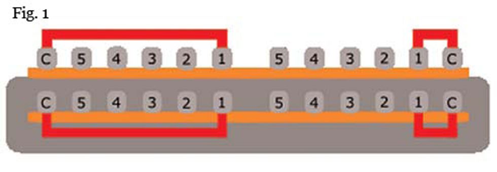
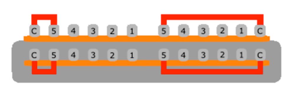
Fig. 1 illustrates what
this super switch is doing in
position #1. This would correspond
to the bridge pickup
alone on a normal 5-way
switch. In these diagrams, “C"
is short for “common." You can
see that in this position, input
lug #1 is connected to the corresponding
output lug—C—of
all four stages.
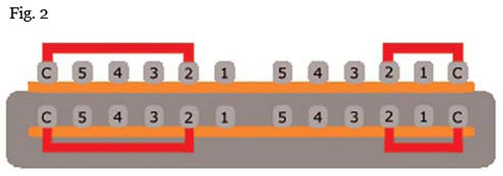
Look at Fig. 2 to see what's
happening at position #2,
which corresponds to the
bridge and middle pickups
connected together in parallel
on a normal 5-way switch.
We're following the same
principle as before: On all four
stages, input lug #2 is now
connected to the C output lug.
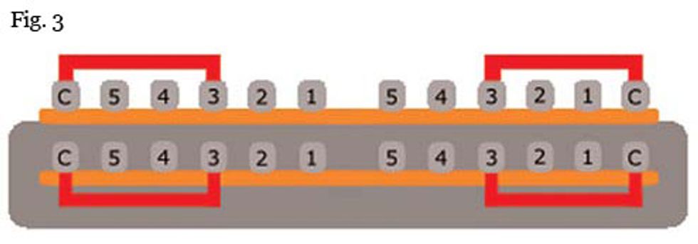
I think you've got the working
principle of the switch
now. Fig. 3 shows position #3,
which would be the middle
pickup alone on a standard
5-way switch.
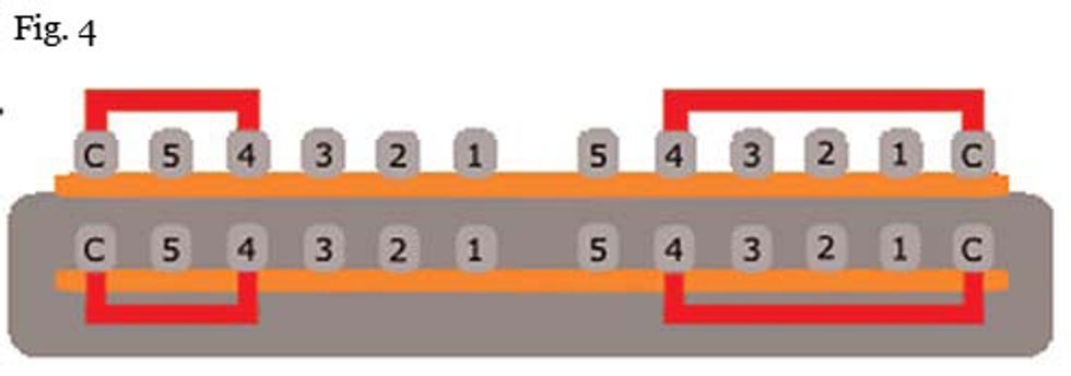
And position #4 (middle
plus neck pickup wired in parallel
on a normal 5-way switch)
is shown in Fig. 4.
And finally, Fig. 5 reveals
how position #5 is configured.
On a normal 5-way switch,
this would select the neck
pickup alone.
All right! That's the basic
principle of the 5-way super
switch. You can spend hours
developing your own custom
wiring using this device to
implement all kinds of gimmicks
like out-of-phase,
series/parallel, and countless
other options.
To get a sense of how complex
wiring schemes can get
with a super switch, go to the
Fender website and look at
the various “Fat Strat" wiring
Exploring Fender's 5-way Super Switch BY DIRK Wacker
diagrams. These schemes can
make a great starting point for
your own custom variations.
Thanks to our friend
Bartek from the Guitar Wiring
Blog (guitarwiring.blogspot.com) for granting us permission
to use his great diagrams
in this column.
Stay tuned for more Strat
mods coming next month,
when we'll return to more
practical mods after all the
switching theory we've covered
in the last few columns. Next
up: Wiring a “tone switch" for
your guitar. Until then, keep
on modding!

Dirk Wacker lives in
Germany and is fascinated
by anything related to old
Fender guitars and amps.
He plays country, rockabilly,
and surf music in two
bands, works regularly as a
session musician for a local studio, and writes
for several guitar mags. He's also a hardcore
guitar and amp DIY-er who runs an extensive
website—singlecoil.com—on the subject.


![Rig Rundown: The Black Crowes’ Rich Robinson [2026]](https://www.premierguitar.com/media-library/youtube.jpg?id=66952027&width=1245&height=700&quality=70&coordinates=0%2C0%2C0%2C0)