Hi Jeff,
I need to refurbish an ’86 Fender Concert that has been sitting idle for 10 years. I replaced the original speaker with a Celestion G65 and would like to put in a 30-watt Celestion G12H(55). I’d also like to replace capacitors and resistors to add a little Marshall bite to this old amp. (My ideal sound would be a JTM45 plexi, but I can’t afford one right now.) I usually have such work done by a professional repairman. Do you have any suggestions for him?
Thanks,
Tony Martinez
Hi Tony,
My first thought was there’s no way to get your Concert even remotely close to a JTM45—the amps are just too different. But if we disregard the gain channel and focus on the normal channel, we probably can get the voicing closer to that of a JTM45. The JTM45—like standard four-input 50- and 100-watt Marshalls—is basically a clean amp, with most of its distortion characteristics coming from overdriving the output stage.
There’s not a lot of front-end gain, much like the normal channel of your Fender. The gain structure of the two amps is rather similar, even though your Fender’s normal channel has an extra gain stage. (This stage is necessary as a mixer for a reduced dry signal and the reverb return signal, and it is not used to generate overdrive.)
There are still many differences between these two amps: One has reverb, and one doesn’t. One has the tone stack after the first gain stage, and the other after the second stage. One uses a cathode follower-driven tone stack, the other a plate-driven stack.
And they have different transformers, which can also make a big difference. Still, let’s see if we can get your Concert closer to your preference.
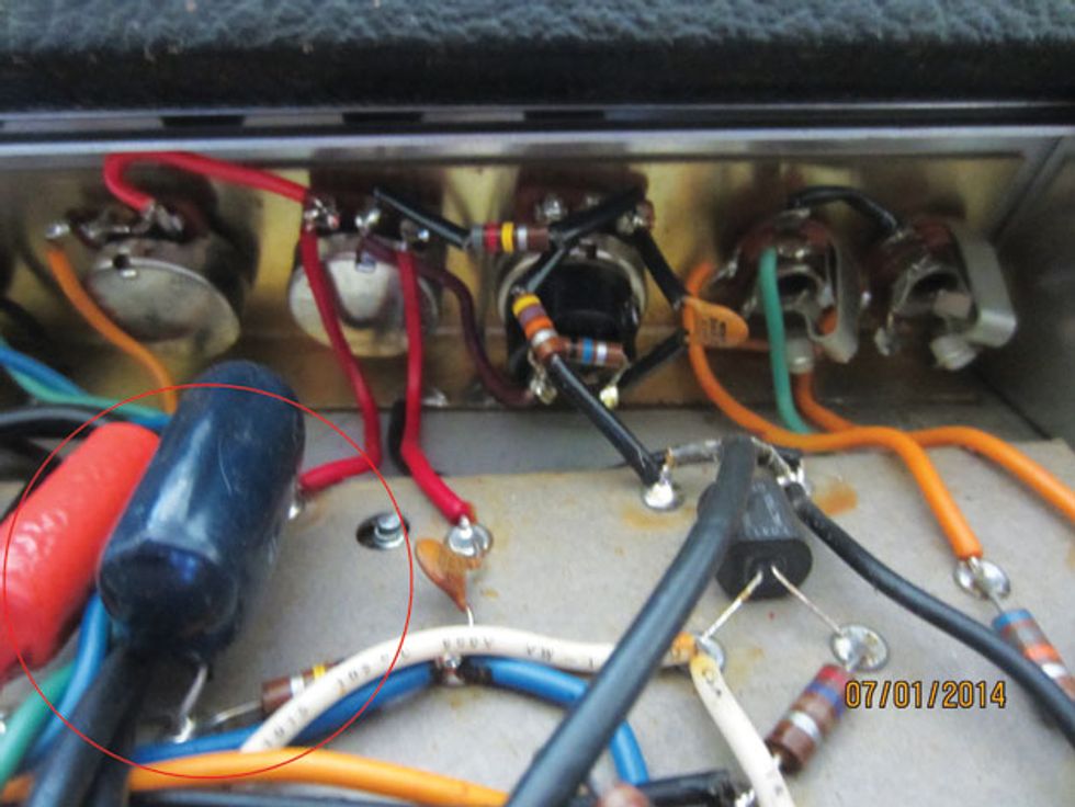
Changing these tone stack capacitors adds Marshall-like midrange.
Let’s start with changing a few things in the tone stack (Photo 1), starting with the capacitors. A standard Fender tone stack uses 0.1 µF and 0.047 µF capacitors. Remove these and install two 0.022 µF/600V caps. This adds midrange content, which Fenders seem to lack (not necessarily a bad thing). By the way, you’ll find these 0.022 µF caps in my very favorite Fender, the Super Reverb.
Next, we’ll change the slope resistor from a 100k to a 56k. This alters the signal balance between the treble and mid/bass sections. The Concert amp does not have a mid control, but if you feel a need for more or less mids after you’ve done the modifications, you can always change the value of the 6.8k resistor connected to the bass pot. This resistor approximates a setting of 6 or so on what would normally be a 10k control, but you can install any value between zero and 25k to set the mids. Hey, you can even install a 10k or 25k pot in the front panel’s #2 input if you really want to get creative!
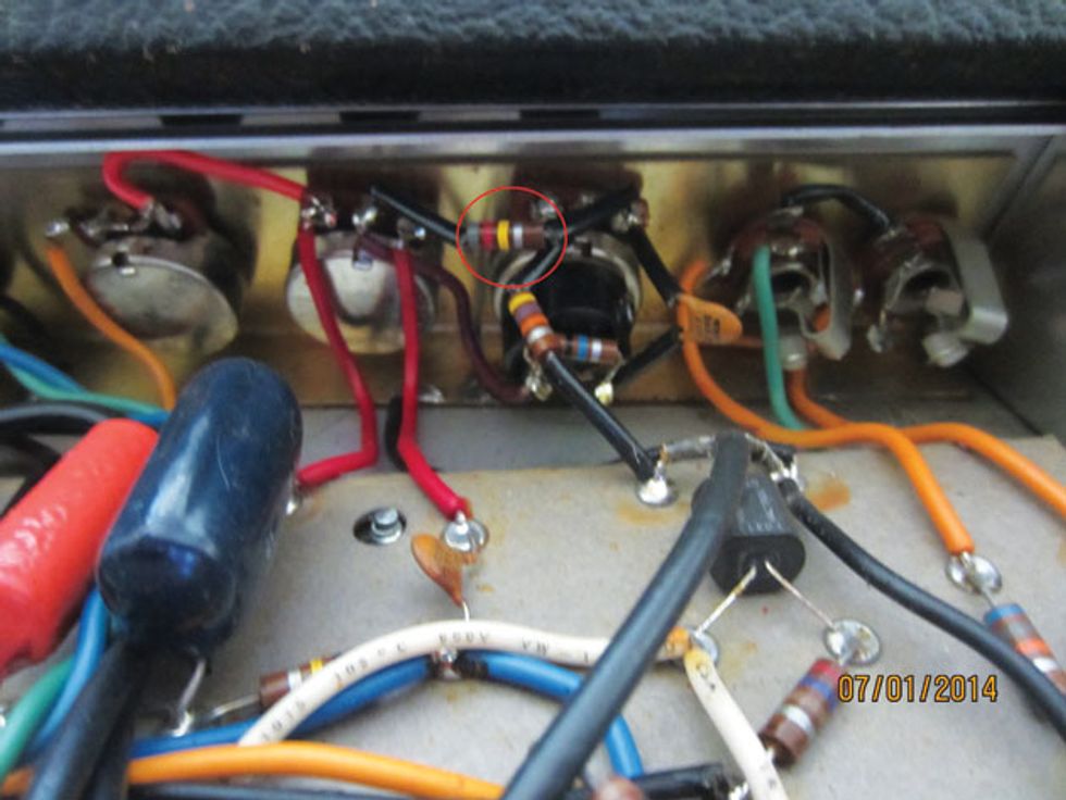
Photo 2: Altering this resistor produces a stronger, more overdriven signal.
Also, you’ll find an 820k resistor between the treble pot wiper (center terminal) and the volume pot (Photo 2). Let’s change this to a 470k resistor, a typical value for the mixing resistor for the two channels in a JTM45. This sends a stronger signal into the next stage of the amp. If you decide you’d like even more drive, lower this value to 270k, the value found in early JTM45 models. This part of the circuit also includes a bright switch—that’s handy. In the off position, the circuit resembles the normal channel of a 45. When the bright switch is engaged, it adds a bright cap like the one found in a JTM’s bright channel. And while we’re in this area of the circuit, let’s remove the 25 µF cathode bypass capacitor on V2b and replace the 1.5k resistor with a 680 ?. These values, typical for the second gain stage of a 45, prevent an overabundance of low frequencies, which tend to make things a bit mushy and lessen the amp’s articulation.
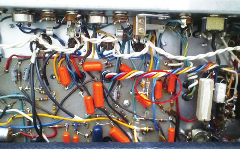
Photo 3: Modifying the phase-invertor portion of the circuit opens up the amp’s sound.
Finally, let’s modify the phase-inverter circuit (Photo 3), which tends to open up the amp’s sound and feel. V7 is the phase inverter, which uses two 330k grid resistors. Replace these with 1M resistors. You’ll also find a 680 ? cathode resistor. Replace it with a 470 ?. Attached to it is a 6.8k. Replace that with a 10k. Next, the output caps: On pins 1 and 6 of V7 you’ll find 0.01 µF caps. Replacing these with 0.1 µF 600V caps drives the output tubes with a much fuller signal.
These mods should get your amp closer to your JTM45 ideal. Some of these changes affect the amp’s drive channel, but my guess is you’ll be using its normal channel with some great pedals, just as you would with a real JTM45.
WARNING: All tube amplifiers contain lethal voltages. The most dangerous voltages are stored in electrolytic capacitors, even after the amp has been unplugged from the wall. Before you touch anything inside the amp chassis, it’s imperative that these capacitors are discharged. If you are unsure of this procedure, consult your local amp tech.