pedal problem broken issue noisy noise hum solder effect stompbox troubleshooting faq

How to troubleshoot a noisy or troublesome pedal

Hey pedal-heads, welcome back to Stomp School. This month, we’ll wrap up our troubleshooting and maintenance series with some more advanced tips for solving your pedal problems. In part one of our troubleshooting discussion, we suggested taking a noisy or troublesome pedal out of your rig to deal with it later. Now we’re going to deal with it.

If the pedal is passing signal and works properly, but seems unusually noisy, there are a number of things that could be causing the problem. First, check the power supply. Using the wrong power supply can cause noise and hum, and can damage your pedal. A generic power supply like you find at Radio Shack should never be used with pedals. You need one designed for effects, one that is both regulated (voltage does not
drift) and filtered (no noise from the AC line). If the pedal runs at 9 volts, try testing it with a battery.

After you’ve confirmed the power supply as the cause, you can look at the pedal itself. When testing a pedal for noise, set the volume knob for unity gain (the volume is the same whether the pedal is on or off). Turning the volume up will amplify any noise that’s already there, making it more apparent. If you turn your guitar volume all the way down, you can hear what’s actually coming from the pedal. A slight white noise is normal on many pedals when set at unity gain. If you are hearing excessive noise from your pedal when it’s not boosting your signal, try to determine what sort of noise it is.

Humming noise is a low frequency, consistent hum, like you hear when playing a guitar with single coil pickups near electronics. This usually comes from AC power leaking into your signal somewhere, or it could be your guitar pickups. Try a guitar with humbucking pickups to make sure the noise is actually coming from the pedal and not the guitar. Hum can also come from a bad ground, like the sound you hear when you pull the cord out of your guitar.

Static noise is an inconsistent crackling, like a bad cable or guitar jack would make, which is often caused by a loose connection in the pedal—in one of the jacks, wires or the switch. It can also be caused by a very sick component (transistor, e.g.).

White noise, a sort of a hissing sound, is another common type. Most pedals will have some, but excessive white noise could be due to some bad electronic components or a need for calibration. The last common type of noise is a high-pitched squealing sound. This can be caused by feedback oscillations in the pedal due to poor wiring layout—wires should not be in neat parallel lines, like those found in some boutique pedals. In analog delay pedals and others with BBD chips (chorus, flangers, etc), squealing can be caused by poor calibration.

Open up the pedal while it’s still plugged into the guitar and amp, leaving the volume on the guitar all the way down. Probe the inside of the pedal with some non-conductive device to see if you can locate the source of the noise. It could be a bad solder joint, failing switch contact, faulty connections with a jack or pot, or it could be a faulty component on the board. Try wiggling the battery clip to see if that causes any noise. You can also try to re-route the wires to stop some noises, like whistling. Unfortunately with most mass-produced pedals made these days, there is nothing you can really do inside: everything is directly soldered to the board, no hand wiring, and using proprietary parts that can’t be replaced. When one of these pedals dies past the warranty, you’re probably holding a paperweight.

Many problems, especially on older pedals, are caused by poor solder joints. This problem may be getting worse, as most builders are being forced to use lead-free solder for European RoHS. If you can wiggle a wire or component, and the lead moves on the attachment point, the joint is very bad and needs to be redone. The best repair is to de-solder it and redo it with fresh solder. If you don’t have de-soldering tools, touching it up with a little new solder usually does the trick. (There’s a great tutorial called “how and why to solder correctly” on YouTube.) Often the solder joint is not physically loose but will be dull and chalky—another sign of a bad joint. Intermittent sound, and noise caused by poor solder joints, can often be exposed by gently twisting the circuit board. If twisting the board cuts the signal on and off, there is probably a bad joint somewhere.

Noise is relative, so you may want to compare your noisy pedal to a similar one (there’s a reason some people call them noise toys). If there is definitely a problem but you just can’t figure it out, it’s time for professional help. If the warranty is still valid, that’s your best bet. Otherwise, see if you can find a qualified local repairman to bring it to. Often the problem will disappear when your effect is tested by a tech, like about half of all pedals we get in for repairs. Maybe they just like getting out of the house.

Check back with us next month. Until then, keep on stompin’!

Read MoreShow less

Mods that will take your MXR Distortion Plus to a bigger, meaner level

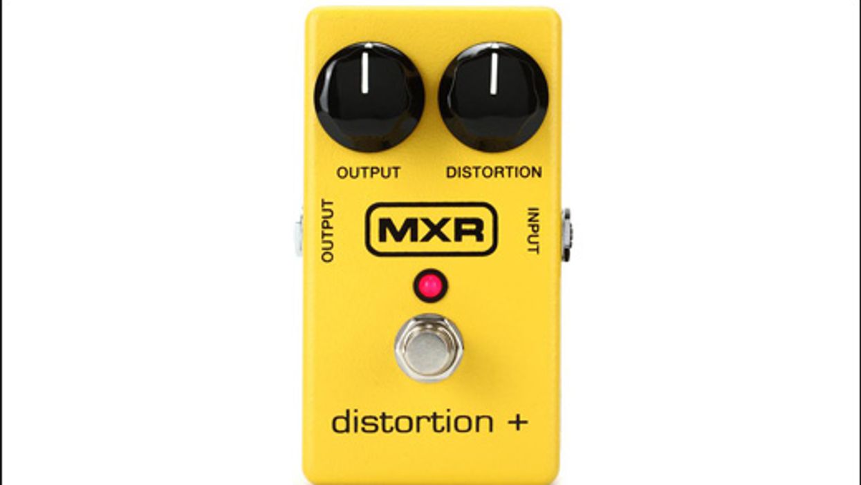
Many years ago distortion pedals were much more limited than they are today. MXR released a simple hard clipping device called the “Distortion Plus” in the late seventies. Randy Rhoads, among others, used this pedal to achieve more distortion in his amps. Guitarists everywhere mistakenly thought that this little device was the secret to Randy’s tone. Since then, there have been many, many different versions of this type of circuit. Let’s take a look at it a bit closer; there are a great many mods that can be done to turn it into a tone monster.

Here''s the stock circuit:


The signal enters where C1 and C2 intersect. C1 is a low pass filter, throwing some highs to ground pre-clipping. C2 allows mainly mids and highs through into the clipping section. The R1 limits the signal going into the opamp and R5 sets bias for the opamp.

R4, C3, R2, and R3 control the gain and frequencies getting boosted and clipped in a traditional “non-inverting” method of opamp circuit. R3 is labeled as a gain control, however you’ll notice that it changes the tonality depending on its setting. This is because it is changing the frequency response of the opamp at the same time. With the gain control all the way up it only clips frequencies 723hz and higher, though it is at max gain. In its minimum gain setting it is boosting and clipping almost all frequencies (3.4hz and higher) though it has much less gain. This is why it sounds muddy and undefined when the the gain is lower and why it thins out when you turn the gain up.

After the signal is boosted it exits through C4 and then through R6. D1 and D2 clip the signal using a “hard clipping” method while C5 works with R6 as a low pass filter to filter out 6db worth of frequencies 15.9khz and above, which the human ear can’t really distinguish too much. Most likely this was to filter out some odd harmonic overtones and/or noise. A much better use would be to wire a 100k pot in series with a .0022uF cap in place of C5. This will act as a tone control.

D1 and D2 are 1n34a type Germanium diodes in the stock version. This leads itself to a bit of a fuzzy compressed tone with not much volume left over after being clipped.

The signal exits via the 10k pot on the output.

The Dod OD250 and YJM308 circuits are almost identical to this and these mods will work for these pedals as well.

Here some of my favorite mods that I like to make to this type of circuit:

  • Use an SPST switch to insert a .01uf cap in parallel with a .001uf cap in place of C2. This will give a ''more/less compression'' type of function, or a ''smooth/open'' tonality. For a more dramatic effect, make the .01uf a .047uf or so.
  • Add an SPST switch around C3 to add more bass by adding a .33uf cap in parallel with C3.
  • Change R2 and C3 to a 1k/.22uf for the same high gain frequency response but more gain potential
  • Change R4 to a 1m audio taper pot for better response through gain adjustment.
  • Add an SPST switch to add in diodes in parallel with R4. I have 1n34a and 1n4001 diodes shown here, though any can be used.
  • Change D1 and D2 to 1n34a and 1n4001 diodes (in series) in place of each stock diode for louder output as well as better dynamics.
  • Change C5 to a .0022uf and wired in series with a 1m audio taper pot to act as a tone control.
Here''s the schematic with the mods in place:

These mods will make your pedal into a much bigger, fuller, nicer (or meaner) sounding distortion or overdrive. While not all of the mods are necessary, I encourage you to experiment to find what you like and don’t like and tailor your own pedal to your needs.

Happy Soldering!

Read MoreShow less