This month, I felt like taking a little dive into circuits for you solder-breathers out there.
There are two main ways that diode clippers work, and there are subtle but important differences in the two ways. In the electronic sense, diodes are used as one-way valves for current. The arrow in the diode’s schematic symbol is the anode, or positive terminal, and the bar is the cathode, or negative terminal. A voltage that is more positive on the anode side than the cathode side lets current through in the direction of the arrow. When the diode is reverse biased (the cathode is more positive than the anode), then the diode blocks current from flowing, as shown in Figure 1.
In real diodes, you don’t get that one-way valve stuff for free. The price is that there must be some voltage lost across the diode, even in the forward direction, before the diode will begin to conduct. This forward voltage is different for different kinds of diodes. For silicon diodes, it’s about 0.5- 0.7V, for germanium about 0.2-0.3V, and for LEDs, it can be 1.5V–3V or more.
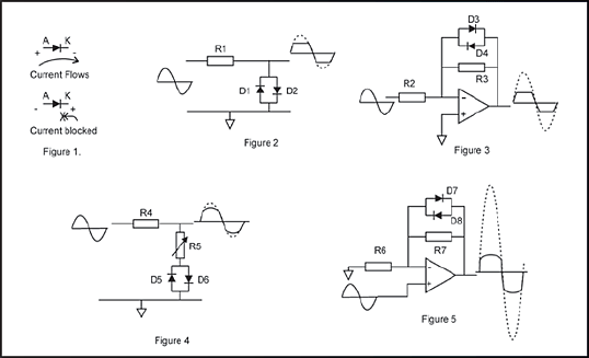
If I force a signal through a resistor, then place a pair of diodes from the end of the resistor to ground (as shown in Figure 2), the diodes will do nothing to the signal until it is more positive than D2’s forward “penalty” voltage, and again nothing until it is more negative than D1’s conduction voltage. At voltages bigger than the diode voltage, one or the other of the diodes will conduct heavily, and any greater signal level will be clipped off the top and bottom. This kind of clipping is fairly abrupt, and gives a ‘60s kind of fuzz all by itself. The MXR Distortion Plus and the Armstrong Blue Clipper, among others, used this kind of clipping.
A slightly more sophisticated way to use diode clippers is in the feedback loop of an opamp, as shown in Figure 3. This works differently from Figure 2. The opamp forces a current equal to the current through input resistor R2 to flow from its output to its negative input through R3. The diodes have the output voltage across them, but only start conducting when the output voltage of the op-amp gets more positive or more negative than the diode voltages. After that output voltage size, the diodes conduct all the output current back to the input. This is a more “delicate” way to run the diodes in clipping, and this results in a softer-sound.
You can modify the resistor-diode clipping from Figure 1 as shown in Figure 4 by putting another resistor (R5) between the original resistor (R4) and clipping diodes. This resistor causes some of the original signal to be mixed with the clipped diode signal and adds some soft-sounding roundness to the output. Representative values for R4 and R5 are 10K fixed and 10K variable. It’s a fun mod for the Distortion Plus.
The final circuit in Figure 5 shows the feedback clipper of Figure 3 but with the signal applied to the non-inverting (+) input of the opamp. This forces the op-amp to add the input signal to the feedback-multiplied signal. So the output consists of a 50/50 mix of the input and the multiplied-and-diode clipped signal, and the clipping harmonics are effectively cut in half. You may already have recognized it – this is the circuit for the clipping stage of the Ibanez Tube Screamer.
The diode clipping circuit in either the resistor-diode or feedback-diode forms is highly flexible and modifiable. If you experiment with these circuits, play with both identical diodes and non-identical diodes. Changing from, say, 1N4148 to 1N4007, or even one of each may not make much difference. Using one silicon 1N4148 and one or two germanium 1N34s will provide a subtle change in the tone of the distortion. Using one silicon diode and one LED makes a much more obvious change in tone.
Like making stew, making a good diode clipper requires some thought, some good ingredients, and some tasting as you go along. If you like cooking your own clippers, be sure to try some of these recipes.
R.G. Keen
Cheif Engineer
Visual Sound
www.visualsound.net




![Rig Rundown: John 5 [2026]](https://www.premierguitar.com/media-library/youtube.jpg?id=62681883&width=1245&height=700&quality=70&coordinates=0%2C45%2C0%2C45)




 This Episode Brought to You By: www.premierguitar.com