
Building stompboxes from scratch is easier than you might expect. So is customizing the circuits to suit your style and taste. This project walks you through the process step by step. When you're done, you'll have a killer distortion pedal—and enough knowledge about using and choosing stompbox components to build countless other pedals.
Anyone of average intelligence with functional hands and eyes can complete this project. But there are many steps—more than we can cover in a conventional magazine article. So we've created an illustrated build guide in PDF form, which you must download to complete the project.
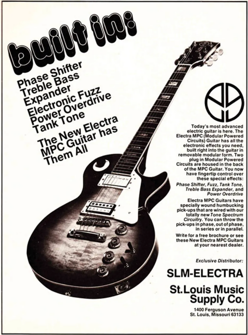
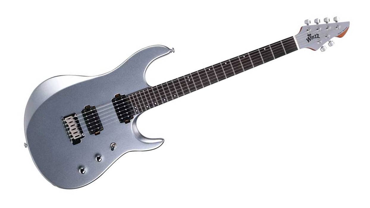
Photo 1: The Electra MPC, a late-'70s/early-'80s guitar with built-in effects, has been largely forgotten. But many boutique builders have borrowed its simple yet great-sounding distortion circuit.
What you'll build. This project is a modernized and tweaked version of a distortion circuit that originally appeared in Electra's MPC (Modular Powered Circuits) guitar, a Japanese axe with built-in effects that was imported into the U.S. by Saint Louis Music in the late '70s and early '80s (Photo 1). The guitar was never very popular, but at some point savvy boutique stompbox builders realized that despite (or maybe because of) the circuit's simplicity, it offers terrific overdrive tones. It's a fine alternative to the Tube Screamer-influenced designs found in perhaps 90 percent of today's overdrive pedals.
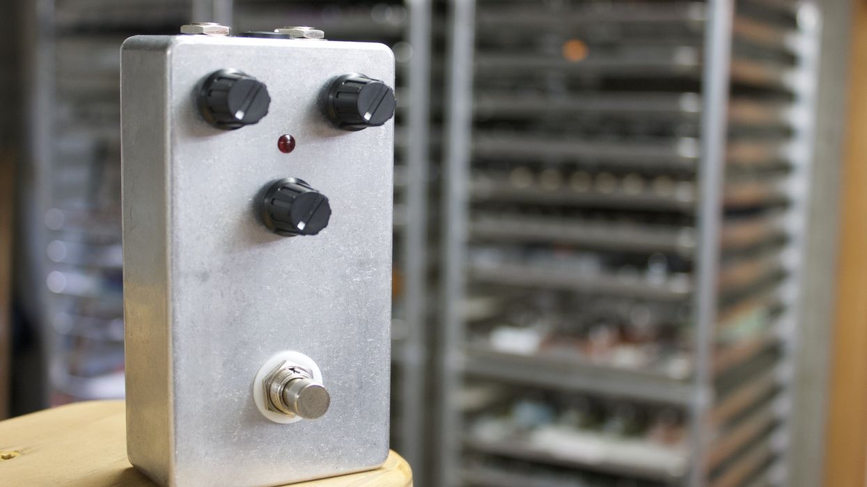
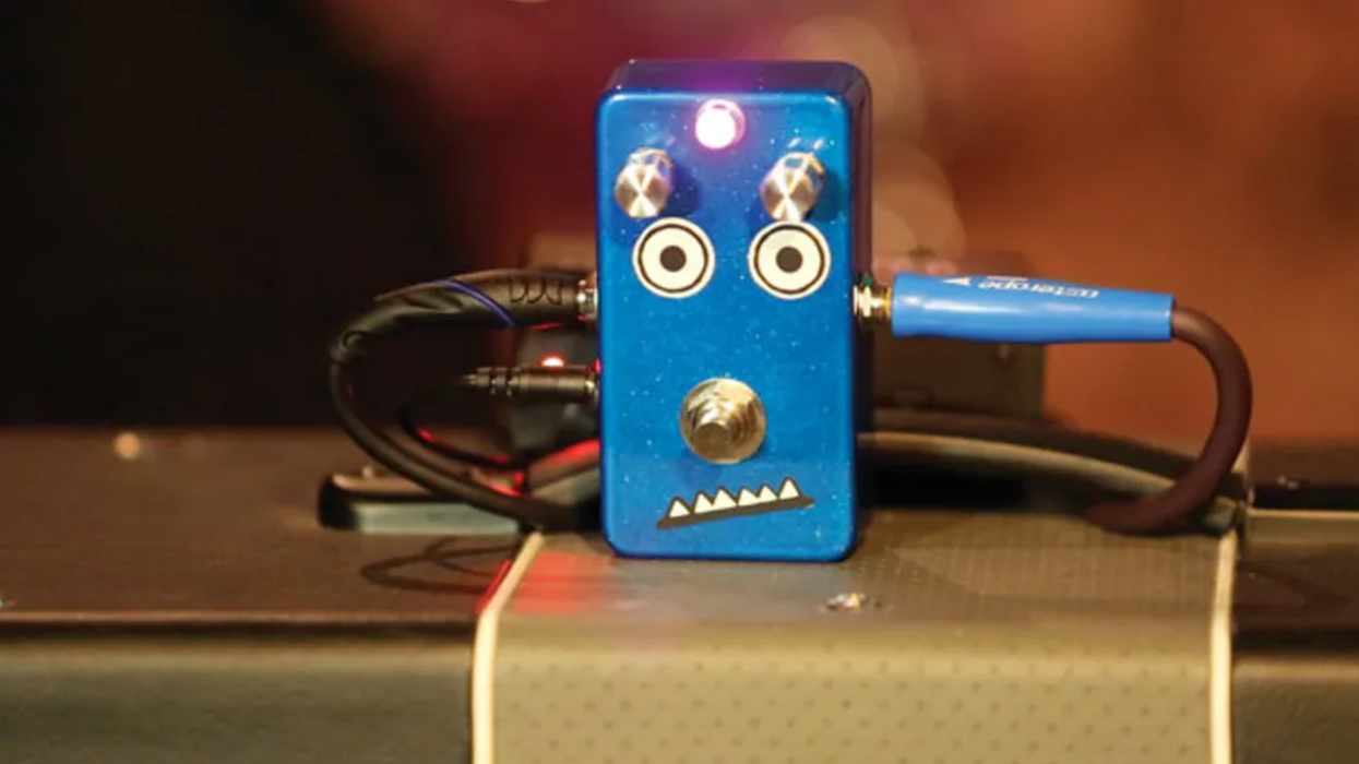
We're calling our Electra variation the PG Distortion (Photo 2). Compared to a Screamer, the PG Distortion is less compressed, less midrange-heavy, and more responsive to variations in your playing dynamics. It preserves note attack and has an edgy grind that cuts through onstage and in a mix. It's been used in several highly regarded boutique pedals (just Google the phrase "based on Electra distortion").
What you'll learn. The circuit's simplicity makes this a perfect starter project. But the goal isn't just to build a cool pedal from a few modestly priced parts. From the very first steps, you'll make design choices to suit your style and taste. You'll learn how common stompbox components work, and how to choose the right ones for your needs. Making stuff you like is a prime motive for DIY.
Now, if your goal is simply to build a cool pedal as quickly and cheaply as possible, you might consider a prefab DIY kit rather than this project. (I'm especially fond of kits from Build Your Own Clone because of their clever designs and excellent documentation.) But usually, kits like that only tell you the next step—not why you're doing the step, or how you can apply the procedure to future builds. Also, kits usually come with a printed circuit board (PCB) for mounting components, while we will make connections manually using a blank piece of perforated circuit board—a more laborious process, but a more informative one. So think of this as a stompbox-building class, with the PG Distortion as our case study.
Watch the Video Demo of the PG Distortion:
Project overview. The project is organized into five parts:
1. Preparations. Here you assemble all the needed tools and round up your parts.
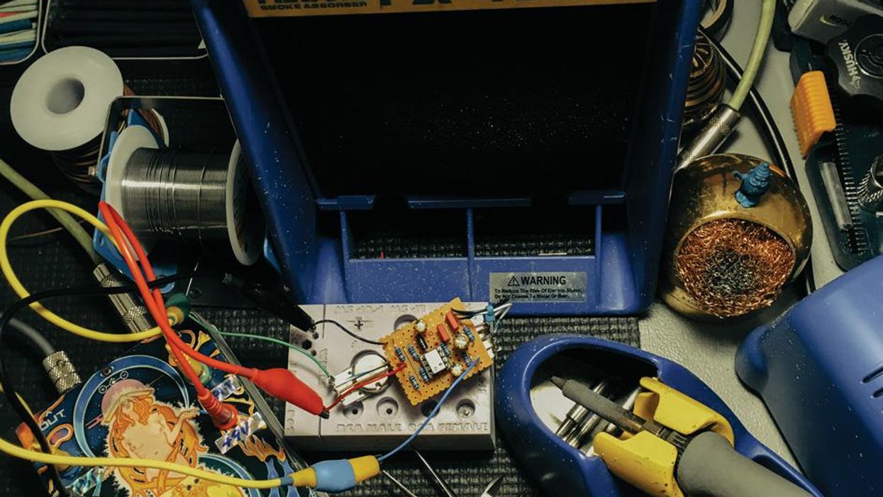
2. Breadboarding the circuit. You'll assemble the circuit on electronics "breadboard"—an inexpensive prototyping tool that lets you create circuits without soldering. This method makes it easy to understand which components accomplish what (Photo 5).
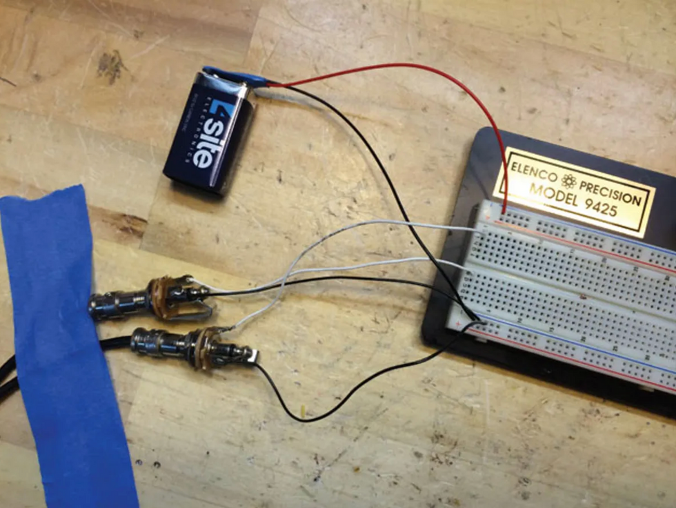
Photo 5 — An electronics breadboard lets you test and customize circuits without soldering.
3. Customizing the circuit. Breadboarding is also a great way to explore design options, which you'll do right from the beginning.
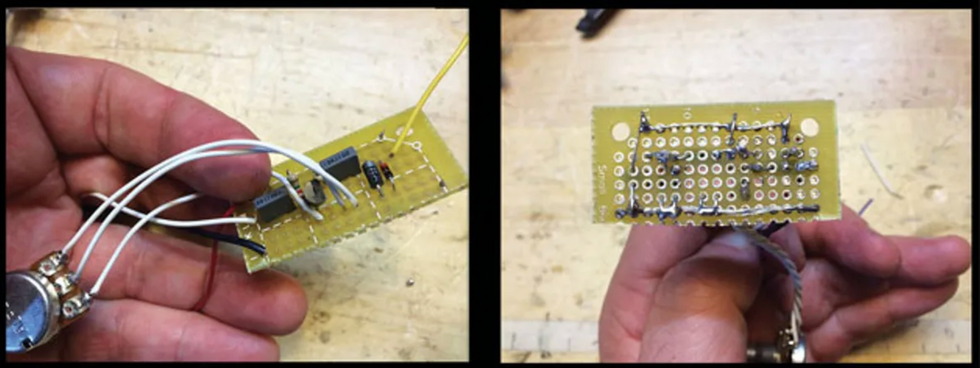
Photo 6 — After refining your circuit on the breadboard, you'll mount the components on a piece of perforated circuit board, soldering everything together on the board's reverse side.
4. Assembling the circuit on perf board. Once you finalize your design, you'll solder it onto "perf board," a type of circuit board (Photo 6). It's a more complex process than just plugging parts into holes on a prefab PCB, but it permits customization.
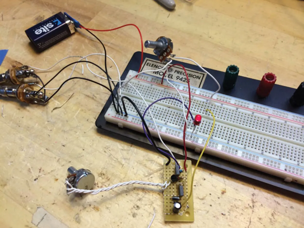
Photo 7 — You'll test your completed board on the breadboard before boxing it up.
Once you learn the technique, you'll be able to transpose most stompbox circuits directly from schematic to perf board—and almost every stompbox schematic is available online. (Yes, reading schematics is one of our topics.) After assembling the circuit board, you'll test it using the breadboard (Photo 7).
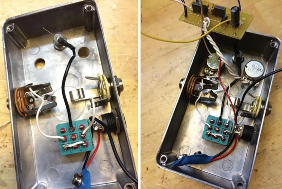
Photo 8 (left): Your stompbox will have pro hardware, including true-bypass switching, a DC adapter, and a power-indicator LED. Photo 9 (right): In the final assembly, your circuit board rests atop the gain and volume pots.
5. Boxing the circuit. Finally, you'll box everything up. You'll install the jacks, footswitch, LED, and DC adapter into the enclosure (Photo 8) and then add the circuitry (Photo 9).
Tools.
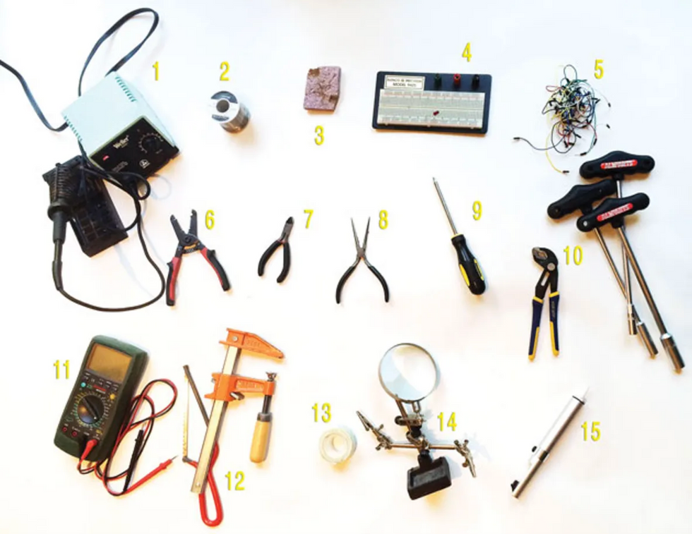
The tools you need—plus a few that are nice to have.
You'll need these tools to complete the project. Ones marked "optional" are nice to have too.
1. Soldering iron. (Preferably 30 watts or more, but not a large gun-type iron. A "soldering station" with a temperature control is a big plus. Use a fine, narrow soldering iron tip—the best choice for small-format electronic work.)
2. Lead-free solder. (Less toxic than the leaded kind, but still nasty.)
3. A damp sponge to clean the soldering iron's tip.
4. A small electronics breadboard. (They make large-format ones, but most stompbox circuits are simple enough for a small board.)
5. An assortment of jumper cables. (You can make your own, but the prefab ones have metal tips that don't fray from repeated use.)
6. Wire stripper.
7. Wire cutter. (Most strippers have cutters, but you'll probably want a separate flush-edged tool for tight, close cuts)
It's never too early to modify projects to better meet your musical needs and personal style. Even in this simple circuit, small modifications can dramatically alter the effect's sound and response
8. Needle-nosed pliers.
9. Phillips-head screwdriver.
10. An adjustable wrench or a wrench set. (Long-handled luthiers wrenches are nice if you can afford them—plus you can use them for guitar repairs.)
11. A digital multimeter. "Auto-ranging" meters are the easiest to work with. These have many functions, and the high-end ones can be quite complicated. But even budget models should have the functions needed for this project: a voltmeter, an ohmmeter, and a continuity function (a beeper that sounds when you touch the test terminals to any two points that are linked electronically).
12. A small saw and vise for cutting perf board to size.
13. Double-sided foam tape
14. Optional: a "helping hand" vise to hold components steady while soldering.
15. Optional: a syringe-style de-soldering pump.
… plus an electric guitar, an amp, and two audio cables.
Parts.
You can get some parts from any electronics supplier. Others you must order from a stompbox parts specialist.
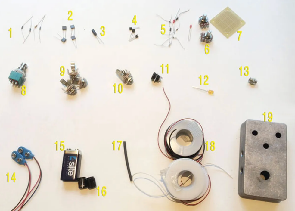
Here's your "bill of materials" (BOM)—the engineer's term for a parts list. Part of the project involves auditioning multiple components to choose your favorites, so not everything in the list will appear in the final pedal. The extra parts are quite inexpensive, so I recommend getting them all—you'll learn a lot. (In the U.S., a complete set of parts should cost around $50.)
1. Five ¼-watt metal film resistors. Values: 470R, 4.7K, 10K, 68K, 2.2M.
2. Four non-polarized capacitors (caps):
· 473 (also called .047µF or 47n)
· 683 (also called .068µF or 68n)
· two units of 104 (.1µF or 100n)
These can be polyester film, "box style," or ceramic—they all sound the same in this circuit. Get small-format caps rated between 50 and 100 volts, not the large-format caps used in amps and other AC-powered devices. (You'll only use two of these in the final pedal.)
3. One 16V 22µF electrolytic capacitor. (This cap type is polarized.)
4. Three transistors: 2N5088, 2N5089, and 2N3904. (You'll only use one in the final pedal.)
5. Eight diodes, two each of the following. (Not all will appear in the final pedal.)
- 1N4001
- 1N914
- 1N34A
- red 3 mm LED
6. Two 16 mm potentiometers ("pots"): A100K and C10K. (Substitute a B10K if you can't find a C10K.)
Schematics can look intimidating, but it doesn't take long to learn the basic symbols.7. A piece of perf board (perforated circuit board) at least 15 holes in width and seven in height. Chances are you'll saw a standard-sized 45 mm x 45 mm piece (shown) in half.
8. A 3PDT footswitch.
9. Three 1/4" mono jacks. (One is for the pedal, and two are for your breadboard testing rig.)
10. One 1/4" stereo jack.
11. One DC jack. (I used the standard type with an internal nut for the photos in this guide, though you may find it easier to work with an external-nut model.)
12. One 5 mm LED (any color).
13. One 5 mm LED bezel.
14. Two battery snaps. (One for the pedal, and one for the breadboard rig.)
15. One 9-volt battery.
16. Two knobs of your choice.
17. One 2" length of 1/8" heat-shrink tubing. (You can substitute standard electrical tape.)
18. Hookup wire, preferably 24-gauge, stranded and pre-bonded. (For visual clarity, it may help to use several contrasting colors, such as black, red, and white.)
19. One 1590B-size enclosure drilled for two knobs, footswitch, input, output, LED, and DC jack. You can order a pre-drilled box, or use a drill press to make your own holes. Use a larger enclosure if you like, though everything should fit into a compact 1590B. (If you have a drill press, you can save a couple of bucks by drilling your own holes. For an appropriate drill template, Google "1590B drilling template.")
Sourcing parts.
Stompbox parts tend to fall into two categories: those you can get from large electronics supply houses, and those sold chiefly by stompbox specialists. Large suppliers such as Mouser, Digi-Key, and Allied often have the lowest prices, but they don't stock some of the essentials. Meanwhile, the specialized stompbox vendors often carry both specialized and non-specialized parts, and the convenience of one-stop shopping may compensate for slightly higher prices on generic parts.
This isn't a complete list of stompbox parts specialists—just three reliable U.S.-based vendors with fine reputations, listed in alphabetical order. I've had great service from all three businesses.
Meanwhile, I hear good things about Germany's Banzai Music from my friends in the E.U.
Mammoth Electronics has created a preassembled kit with all the parts needed for this project. (Premier Guitar has no financial stake in the product—it's merely offered as a convenience.) The parts are good and the prices are competitive, but it's just one way to go. The kit includes all needed parts, but you must provide the tools. More details here.
Despite (or maybe because of) the circuit's simplicity, it offers terrific overdrive tones. It's a fine alternative to the Tube Screamer-influenced designs found in perhaps 90 percent of today's overdrive pedals.
Your workspace. Work somewhere with decent lighting and ventilation. Expect everything to take longer than planned, so don't start working at your kitchen table if you plan to eat there this week. Remember, a clean, well-organized workspace is a sign of a clean, well-organized mind. My bench is a filthy junk pile.
Safety first (and second and third). This project requires tools and techniques that can hurt you if you're not careful. Fortunately, it's pretty much impossible to electrocute yourself with 9-volt circuits like this one, but it's all too easy to cut or burn yourself.
When in doubt, step away from the bench and seek help. Don't touch things that are hot or sharp. Wear eye protection. Don't work when you're angry or stressed. Don't leave anything dangerous where kids or pets can find it. You know the drill—including the fact that you proceed at your own risk, and that neither I nor Premier Guitar can assume any responsibility for injury, property damage, or other unfortunate events that may occur while attempting this project. Be smart and careful, okay?
Common-sense soldering. If you've never soldered, it can be intimidating. And yes, it's possible to burn things, including yourself. But it's actually an easy procedure that quickly becomes second nature. If you've never soldered before, watch a few YouTube soldering tutorials. Start with this one, in which a clever 11-year-old covers most of what you need to know in three fast minutes.
Some basics.
- Don't touch the hot part.
- Don't leave a hot iron unattended.
- Work in a ventilated area. Even if you're using lead-free solder, it can't be healthy to inhale those fumes for hours!
- Wear eye protection.
- "Tin" the iron's tip by touching a bit of solder to it before starting.
- Keep a damp sponge or rag handy and swab the iron's tip frequently to keep it clean.
- Instead of touching solder to the iron's tip, try to heat the target component and melt the solder against the component. (But yeah, sometimes we cheat and quickly touch the solder to the iron for a fraction of a second to get it flowing.)
- A good solder joint is shiny, smooth, and shaped like a Hershey's Kiss. If it's dark, or sits on the surface like a water droplet, reapply the iron.
- If you make mistakes, it may help to have a syringe-type de-soldering tool. (You simply re-melt the solder, and then suck it up with the tool.)
- Consider using a "helping hands" vise to hold your components, leaving both your hands free for work.
It's possible to complete this project with a bare-bones pencil-type soldering iron, but it's far easier if you use a "soldering station" with adjustable temperature from a company such as Weller or Hakko. Simple hobbyist models start at around $40, and fancier models go for about double that. But don't use big, high-wattage soldering guns—they're too powerful for work like this. Use a fine, narrow soldering iron tip suitable for delicate electronics work.
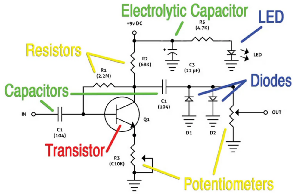
Photo 10 — You can make sense of many stompbox schematics if you learn half a dozen symbols.
Working with schematics. A schematic is simply a graphic representation of a circuit. Schematics can look intimidating, but it doesn't take long to learn the basic symbols. Photo 10 shows the schematic for this project. The build guide PDF discusses it in detail, but here's a quick intro:
- Schematics are usually arranged with the power connection at the top, ground connections at the bottom, input to the left, and output to the right.
- The zigzag lines depict resistors.
- The potentiometer symbol is like the resistor symbol, but with an added arrow to indicate the middle lug.
- Parallel lines symbolize non-polarized capacitors.
- The electrolytic cap symbol adds a curved line and a plus sign to indicate polarity.
- The diode symbol includes a triangle and a line. The side with the line is the negative terminal. The LED symbol adds arrows representing emitted light.
- Like most circuits, this one includes many connections to ground. We could connect them all with lines in the schematic, but the schematic is easier on the eye is we indicate ground connections with a simple symbol: the downward-facing triangle.
Don't sweat it if you're still confused—it's covered extensively in the build guide.
Stompbox parts tend to fall into two categories: those you can get from large electronics supply houses, and those sold chiefly by stompbox specialists.
Mods of the gods.
Sure, you might be a beginning builder, but chances are you have strong tastes when it comes to guitar sound. It's never too early to modify projects to better meet your musical needs and personal style. In fact, you'll be doing just that within the first few minutes. Even in this simple circuit, small modifications can dramatically alter the effect's sound and response.
Your modding experiments will focus on three areas:
- You'll try different values for the input capacitor (labeled C1 in Photo 10). This part acts as a high-pass filter, removing lows. But the result isn't quite like, say, turning down the bass knob on your amp, or using EQ to remove lows from a recording. Here at the front of the circuit, slight component variations alter the effect's fundamental character.
- You'll audition three different transistors (the part labeled Q1 in Photo 10). This component defines the circuit's gain. You can make this an understated overdrive or an angry chunk machine.
- You'll experiment with different combinations of clipping diodes (parts D1 and D2 in Photo 10). The result can range from soft, warm distortion to razor-edged sizzle.
DIY not? Remember, this project isn't just about building a cool distortion pedal. The goal is learning the "whys" as well as the "hows" so you can a) apply these techniques to any project, and b) alter circuits to taste. I hope you find the process fun and informative, and that when the smoke clears—hee hee—you have an inspiring musical tool. For best results, maintain your patience and sense of humor, and don't freak out when you hit the inevitable hurdles.
There's much more info in the PDF build guide, including additional resources and troubleshooting tips. Download it if you dare!
Click to download the entire build guide in an easy-to-use PDF.
[Updated 8/10/21]