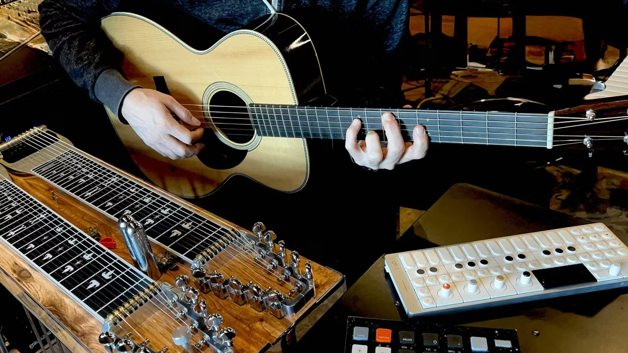
Sample your own performances, embrace mutations over replications, and let go of outcomes—here's how samplers and loopers can shock your music into strange new shapes.
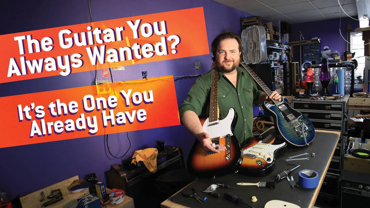
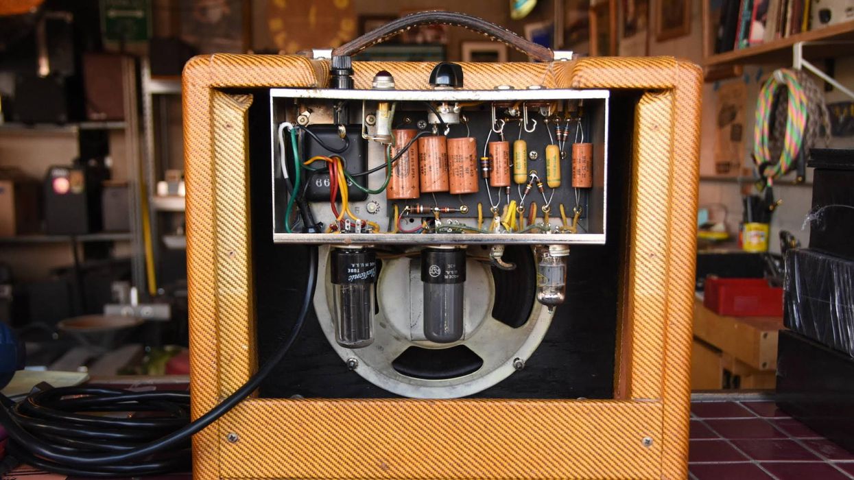
In the first installment of PG’s newest column, Colleen Fazio invites us into her shop to explore a 1959 Fender 5F1 Champ—complete with original components, a signed chassis, and 66 years of history.