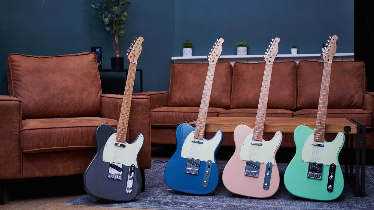
Photo courtesy Thomann Music/Harley Benton (https://harleybenton.com) Mod Garage Mod Garage: Prepping Your Electric’s Neck Dirk Wacker May 24, 2026
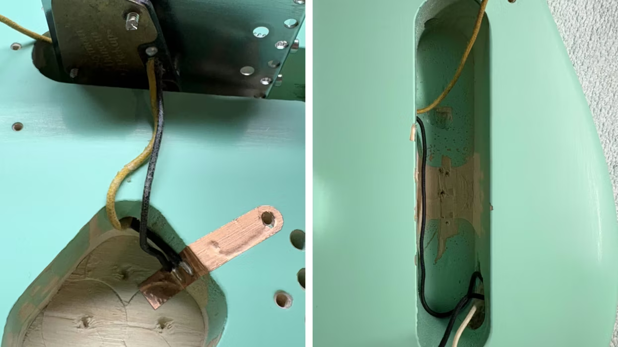
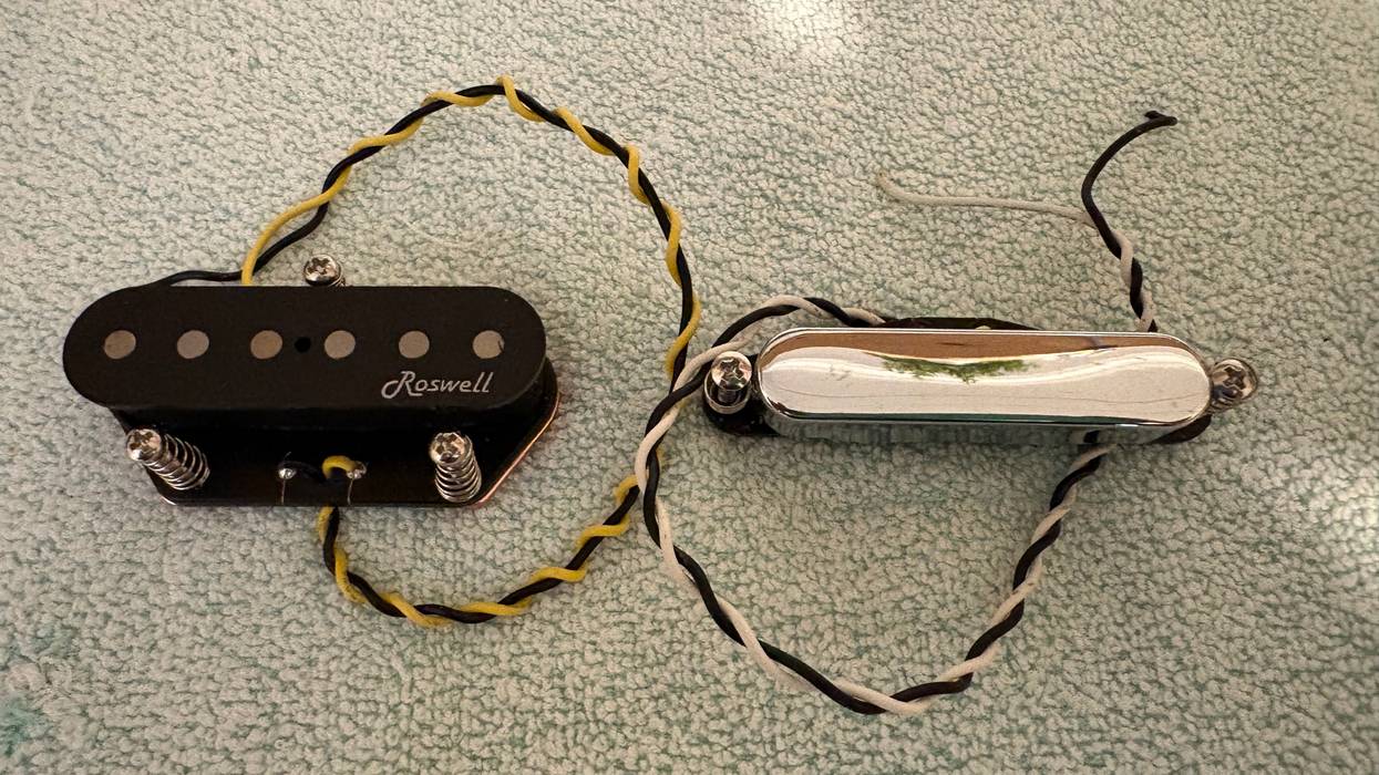
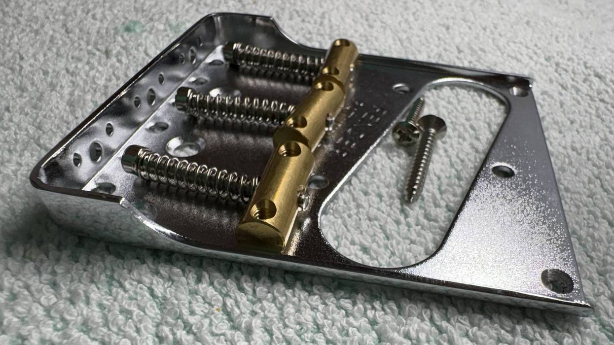
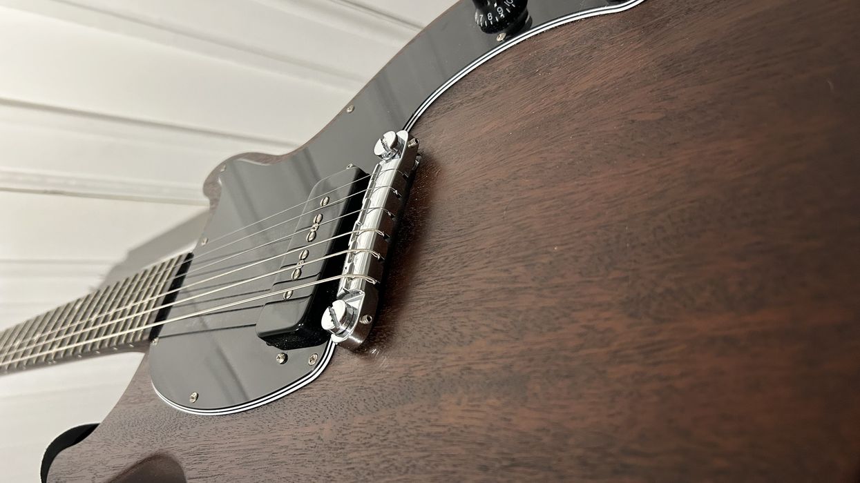
Mod Garage Tonewood Teardown: Pickups and Wiring for an Esquire-Style Electric Dirk Wacker Apr 13, 2026
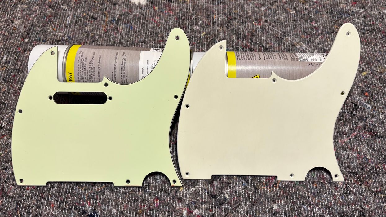
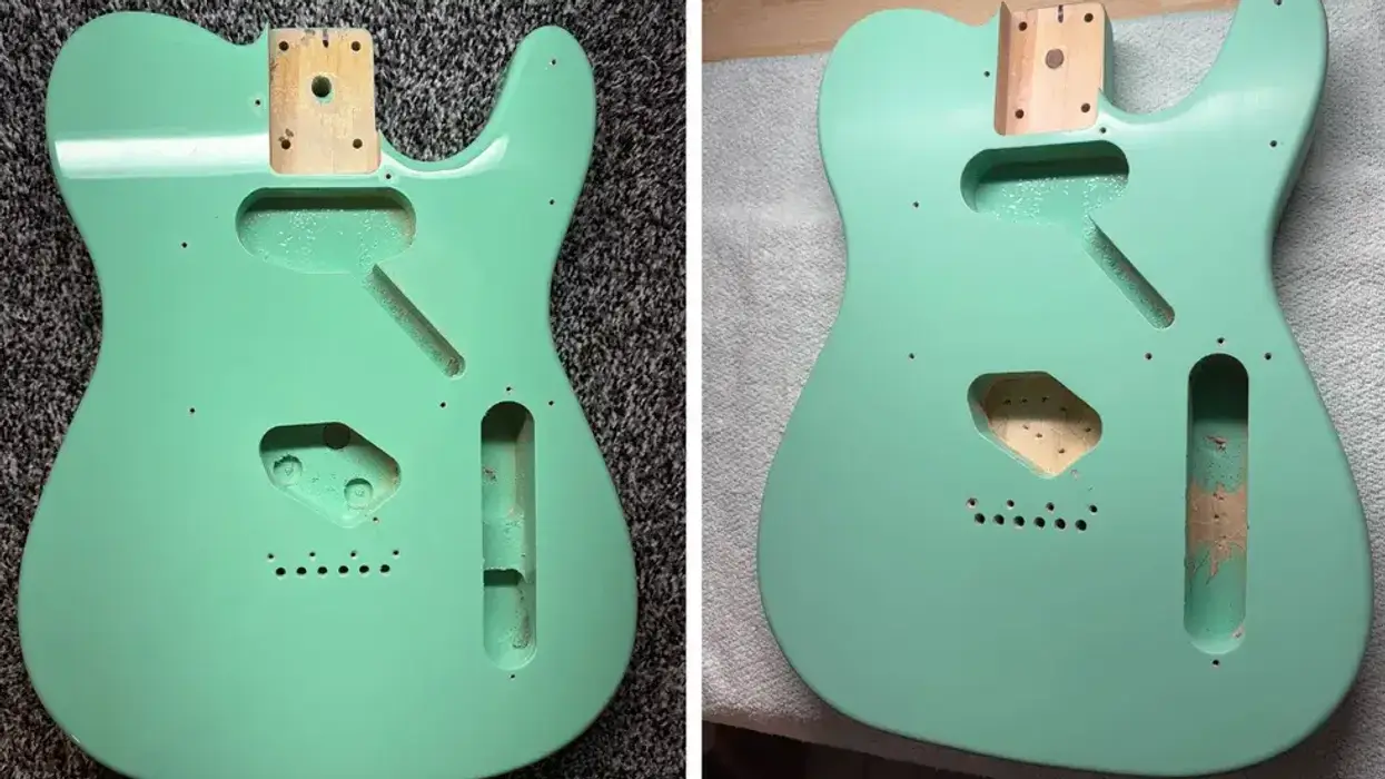
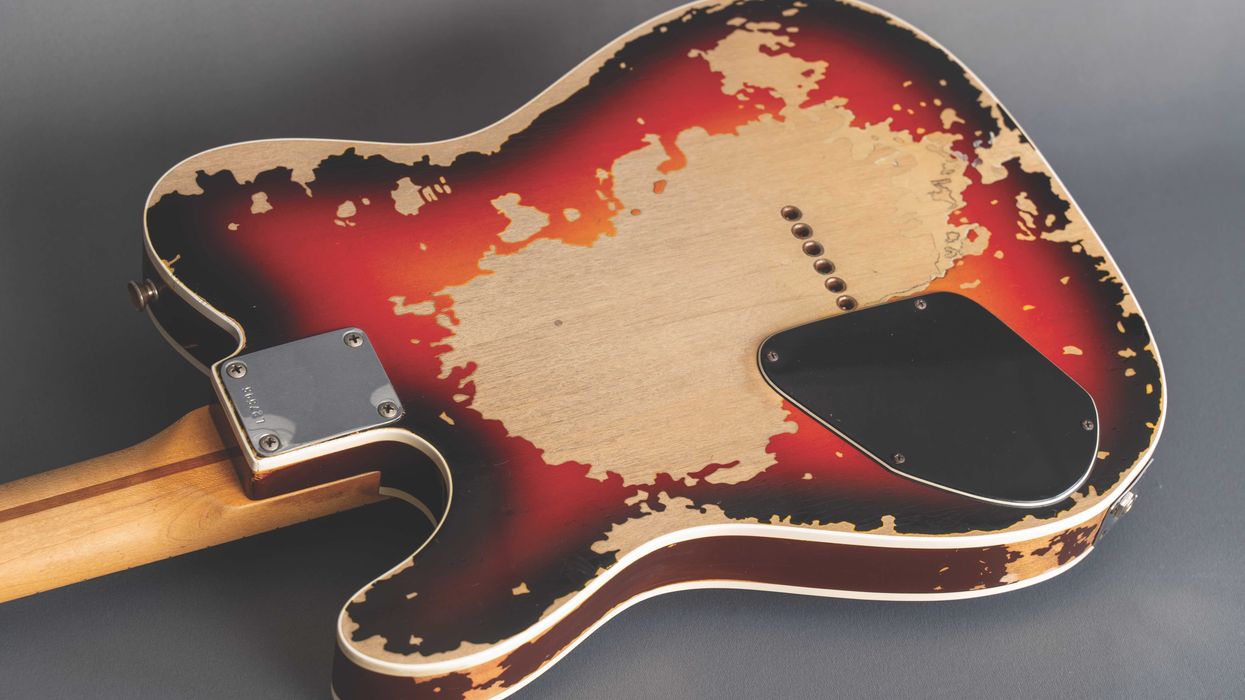
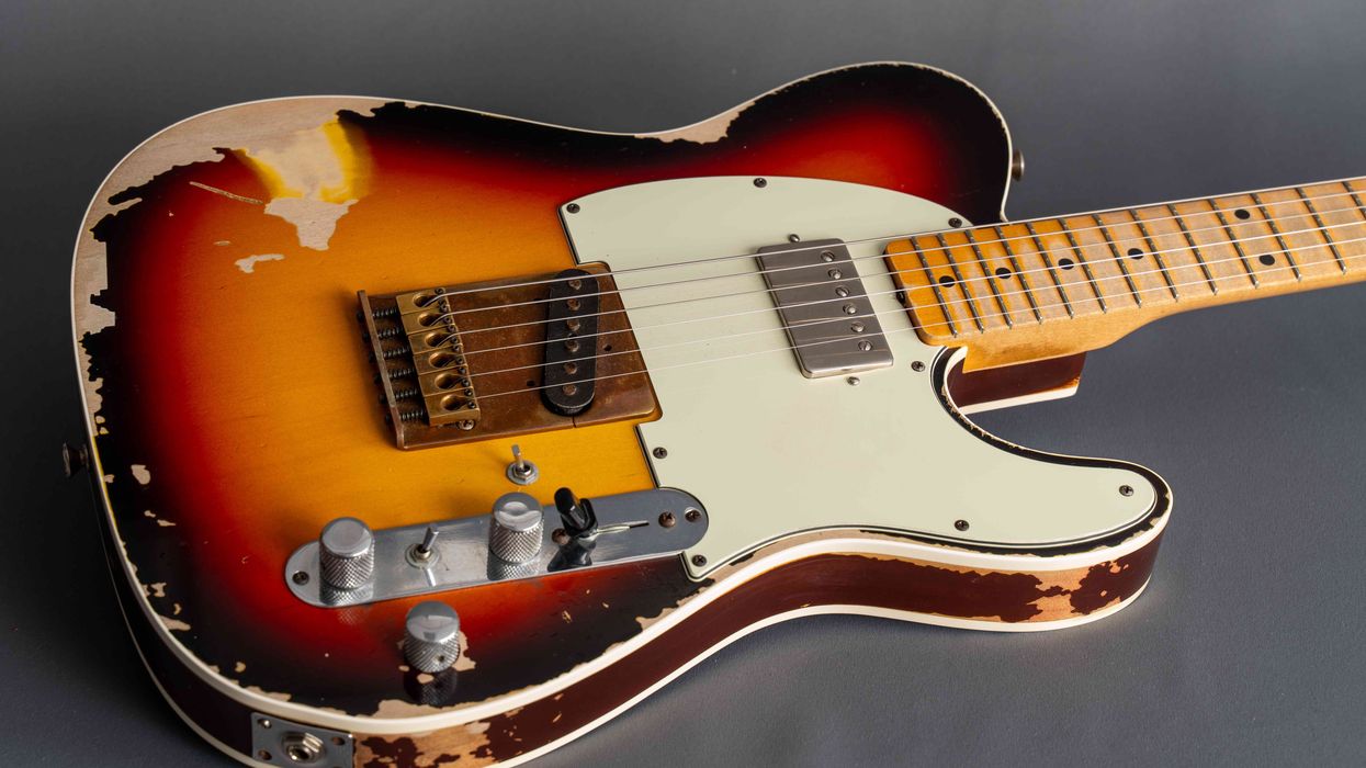
photo courtesy SINGLECOIL (https://singlecoil.com) Mod Garage Mod Garage Tonewood Teardown: Chasing the “Closet-Classic” Look Dirk Wacker Dec 24, 2025
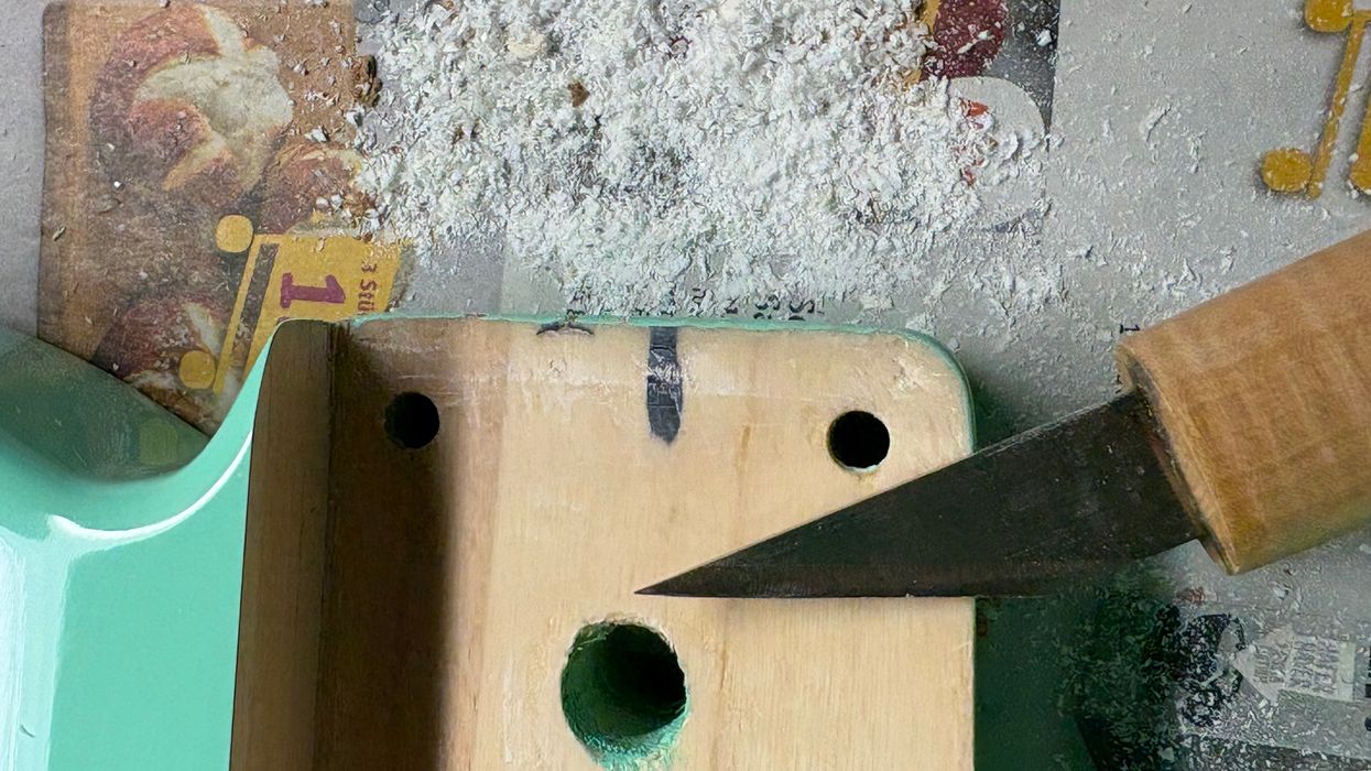
SINGLECOIL (https://singlecoil.com) Mod Garage Mod Garage Guitar Makeover: Neck-Pocket Cleanup and DIY Routing Dirk Wacker Oct 08, 2025
Photo courtesy Thomann Music/Harley Benton Mod Garage Tonewood Teardown: How Good Can a Cheap Guitar Sound? Dirk Wacker Aug 31, 2025
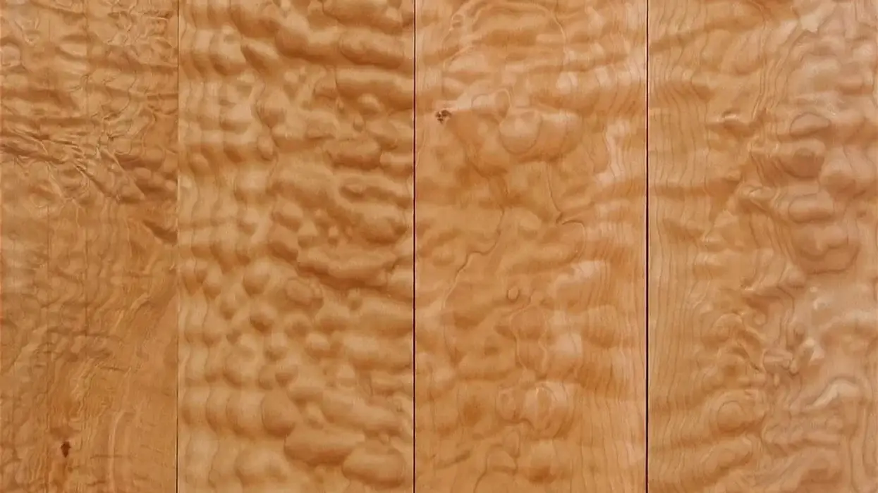
Mod Garage Feelings vs. Physics: What Matters Most for Electric Guitar Tone? If you want to know how your electric will sound through an amp, think about mass, not mojo. Dirk Wacker Aug 08, 2025
Mod Garage Electric Guitar Tonewood Teardown: Can We Get Good Sounds From Cheap Guitars? In the first part of a Mod Garage miniseries, our columnist sets some parameters on tone talk. Dirk Wacker Jul 24, 2025
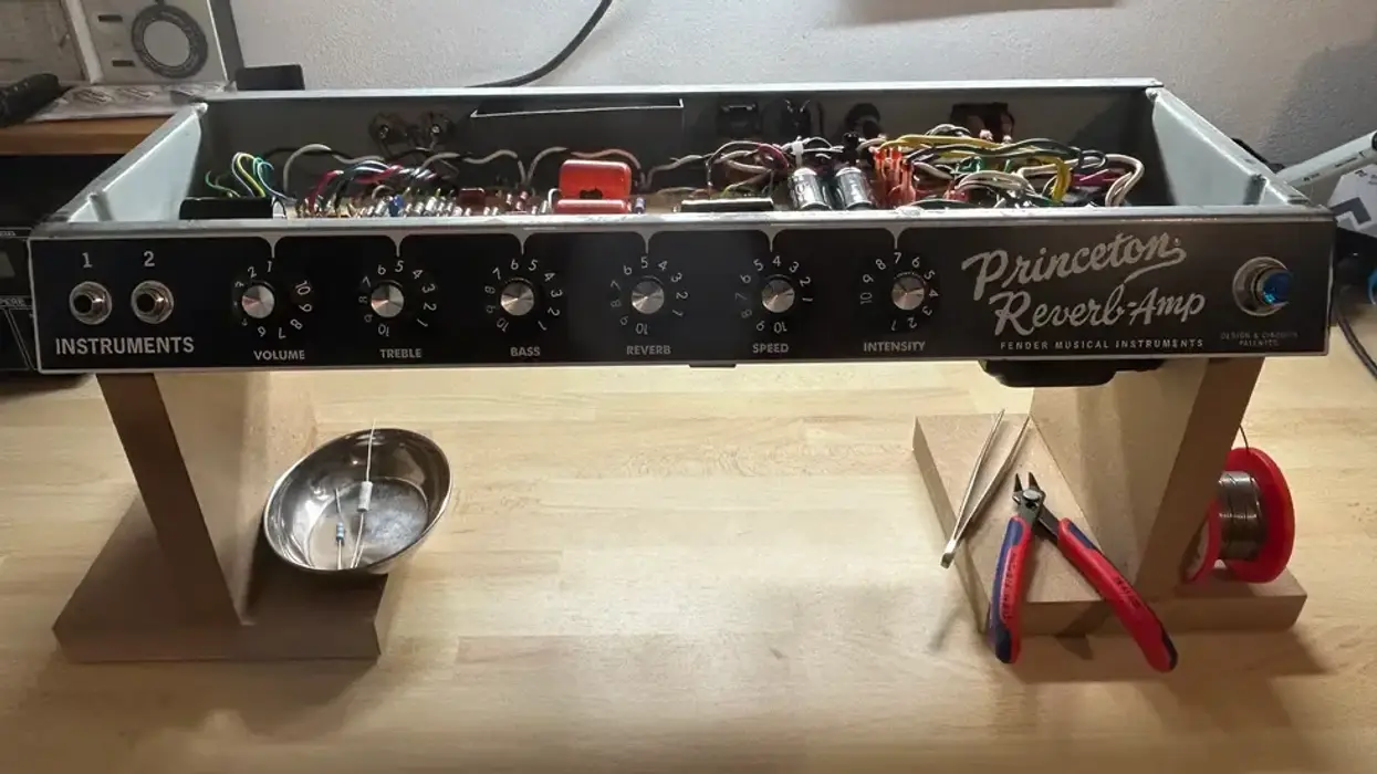
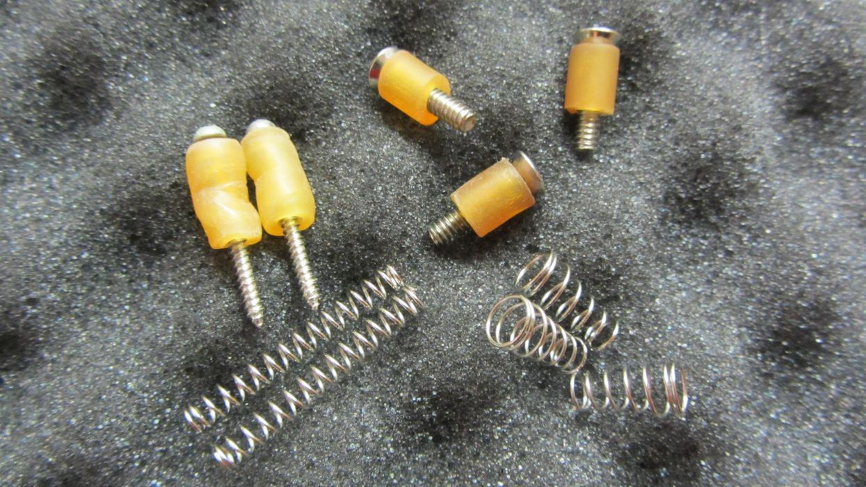
Mod Garage Reduce, Reuse, Recycle, Repair: Sustainable DIY Guitar Workshop Helpers You don’t need to blow your savings to set up a basic guitar workshop. Here are some quick-and-easy DIY tools you can rig up with household materials. Dirk Wacker May 27, 2025
Mod Garage Tipping Your Cap: Simple Mods for More Capacitance in Your Signal Chain Dirk Wacker Apr 26, 2025
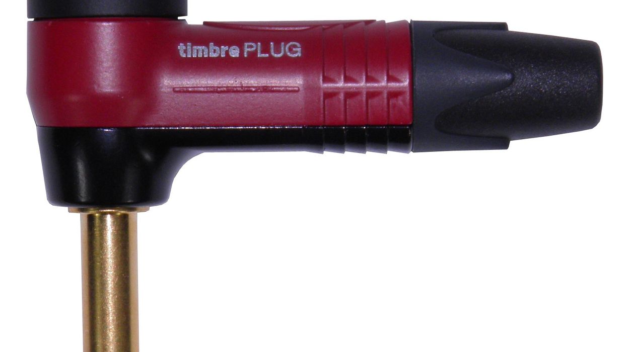
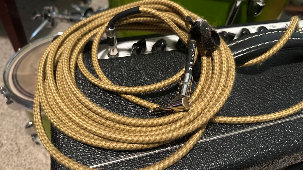
Mod Garage Are You Using the Right Guitar Cable? The least exciting piece of your rig can impact your tone in a big way. Here’s what you need to know. Dirk Wacker Mar 29, 2025
Mod Garage The Andy Summers Telecaster Wiring, Pt. 2 We’ve covered Andy’s iconic guitar and what makes it so special, so now we’ll get to building our own. Dirk Wacker Feb 26, 2025
Mod Garage Andy Summers Tele Wiring The Police guitarist’s go-to guitar is the source of a few mysteries, so let’s crack the code. Dirk Wacker Jan 27, 2025
Mod Garage Fighting Feedback on a Telecaster If you’re used to cranking your Tele, you may have encountered a feedback issue or two. Here are some easy solutions. Dirk Wacker Jan 11, 2025
Mod Garage The Dan Torres Mid Boost and Scoop Mod This simple passive mod will boost your guitar’s sweet-spot tones. Dirk Wacker Dec 13, 2024
Mod Garage Rory Gallagher’s Strat and Why He Used Fender Beveled Pickups How the Irish guitar virtuoso got a unique tone with a factory-stock Strat. Dirk Wacker Nov 23, 2024