| Other Installments: Part I Part III |
Part II: Standard Installation
Hello, and welcome back to “Mod Garage." After the basics from last month, we'll continue with some more details about the Stratocaster 5-way pickup selector switch. From countless emails I know one of the main problems when using a new switch is how to install it on the pickguard! This may sound funny, but it's true. You can rotate the switch 180 degrees and it will still fit the pickguard—so which is the correct orientation of the switch?
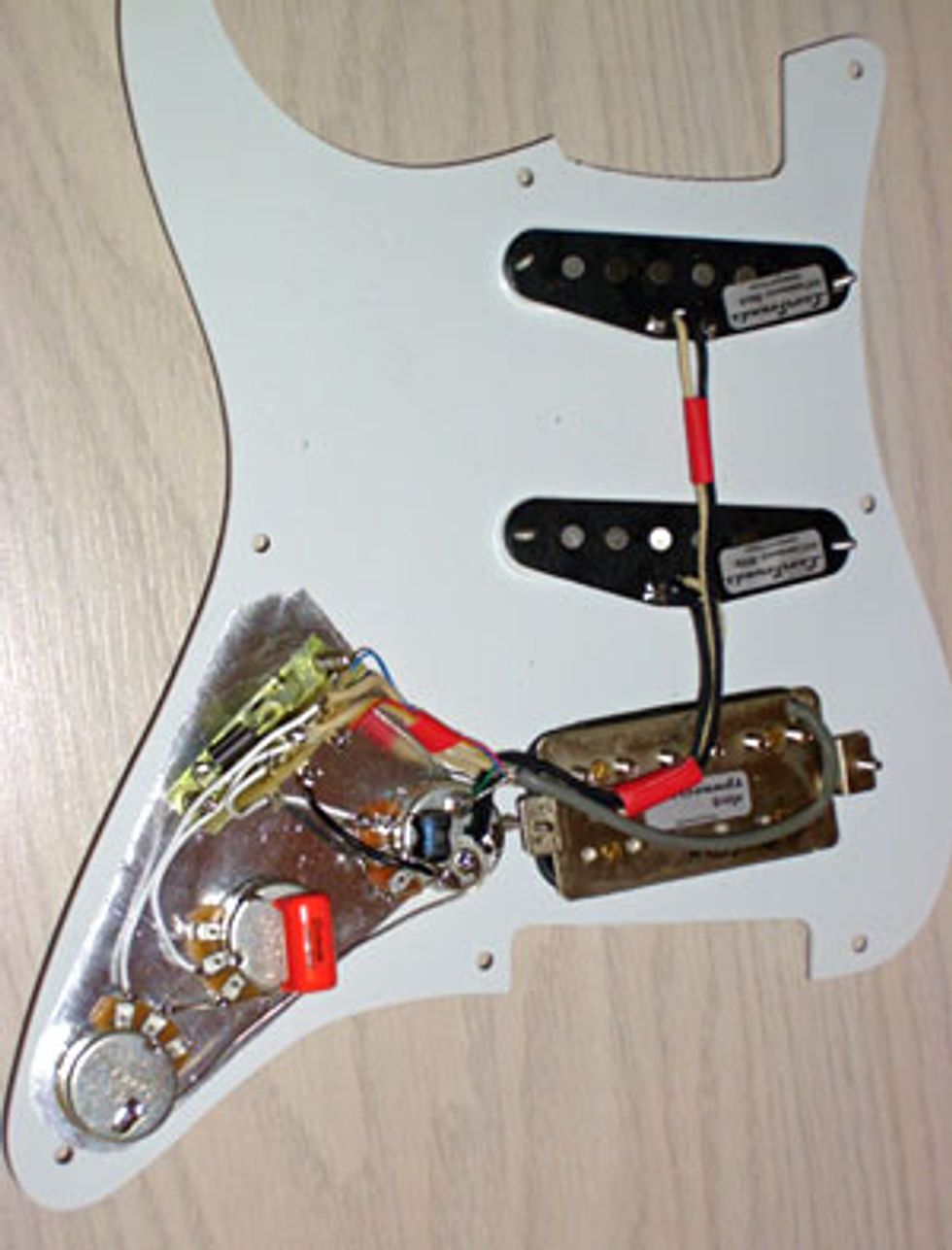 From an electrical point of view, it doesn't make any difference, because the switches are mirrored and will work in both configurations. All you have to do is to take care of how you wire it up, and that's it. In real life, the standard is to mount the open switches with the switch spring facing the edge of the pickguard, as shown in the pic to the right. There are also open switches without this spring, in which case the metal-framed side of the switch (showing the screws) is the one that should face the edge of the pickguard. Closed switches should be mounted with the soldering lugs facing the pots, so all connections are coming from this direction.
Now it's time to talk about the terminology, so we're all on the same page when talking about the individual lugs of the switch. In general, our switch has two rows, or “stages," with four soldering lugs each. Below, you can see the schematic of our standard open CRL switch with added terminology.
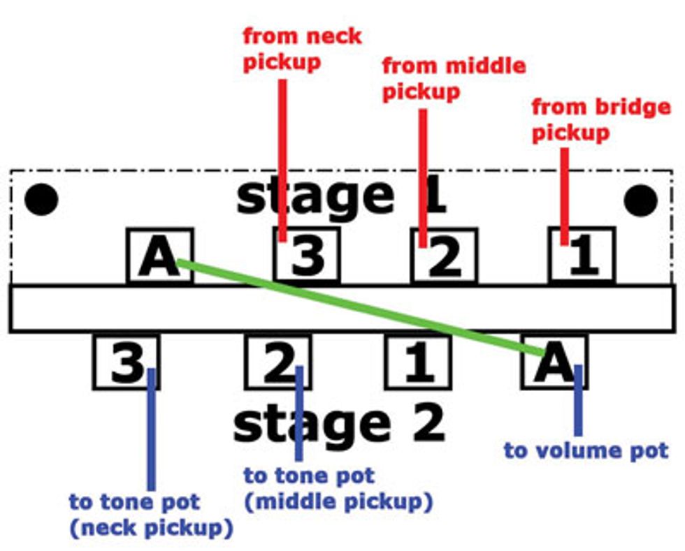
Stage 1 is also called the “input stage," while stage 2 is the “output stage." Each stage of the switch has three inputs (lugs 1, 2 and 3) and one output (lug A). In a nutshell, you should have hot wires from the pickups going into the switch at stage 1 (lugs 1, 2 and 3) and a hot wire that goes out of the switch at stage 2 (lug A) to the volume pot. From there, the signal goes to the tone pots and the output jack. Please have a look at the diagram below, showing you the standard Stratocaster wiring.
Notice the green connection (jumper wire) that connects both stages. This allows each pickup signal to exit out of the same lug, and connect to the volume pot. In theory, lug 1 of stage 2 would connect to the tone pot of the bridge pickup, but as you know, a standard Stratocaster offers no tone control for the bridge pickup. As you have seen, though, in one of our previous mods, you can connect this lug to lug 2 of stage 2, to route the tone control for the bridge pickup to the tone pot for the middle pickup, so you can control both pickups with one tone pot. I think you've got the idea, right?
As I said, it's not as hard as you might have expected, and I'm sure you've got the basics now. If you want to go deeper, I highly recommend you get yourself an open CRL switch and a DMM with an audible continuity testing function. You can connect one testing wire from the DMM to any lug of stage 1, flip the switch and see on stage 2 what happens there. This is a very fascinating procedure, and you can learn a lot from it.
Next month we'll talk about how to transfer this knowledge to any other 5-way switch before we start to do more mods. So stay tuned and keep on modding!
Dirk Wacker
Dirk Wacker lives in Germany and has been addicted to all kinds of
guitars since the age of five. He is fascinated by anything that has
something to do with old Fender guitars and amps. He hates short scales
and Telecaster neck pickups, but loves twang. In his spare time he
plays country, rockabilly, surf and Nashville styles in two bands,
works as a studio musician for a local studio and writes for several
guitar mags. He is also a confessing hardcore DIY guy for guitars, amps
and stompboxes and runs an extensive webpage singlecoil.com about these things.