 Boss and Ibanez pedals universally use JFETs for bypass switching, and the operation of the circuit is a little mysterious until you have dug all the way to the bottom. Let’s look.
 Here’s a general overview: signal from the input jack goes first to a buffer, the first “triangle” on the left side of the circuit. This buffer makes the signal strong enough to drive the rest of the circuit without treble loss (tone sucking). The buffered signal drives both switch Sw1 and Sw3. Sw1 lets the signal into the effect circuit (in the rectangle in the middle of the picture) when it’s connected and Sw3 lets the signal go to the output buffer when it is connected. The switches are controlled by control signals “Effect” and “Bypass”, which are simply on/off voltages, not actual guitar signals. When the “Effect” signal is on, “Bypass” is off and vice versa, so that either Sw1 or Sw3 is connected and passing signal, but never both at the same time.
 “Effect” also connects Sw2 and signal that has passed through the effect circuit goes to the output buffer. When “Bypass” is on, Sw1 and Sw2 are disconnected, but Sw3 detours the signal directly to the output buffer.
 All three switches are really JFETs – Junction Field Effect Transistors. If you leave the Gate (G) of a JFET open, the Drain (D) and Source (S) will pass signal through, as the switch is connected. If you pull the Gate to a voltage less than the Source, the JFET will no longer pass audio signal. Source and Drain terminals are held at about half the battery voltage, so a higher voltage on the “Switch Control Signal” causes the Gate to be opened by the diode (switch “On”). The JFET then conducts audio signal. The diode, 1M resistor and capacitor slow down any sudden changes to the gate voltage to avoid pops and clicks.
“Effect” and “Bypass” signals are generated by a flip-flop, a circuit that has only two stable states. In the illustration, Q1 and Q2 and the parts around them are mirror images. Q1 can turn off Q2, and Q2 can turn off Q1. When you first connect 9V to the pedal, one of the transistors will come on a little faster than the other. The one to come on first will turn the other off.
 The footswitch circuit sends a little blip of an “off” signal to both transistors. Let’s say Q1 is off and Q2 is on. The footswitch sends an “off” signal to both. Q1 being off already ignores this, but Q2 will then turn off. The moment Q2 turns off, Q1 has to come on. When one side of the circuit “flips”, the other “flops”. The Boss and Ibanez pedals use both transistor collectors as switch control signals. I’ve marked the two collectors “Effect” and “Bypass”. When Q2’s collector is high, it turns on JFETs Sw1 and Sw2, and we hear the effect. When the Q1’s collector is high, it turns on JFET Sw3 and the dry signal comes out the output jack. When Q1’s collector is low, the effect is engaged and Q1 allows voltage passing through the “effect on” LED to go to ground, lighting up the LED.
 Even though the part values may not be exactly the same, you can now identify the bypass circuitry in Boss and Ibanez pedals and know how it all works.
R.G. Keen
Cheif Engineer
Visual Sound
www.visualsound.net


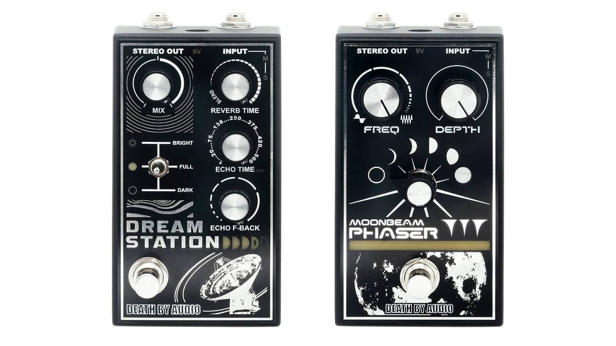
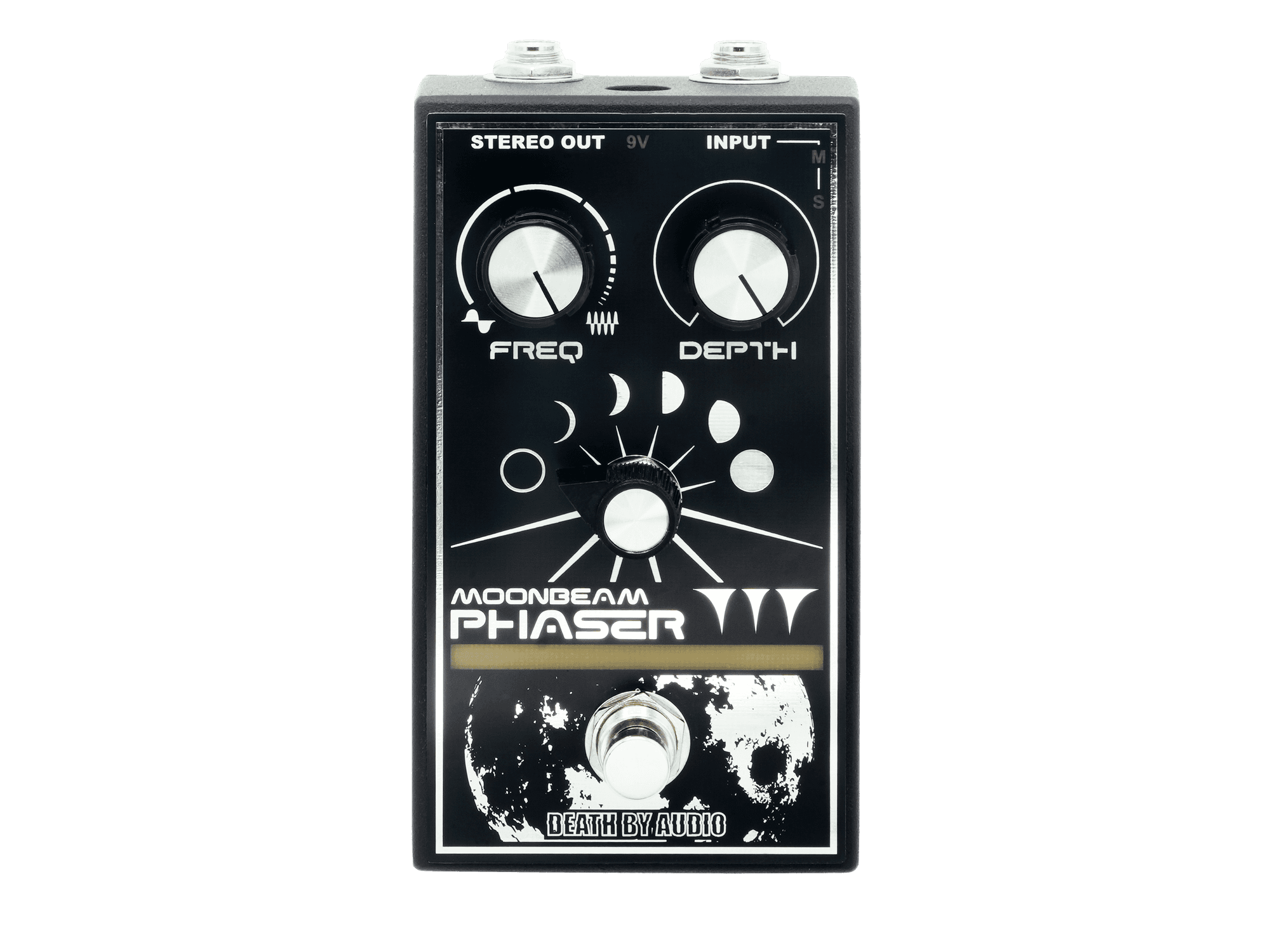
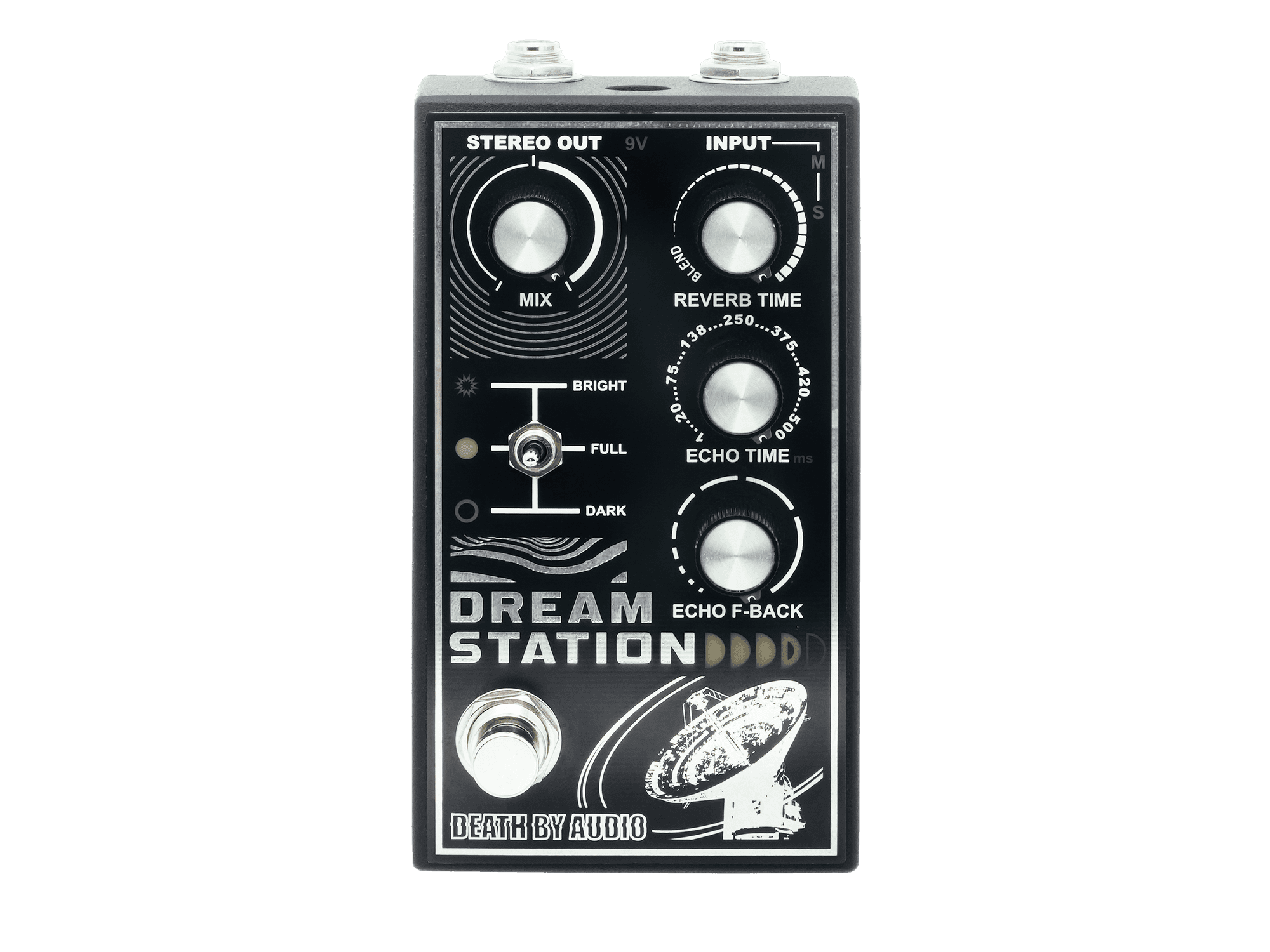 Death By Audio Dream Station and Moonbeam Review
 Death By Audio Dream Station and Moonbeam Review