This unique, low-wattage combo produces a potent mélange of Vox and Fender sounds—and sings with a loud and outsized voice. The PG Balthazar Cabaret 13 review.
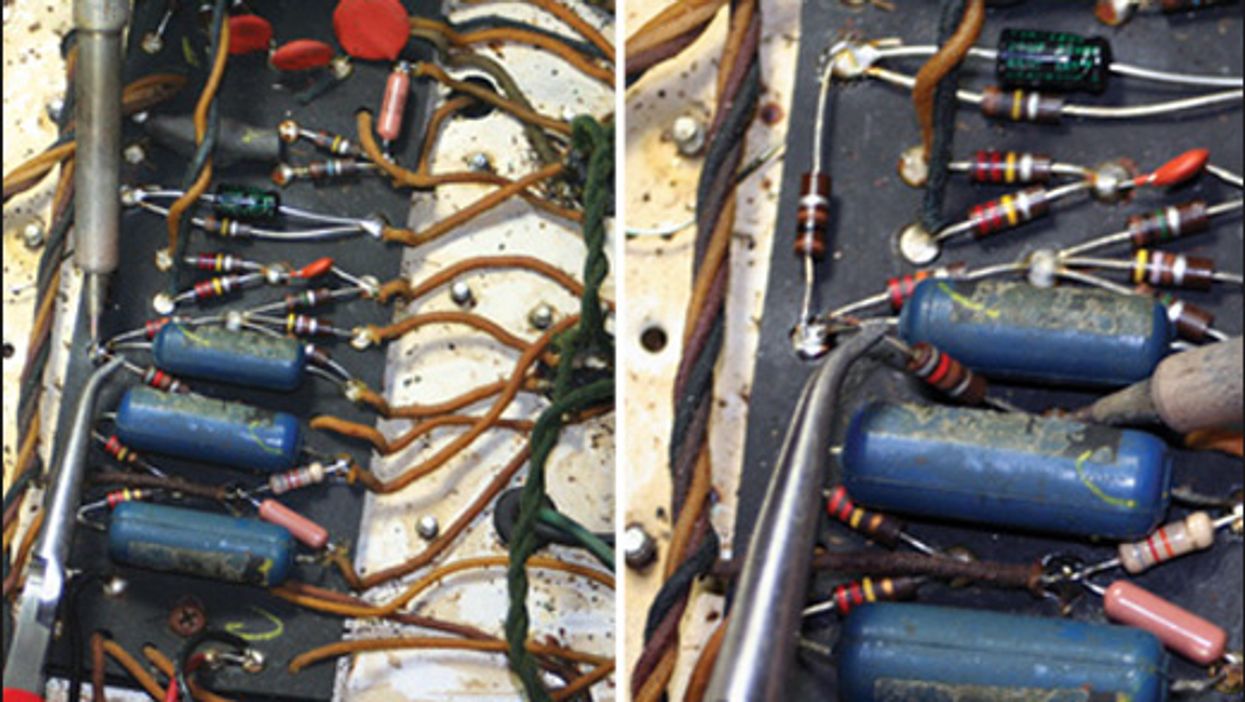
Removing or replacing a single component in your amp can have significant impacts on both its tonal character and the amount of gain or headroom on tap. Here we guide you through several easy projects you can do in relatively little time with a few basic tools.