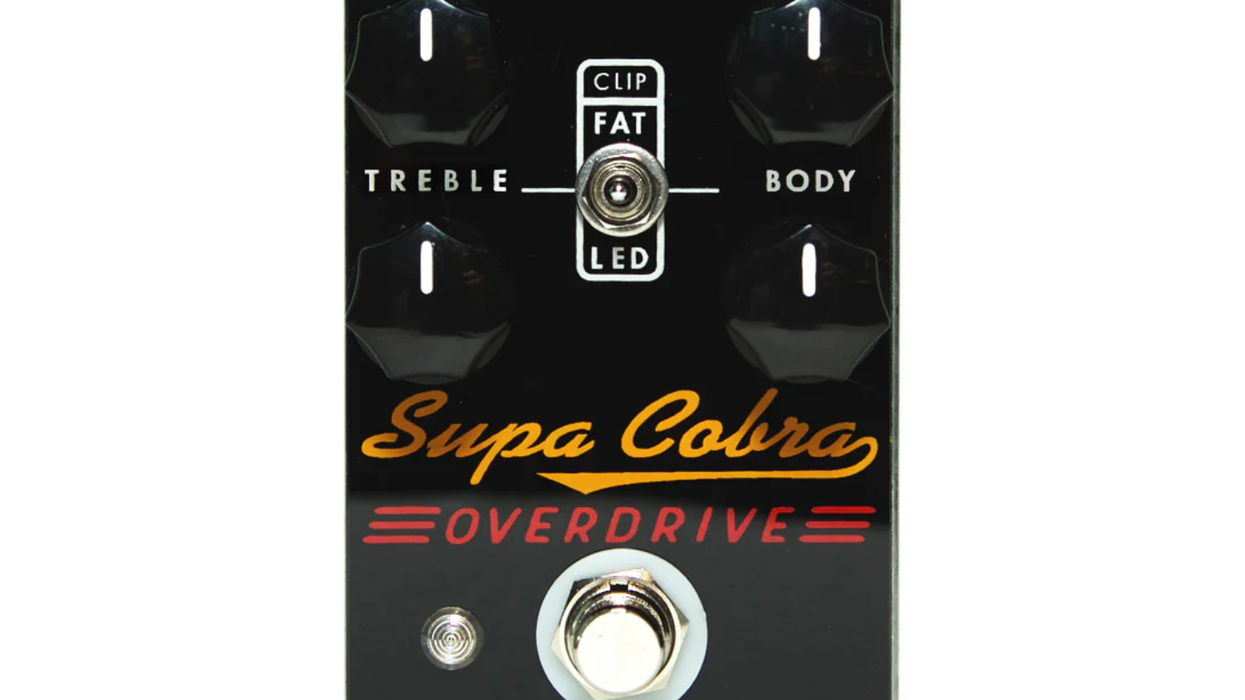
Reviews Olinthus Cicada Review The tiniest TS on Earth has loads of practical upside and sounds that keep pace with esteemed overdrive company. Charles Saufley Nov 15, 2024
Podcast Tyler Bryant on How to Leave Home and Start a Rock Band Rhett Shull Zach Broyles Sep 30, 2024
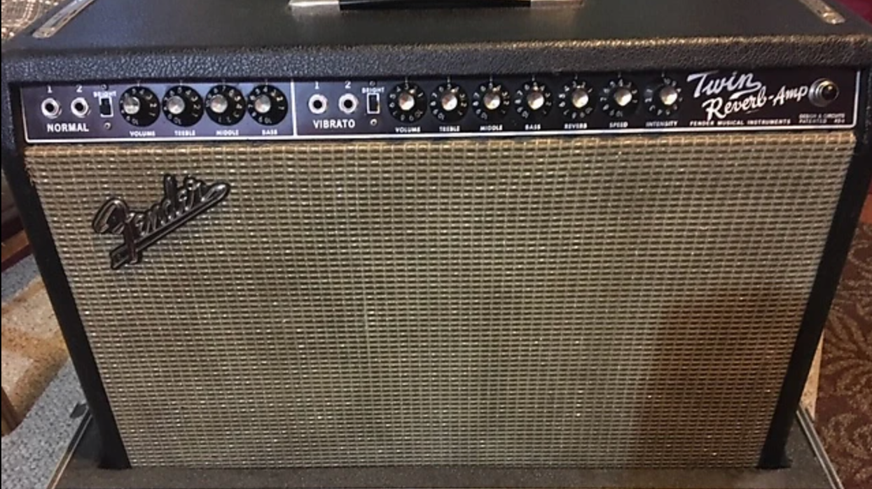
The Good Stuff A $400 Transition-Era Twin Reverb This amp with tone and headroom to spare proves that sometimes the best gear isn’t the most expensive or admired. Ted Drozdowski Aug 05, 2024
Artist Features Close-up on Marcus King's Gibsons & Pedalboard The roots guitar hero stopped at Nashville’s Guitar Center last week to show ’n’ tell his favorite Gibson guitars—and more. Premier Guitar Staff Jul 30, 2024
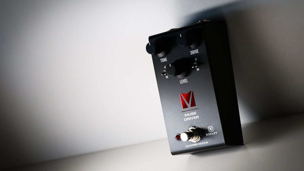
Sponsored Keeley’s Muse Driver: An Overdrive Workstation for the Masses Sponsored Content Feb 12, 2024


![Rig Rundown: Jared James Nichols [2023]](https://www.premierguitar.com/media-library/image.jpg?id=33032210&width=1245&height=700&quality=70&coordinates=0%2C0%2C0%2C0)