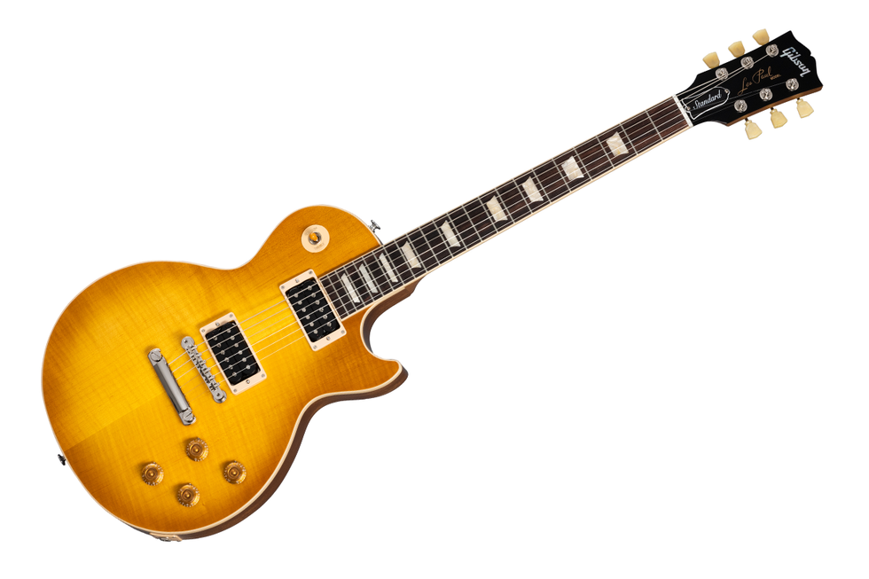
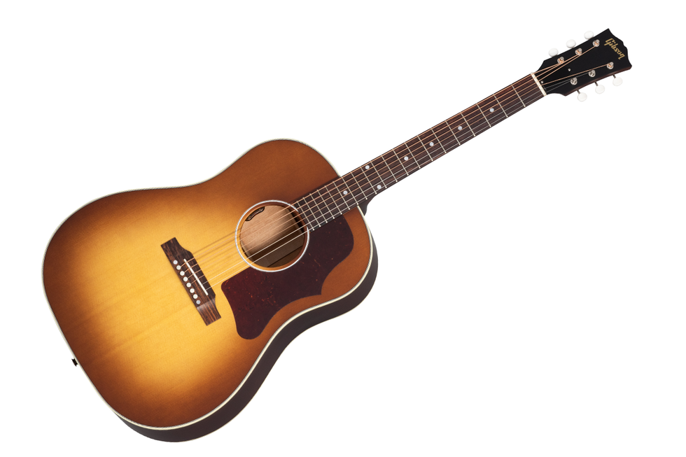
<p>The new <a href="https://www.premierguitar.com/tag/gibson?utm_source=website&utm_medium=link&utm_campaign=Smartlinks">Gibson</a> Les Paul™ Standard 50s Faded returns to the classic design that made it relevant, played, and loved -- shaping sound across generations and genres of music. It pays tribute to Gibson's Golden Era of innovation and brings authenticity back to life. The <a href="https://www.premierguitar.com/tag/les-paul?utm_source=website&utm_medium=link&utm_campaign=Smartlinks">Les Paul</a> Standard 50s features a satin nitrocellulose lacquer finish that gives it the look and feel of a long-treasured musical companion. It has a solid mahogany body with an AA figured maple top and a rounded 50s-style mahogany neck with a rosewood fingerboard and trapezoid inlays. It's equipped with an ABR-1 Tune-O-Matic bridge, an aluminum Stop Bar tailpiece, Vintage Deluxe tuners with Keystone buttons, and gold Top Hat knobs with dial pointers. The open-coil Burstbucker™ 1 (neck) and Burstbucker 2 (bridge) pickups are hand-wired to audio taper potentiometers and Orange Drop® capacitors.</p>
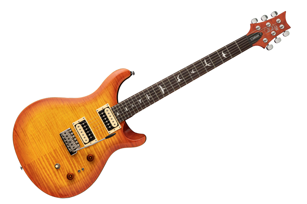
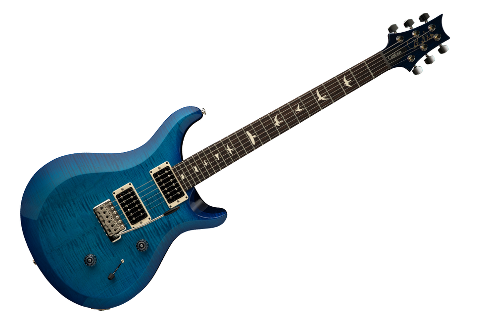
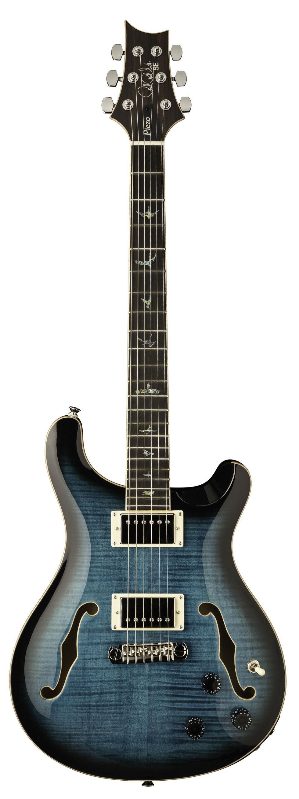
<p>The <a href="https://www.premierguitar.com/tag/prs?utm_source=website&utm_medium=link&utm_campaign=Smartlinks">PRS</a> SE Standard 24-08 is a mahogany-body workhorse guitar with powerful humbucking and true single-coil tones in one instrument. Its PRS TCI “S” pickups are paired with a 3-way toggle switch and two mini-toggle coil split switches that individually split the humbuckers into true single coils for a total of eight pickup configurations. Players can enjoy two full octaves thanks to the 24-fret, 25” scale length rosewood fretboard and wide thin maple neck, and the PRS patented, molded tremolo gives players added flexibility and control over their playing. With sonic range and rock-solid reliability, the PRS SE Standard 24-08 will keep you playing without compromise.</p>
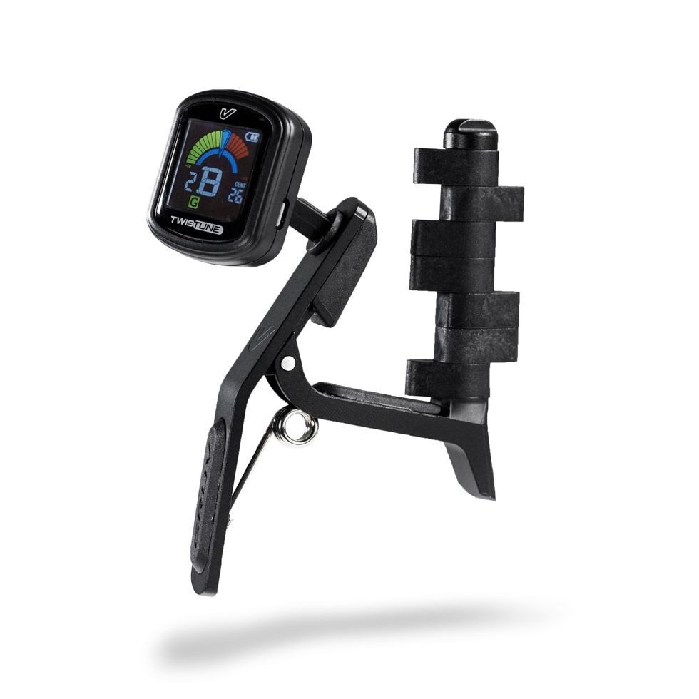
<p>Explore new guitar voicings and open tunings with the new Kaepo™, Gruv Gear's creative tuning guitar capo! Removable fretting pads can be set to any combination for nearly unlimited possibilities. Move the Kaepo quickly up and down the fretboard like a regular capo, without any tedious clamping or setup. Adjust the 7 individual fretting pads without any tools. Kaepo is also compatible with Gruv Gear's new Twistune™ rechargeable color tuner, for quick and convenient tuning on-the-fly. Works with most 6- and 7-string acoustic and electric guitars.<br/><br/>The Gruv Gear Kaepo is available on its own or bundled with the new Twistune tuner. Combine two or more Kaepos to open up even more tuning creativity!</p>
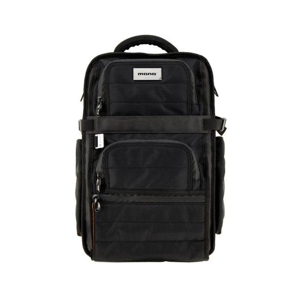
<p>The FlyBy Ultra comes packed with sleek upgrades while keeping the break-away laptop bag design of the original FlyBy. New features include an ultra-tough 1680D Ballistic Nylon exterior, reflective trim for visibility, waterproof zipper tape and new, larger compartments. The FlyBy Ultra also brings ergonomics to the next level with a luggage pass-through, and upgraded straps.<br/><br/>This is the tour pack that DJs and digital creators around the world carry and swear by. Get ready for the ultimate creator experience.</p>
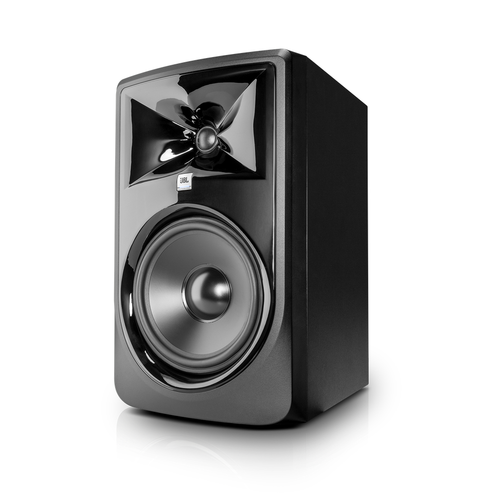
<p>JBL 3 Series MKII powered studio monitors make JBL performance available to every studio. The JBL Image Control Waveguide and refined transducers offer stunning detail, precise imaging, a wide sweet-spot and dynamic range that enhances the capabilities of any workspace. Featuring patented technologies derived from the JBL 7 Series and M2 Master Reference Monitors and, sporting a sleek, modern design, JBL 3 Series delivers outstanding performance and an enjoyable mix experience at an accessible price. Special sale pricing begins Thanksgiving day with the 305PMKII at $109 EA, 306PMKII at $149 EA, 308PMKII at $199 EA, and the LSR310S subwoofer at $299.</p>
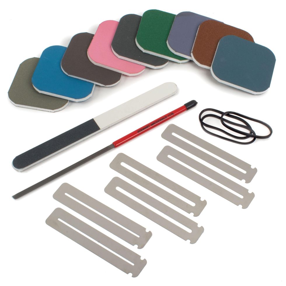
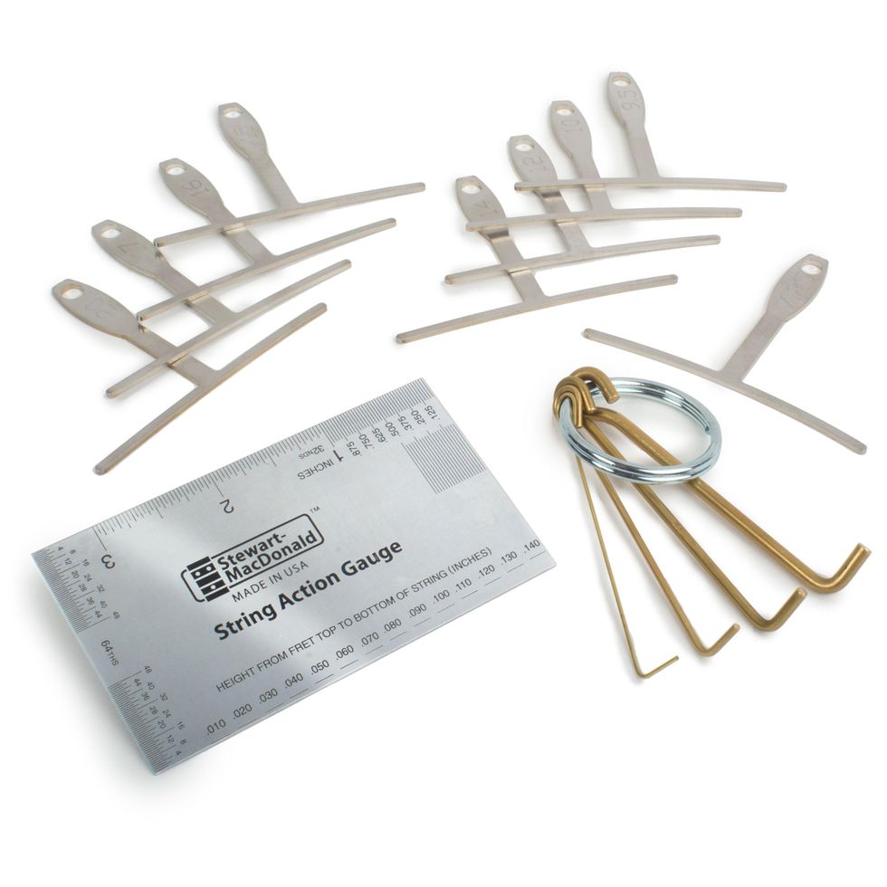
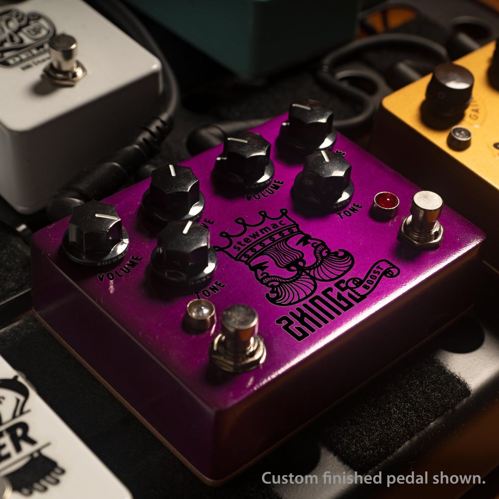
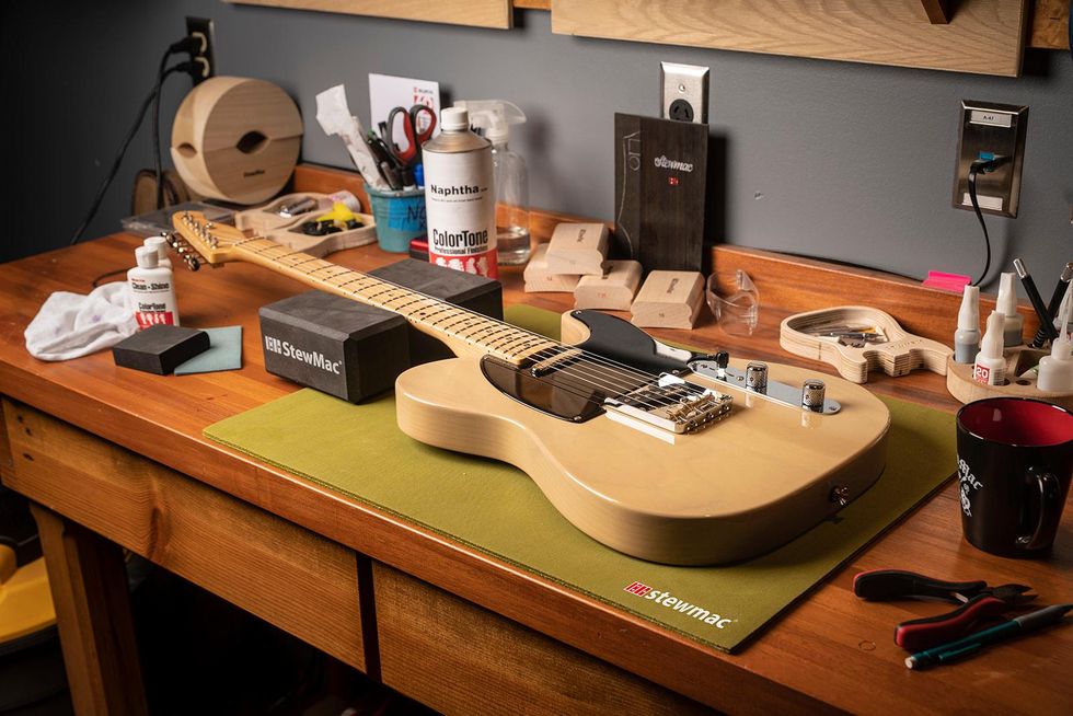
<p>Oh no! Stripped a tiny screw on your favorite guitar? Or even worse, scratched your guitar when the wrong screwdriver slipped? Never have that awful feeling again. <a href="https://stewmac.com" target="_blank">StewMac</a> has put together the ULTIMATE screwdriver set for every guitar owner. They tracked down all of those tiny specialty and hard to find bits—and we added a few of their favorite problem solvers. The StewMac Guitar Tech Screwdriver Set replaces a whole drawer full of bulky tools with exactly what you need. The set includes 36 essential bits for guitars, basses, and more, plus an easy-grip handle and extender. The included compact hard case is spill-proof and easily fits in your toolbox or guitar case (it’s a must-have for gigs). You won't find this at any hardware store—it’s only at StewMac.</p>
<p>Xvive’s U2, U3 and U4 wireless systems make going wireless easy, reliable and affordable, all with high-fidelity 24-bit/48kHz sound! They all recharge with any 5V USB power source, broadcast over a range of up to 90 feet, and have an imperceptible 5 ms of latency.<br/>U2 Guitar Wireless System is the go-to plug-and-play solution for guitarists and bassists, giving you five hours of trouble-free wireless freedom on a single charge.<br/>The U3 Microphone Wireless System turns any dynamic microphone into a wireless mic, in seconds. It can also be used to replace an XLR cable in other applications—for example between a mixer and a powered speaker cabinet!<br/>The U4 In-Ear Monitor Wireless System gives you a beltpack receiver for your in-ears or earphones and a transmitter to connect to the mixer; up to six musicians can use the system at a time, even with separate monitor mixes.<br/>For more info on these and other Xvive products, visit www.xvive.com and Play Free!</p>
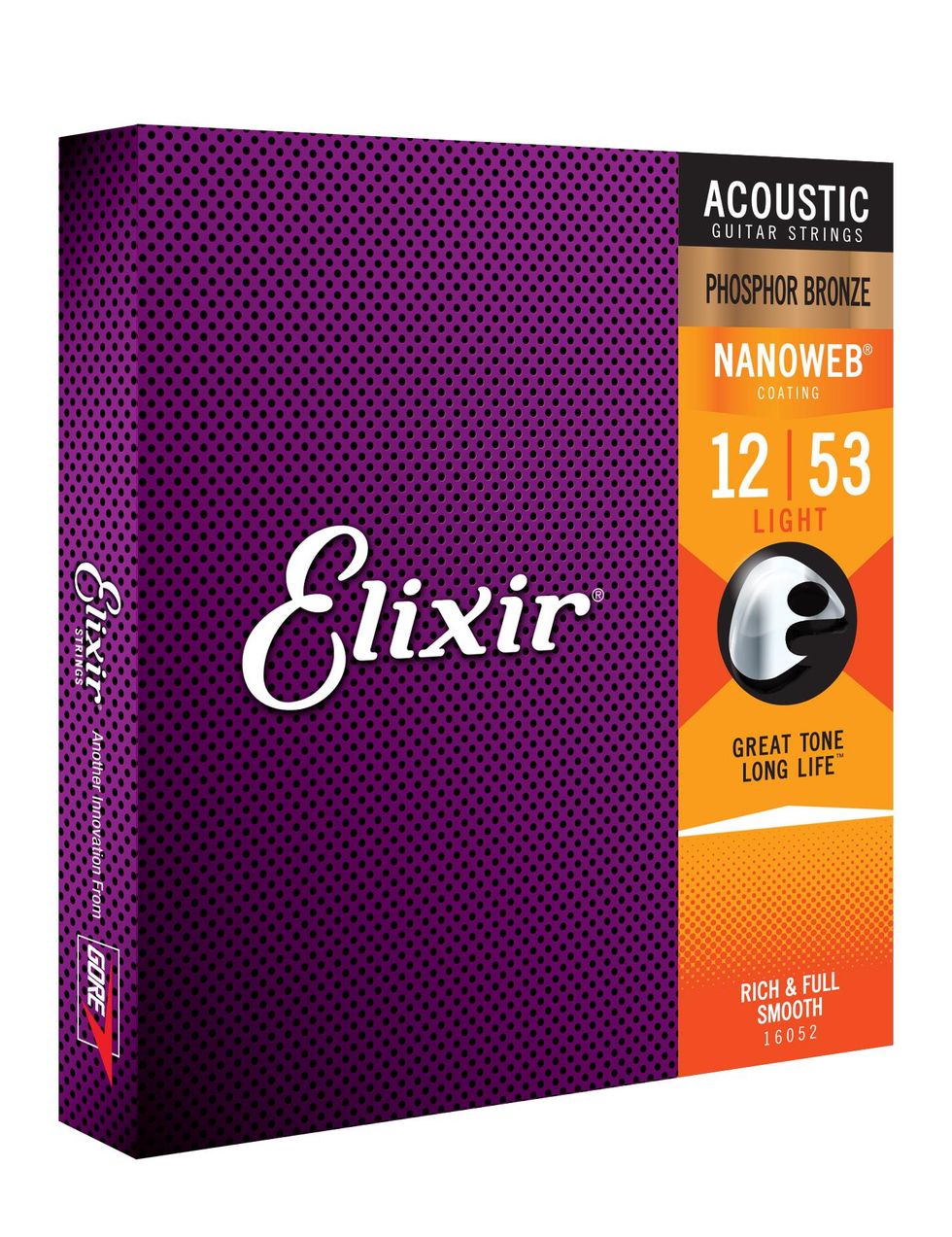
<p>Engineered for great tone and long life, our proprietary, featherweight coating keeps strings sounding and feeling new for longer. Tone-killing elements like corrosion, dirt, oil, and sweat are no match for Elixir® Strings.<br/><br/>Our Phosphor Bronze with NANOWEB® Coating is rich and full-bodied with sparkling high-end clarity and a smooth feel.<br/><br/>See a line up of all of our acoustic guitar strings here - https://www.elixirstrings.com/guitar-strings#acoustic</p>
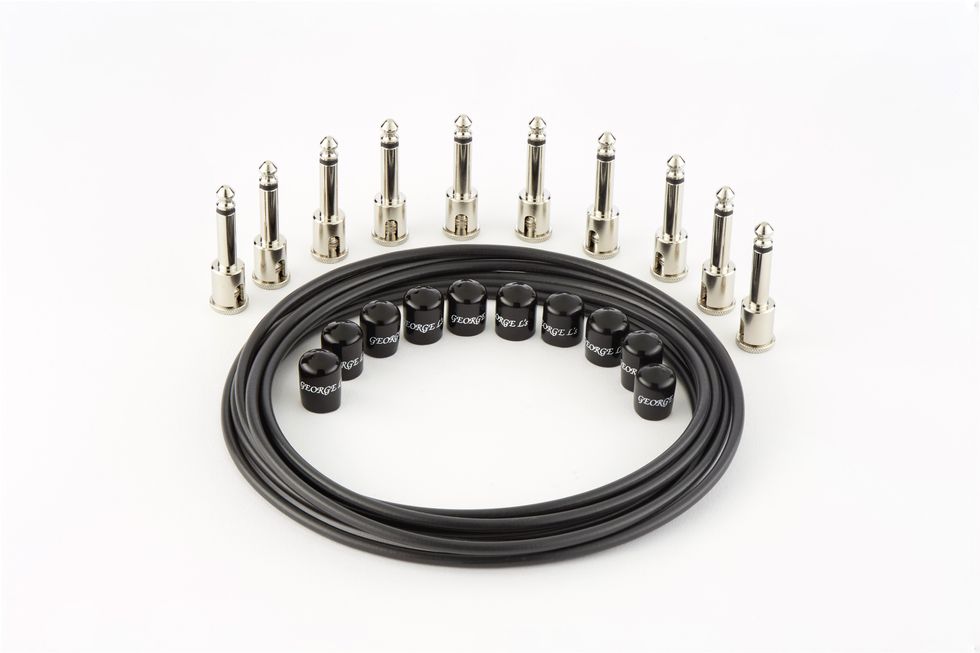
<p><strong>Revolutionary Design and Features:</strong><br/>Optimize your pedalboard layout with durable, snug fitting, strong and lightweight risers. Tailor your pedalboard to fit your stompbox collection and your style of playing!<br/><br/><strong>Space Saving, Easy Wire Routing:</strong><br/>Our riser footprint is virtually the same as the pedal for which it was designed. Whether it's <a href="https://www.premierguitar.com/tag/boss?utm_source=website&utm_medium=link&utm_campaign=Smartlinks">Boss</a>, Wampler, <a href="https://www.strymon.net/" target="_blank">Strymon</a>, MXR, Ibanez, Electro Harmonix, Walrus, Earthquaker Devices, TC Electronic, JHS or any of the popular pedals, our risers take up no more space than the pedal itself. An added benefit of the Elephant Foot design is the ease with which you can route signal and power cables. There's plenty of space under each riser and multiple attachment points for tie-wraps. <br/><br/><strong>Unique Features of Elephant Foot Risers</strong><br/>• Strong yet lightweight<br/>• Versatile<br/>• Cables route easily underneath <br/>• Anchor point for tie wraps <br/>• Hidden screw holes for a super-strong connection to either wood or metal pedalboards <br/>• Works with hook & loop, cloth cable ties or tie wraps<br/>• Unique Pedal "Frames" for your first row of pedals<br/>• Risers can be customized<br/>• 3D printed from eco-friendly PLA<br/><br/>Available in seven standard colors and custom colors available on request.<br/><br/><strong>Benefits of Elephant Foot Risers</strong><br/>• No more accidental pedal stomps <br/>• No annoying pedal wobble when stomping<br/>• No more sloppy pedalboards<br/>• Optimized Pedalboard layouts <br/>• Easy, neat cable routing<br/>• Custom riser sizes available in multiple colors<br/>• Preserve resale value of pedals</p>
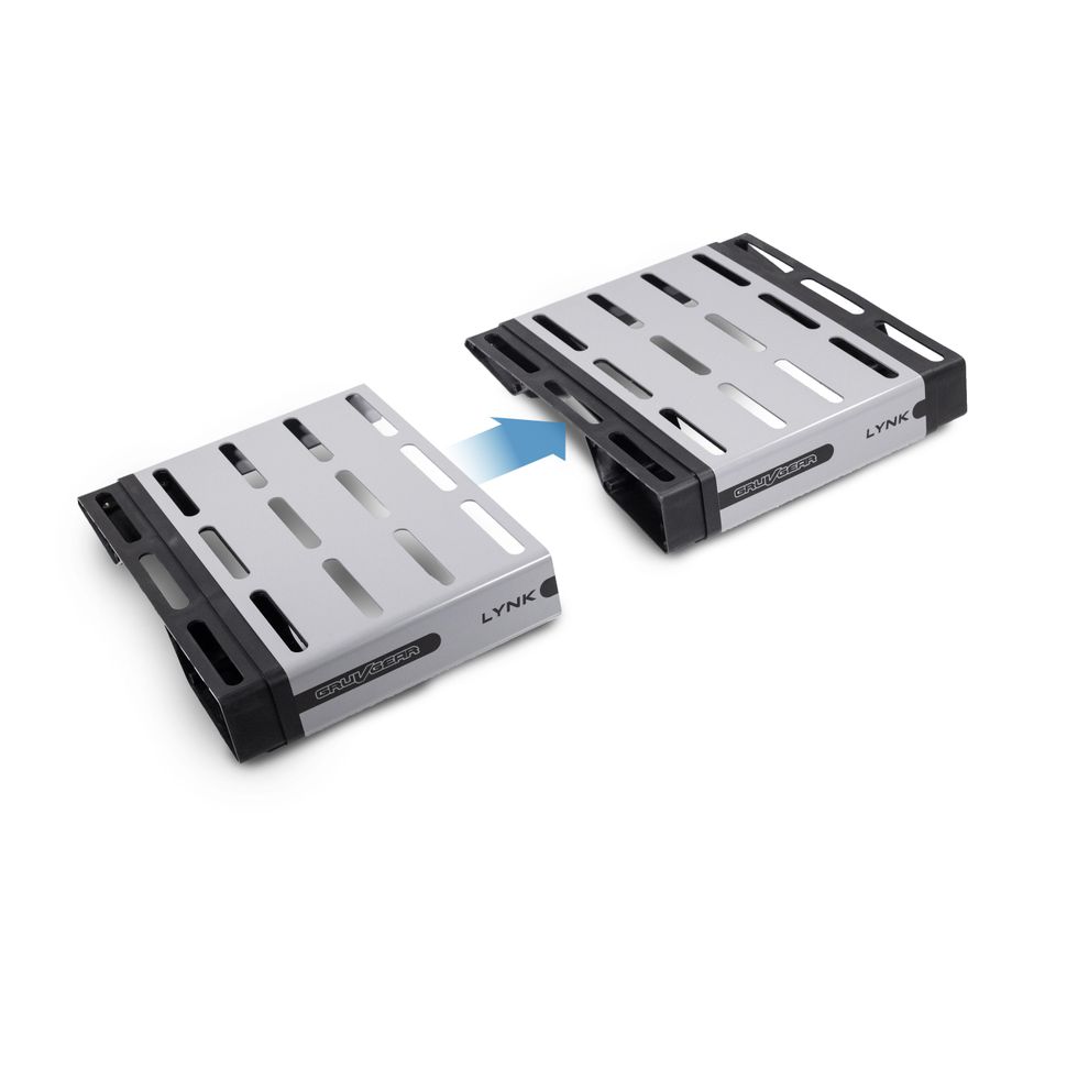
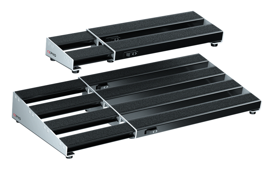
<p>XPND is the pedalboard that adapts to you. With XPND's patented telescoping technology, you can easily adjust the length of the board to add, subtract, and rearrange pedals how you want, when you want.</p>
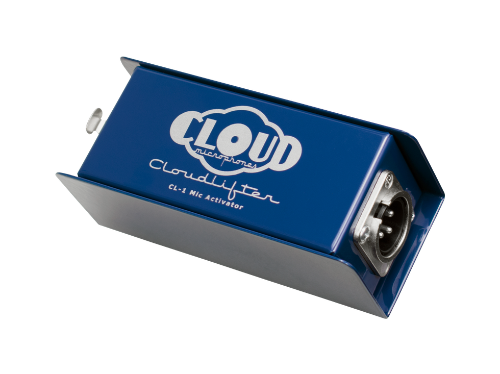
<p>The original Cloudlifter® Mic Activator® adds tons of ultra-clean gain to dynamic and ribbon microphones and are the perfect stocking-friendly gift for any musician (or yourself)! Made in the USA. Get Lifted. Get Gifted!</p>
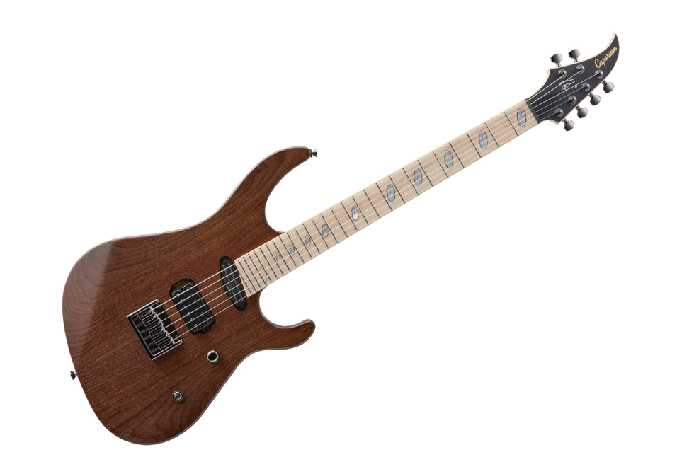
<p>The Horus-WB-FX is the latest model to be developed within the popular Caparison Horus range.<br/><br/>This newly designed fixed bridge version features a carefully considered body construction featuring a Walnut top and an Australian Blackwood back. This unique fusion produces a full rounded tone with a sweet emphasis on the upper mids ensuring clarity, focus and a distinct separation of notes, even with the most extreme gain-saturated down tunings.<br/><br/>When combined with an upgraded Caparison designed, sustain rich, high mass bridge (which effortlessly copes with a myriad of acute tunings and string gauges) Jescar jumbo stainless steel Frets and a specifically designed set of Caparison pickups, the Horus-WB-FX is more than capable of producing arena filling rock tones or creating more subdued, distinctively rich and bell like cleans.<br/><br/>The Horus-WB-FX plays like an absolute dream and features all of the beautiful aesthetic qualities that you have come to expect from Caparison Guitars. The striking body design is complimented by three stunning new finishes and also comes with a choice of either an Ebony or Maple fret board..</p>
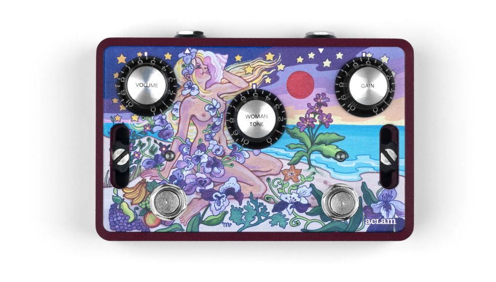
<p>The Woman Tone is Aclam’s tribute to Eric Clapton’s amazing sound during his Cream era. The sound that turned him into a god. An accurate approach to the unique tone he attained with a simple yet effective combination of a P.A.F equipped Gibson and 100W Marshall stacks all the way up.<br/><br/>- Eric Clapton's Cream Sound in a box:<br/>Aclam has distilled and bottled in a stompbox the key elements that shaped Eric’s rig. Reproduce his unique rhythmic and solo tones, fine-tuned using both live and studio recordings of Cream.<br/><br/>- Artwork by The Fool's Guitar artist: Marijke koger:<br/>Responsible for the psychedelic decoration of Clapton’s Gibson SG nicknamed “The Fool”, Marijke has created a unique artistic interpretation of the Woman Tone that looks stunning!<br/><br/>- Custom <a href="https://www.premierguitar.com/tag/humbucker?utm_source=website&utm_medium=link&utm_campaign=Smartlinks">humbucker</a> pickup simulation circuit & tone control:<br/>A pickup simulation circuit emulating the tonal characteristics of a P.A.F style pickup has been incorporated to reproduce the “Woman Tone”. With its buffered input, the guitar signal won’t be affected. Use compressors, fuzzes or whatever effect you want in front of the Woman Tone, and it will retain its tonal characteristics.<br/><br/>- Touch sensitive plexi-inspired overdrive using discrete components:<br/>Inspired by Clapton’s 100W full stacks it results in a powerful overdrive with a great British character! Designed having blues-rock in mind, it will perfectly suit any guitar player seeking a vintage tone!</p>
<p>A hot new gear company from Canada, Templo Devices jumped on the scene with their flagship lithium-battery powered amp aimed at electric guitarists.<br/><br/>Focused on creating problem-solving products with tonal excellence, they've since released several small-batch pedals with wide appeal. Including SPLYCE, a versatile mini-mixer for using a microphone with a guitar rig, the atmospheric TRIPLO modulation pedal and the REEL DEAL tape preamp, as well as their exciting upcoming release, the Pocket Studio Compressor. There is always something exciting coming from this northern innovator.<br/><br/>With plenty of great deals for the holiday season, they have a little something for everyone.</p>
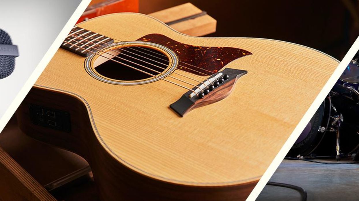
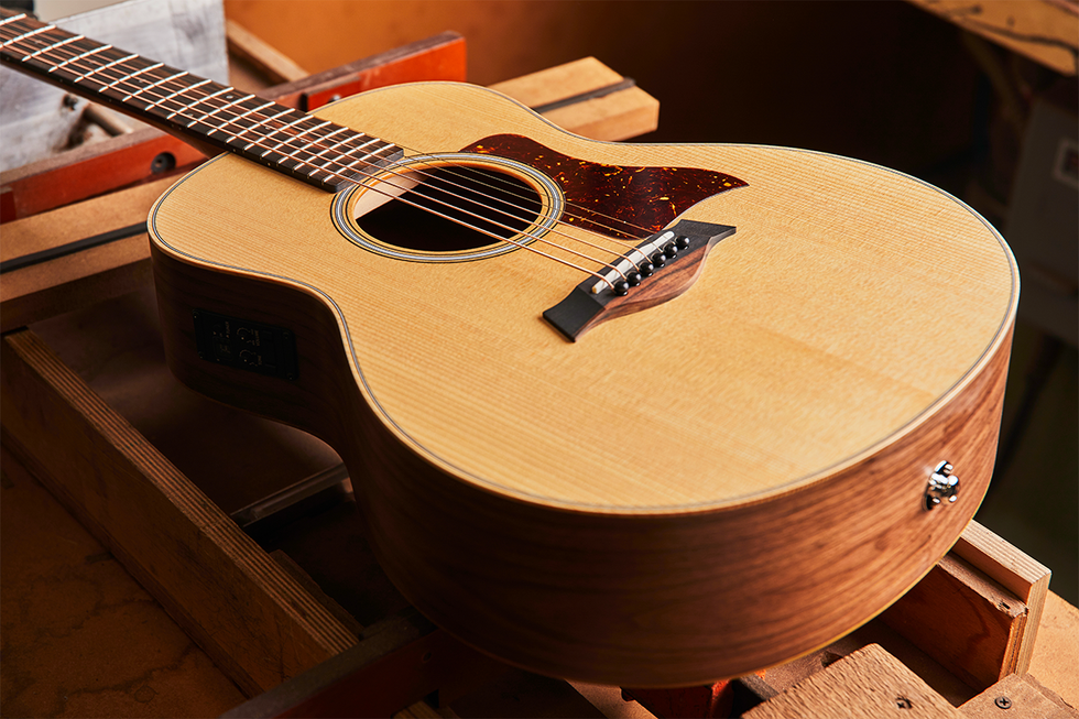
<p>Meet the Taylor GS Mini, one of the world's most popular acoustic guitars: a smaller body and a compact feel with a big, bold tone that punches far above its size. Based on a scaled-down version of our Grand Symphony body shape, GS Mini guitars boast solid tops and a variety of tonewood options serving up different flavors of vibrant acoustic tone. The GS Mini family is also home to the GS Mini Bass, a super-compact four-string acoustic bass with a slinky feel and a punchy response. Whether you're looking for a campfire guitar, a songwriting tool or just a great-sounding acoustic that's up for anything, the GS Mini has you covered.</p>
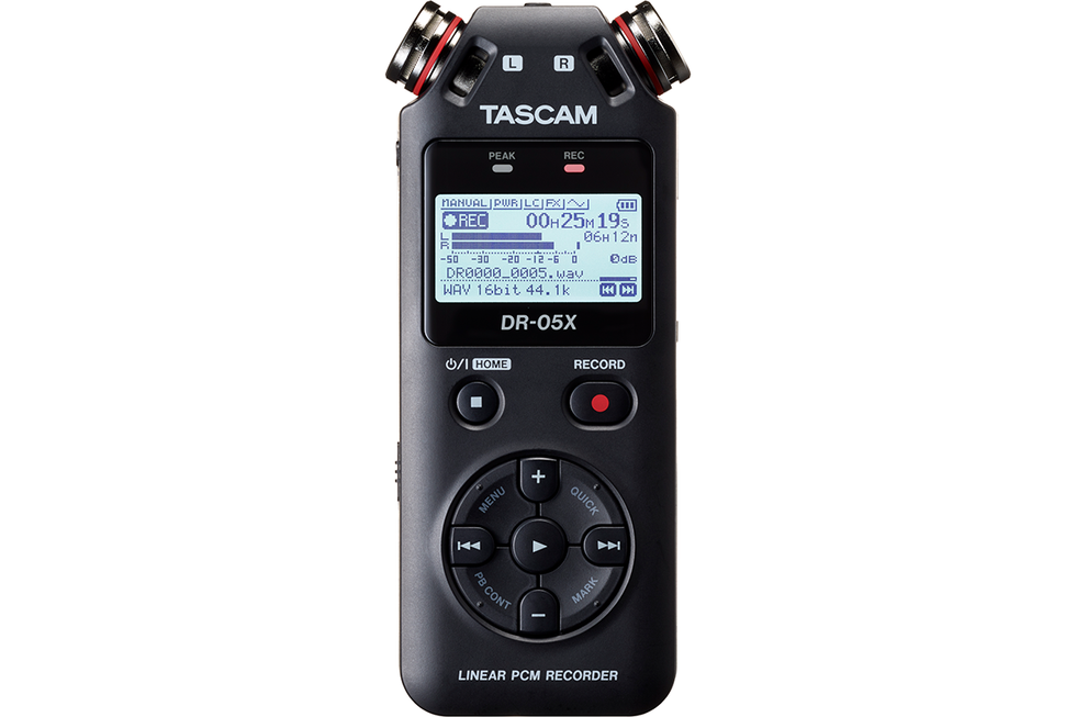
DR-05X Stereo Handheld Recorder
<p>The TASCAM DR-05X stereo handheld recorder is a great-sounding portable recording solution with helpful workflow options. Use the TASCAM DR-05X's built-in omnidirectional condenser microphones to capture vibrant stereo recordings anywhere, anytime. Use Auto Recording mode to automatically engage recording when audio signals reach a certain level. Use the Overwrite function to make easy punch-in audio replacements. Or use the TASCAM DR-05X as a 2-input/2-output USB audio interface with your Mac or PC. Whatever your portable 2-channel recording needs are, the TASCAM DR-05X has you covered. It's a fantastic and easy way to record your ideas, rehearsals, or gigs. Simply remove the SD card and pop it into your computer and send your song ideas to bandmates or collaborators. It's small enough to take with you everywhere and fits easily in a guitar case or small bag.</p>
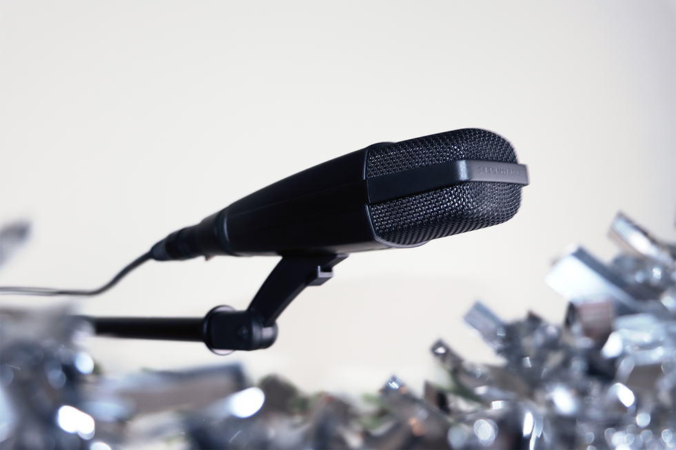
<p>MD 421-II<br/>The cardioid MD 421 has been one of Sennheiser’s most popular dynamic microphones for decades. The large-diaphragm, dynamic capsule handles high sound pressure levels, making it a natural for recording guitars and drums. The MD 421's full-bodied cardioid pattern and five-position bass control make it an excellent choice for most instruments, as well as group vocals or radio broadcast announcers. One listen and you'll know why it’s a classic.</p>
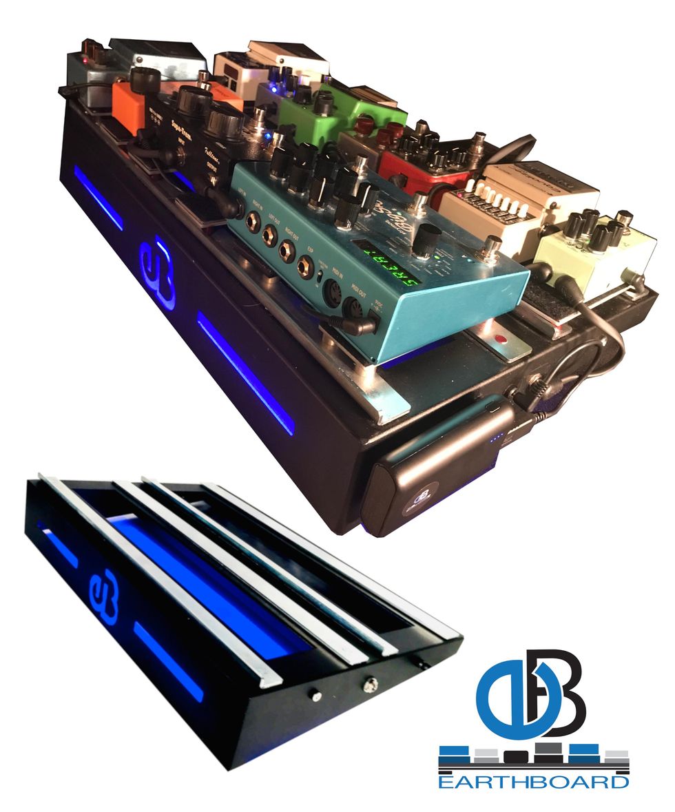
<p>Every once in a while, a product comes out that makes you go “Wait… WHAT?!?!”. Well, those words are music to our ears! This game-changing pedalboard allows you to power all your pedals, including pedals that need isolation and different voltages, with a single power source. Yep, either our rechargeable battery or AC adapter fires up all your pedals without additional power bricks. No more Velcro carpet to rip pedals off! You can literally change pedals on the fly. But the flexibility of EARTHBOARD doesn’t end there – Our Lifeline Tether carries power off the board to connect a WAH, or daisy-chain multiple EARTHBOARDs together. EARTHBOARD comes in 2 sizes: double row (holds 12 standard size pedals) and single row (holds 6 standard size pedals). They are available as Complete Pedalboard Systems (includes all necessary components to play) or as a Build-a-Board and "ala cart" accessories!<br/><br/>See video: <a href="https://www.youtube.com/watch?v=S3iwDgLnN6w&t=8s" rel="noopener noreferrer" target="_blank">https://www.youtube.com/watch?v=S3iwDgLnN6w&t=8s</a></p>
<p>
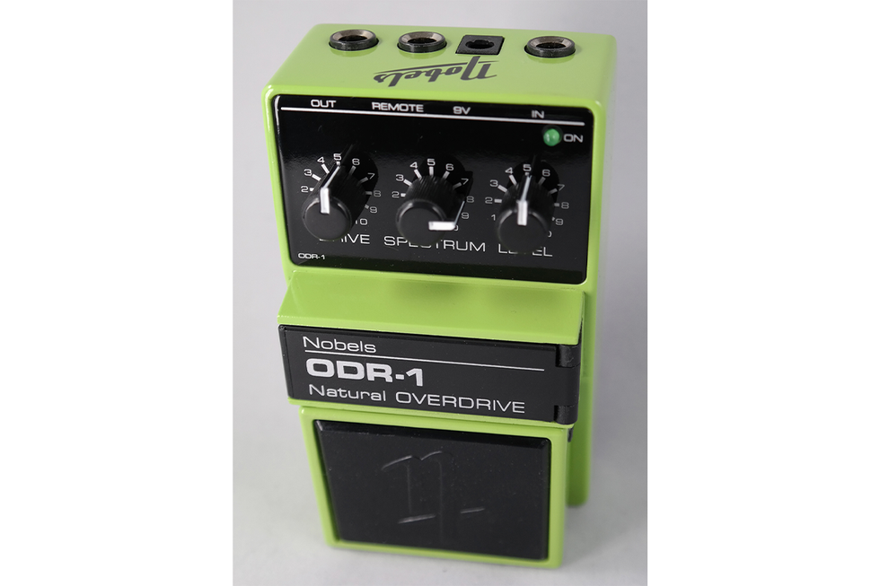
The Nobels ODR-1(bc) has bass cut, 9-18 volt input, and glow-in-the-dark knobs. The ODR-1 is rated the best overdrive by Nashville studio guitarists and creates a natural, tube-amp style overdrive that is versatile, amp-like, and affordable. The ODR-1 has been on the market for over 30 years and remains the number one choice. Creates crunchy rock and blues sounds or extra boost for soloing without smothering the natural character of your guitar's tone. The Spectrum controls optimizes tones from single coil chime to powerful humbucker rock. When adjusting the Spectrum control up or down the circuit ensures you have plenty of clarity and full dynamic range.<br/>
<br/>
Features<br/>
Bass cut switch<br/>
Spectrum Control<br/>
Glow-in-the-dark knobs<br/>
Solid metal chassis<br/>
Nobel's remote control jack switching system<br/>
German Engineering. Made in China.<br/>
<br/>
<a href="https://nobels.de/wp-content/uploads/Nobels-ODR-1-60s-Woman-Tone-Jerry-Donahue-HELLECASTERS-two-1-albums-Billboard-USA.mp3?_=1" target="_blank">Click here for Audio Clips<br/>
</a>
</p><p><a href="https://youtu.be/tDWl72Eam0A" target="_blank">Click here for Video Clips</a></p>
<p>Modeled after Orangewood’s full-size Oliver guitar, the Oliver Jr. is a scaled-down version of Orangewood’s best-selling grand concert model. But don’t let the small body fool you. Sporting a beautiful, woodsy solid mahogany top, this junior guitar sings a bold and bright tone that’s easy to love. Whether you’re looking for your new travel companion or simply want a compact guitar to live near your couch, you can’t go wrong with this perfect-sized guitar.<br/><br/>Prefer a full-size model? This holiday season, every Orangewood guitar includes a professional set up and free shipping right to your door with a premium gig bag included. Plus, get extended holiday returns until January 31st. That’s over 60 days of commitment-free playing, so you can gift a guitar that they’re sure to love.</p>
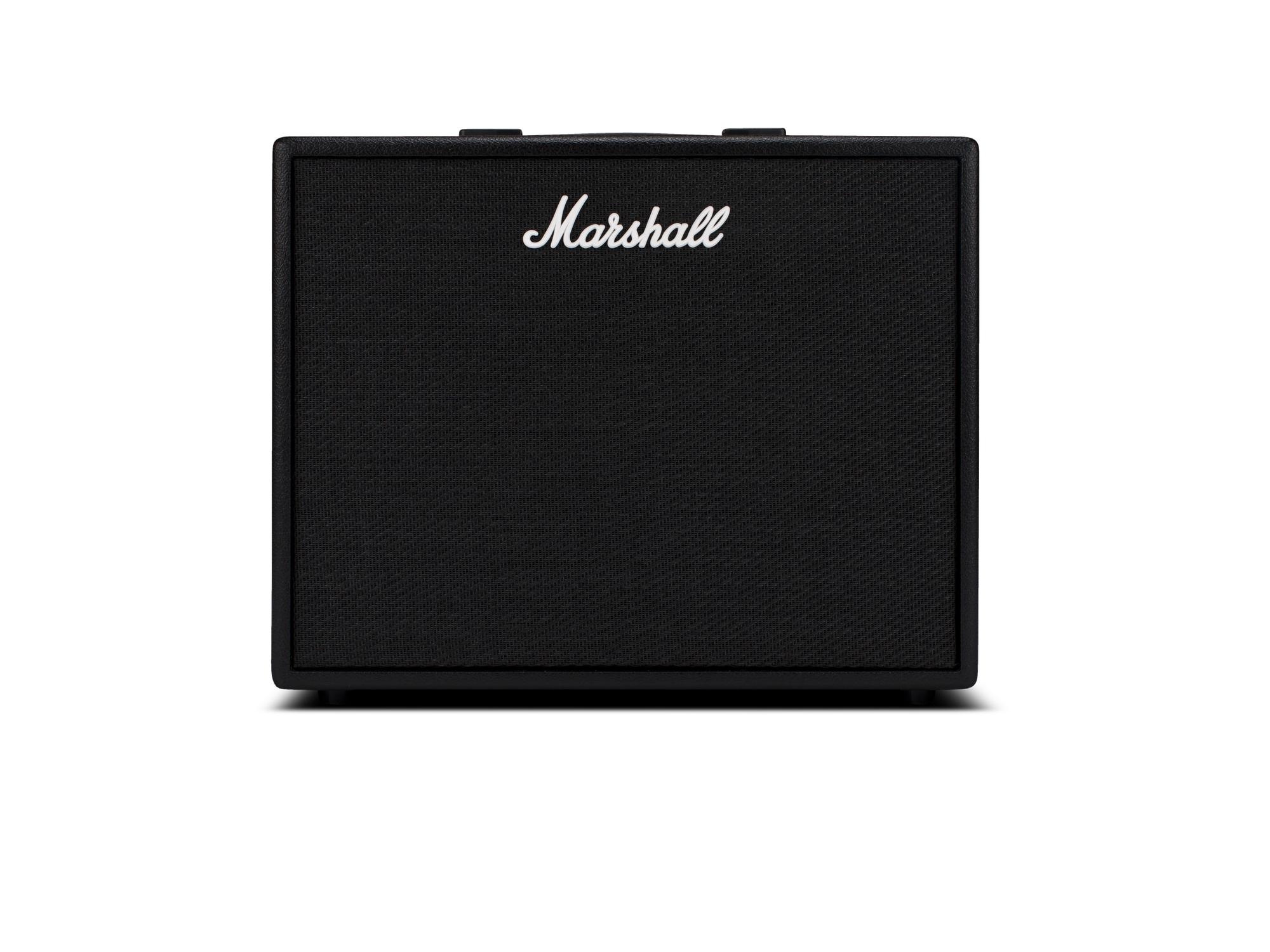
<p>Jump straight in and explore 100 presets, the CODE50 has all you need to start performing and recording with. 50W of power that’s portable enough for you to practice at home or in the garage. Sync with your phone or online so it’s always with you for those creative moments. This fully digital amp is loaded with 14 MST preamps, 4 MST power amps and 8 MST speaker cabinets for you to create sounds that suit you. Using the Gateway App you can connect via Bluetooth to control CODE and stream music from your iOS or Android device. MyMarshall has a global library of user presets that you can upload to and download.</p>
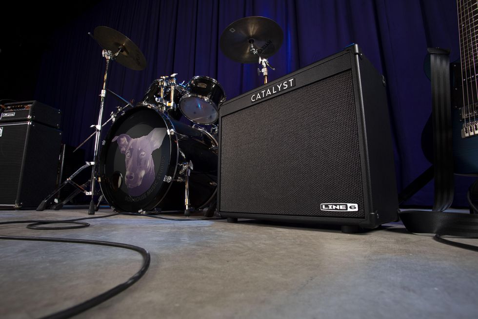
<p>Catalyst® 100 is a 100-watt, dual-channel 1x12 combo amplifier that performs like a traditional guitar amp—while providing the increased versatility of a modern amp. Catalyst 100 offers six Original Amp Designs—ranging from pristine clean to modern high-gain—crafted using our renowned HX® sound design techniques to ensure exceptional tone and feel. Ideal for stage or studio.<br/>• 100-watt, dual-channel 1x12 combo amp (with optional LFS2 footswitch)<br/>• Catalyst 100 operates like a traditional amp—but provides increased versatility<br/>• 6 Original Amp Designs—pristine clean to modern high-gain<br/>• Dedicated Boost and Reverb sections (6 reverb types), 18 Effects (3 types)<br/>• Power attenuator (half power, 0.5 watts, Mute) for reduced volume<br/>• XLR line output for pro connection to P.A. or recording devices<br/>• Effects loop and Power Amp input for integrating external devices<br/>• MIDI In via DIN connector</p>
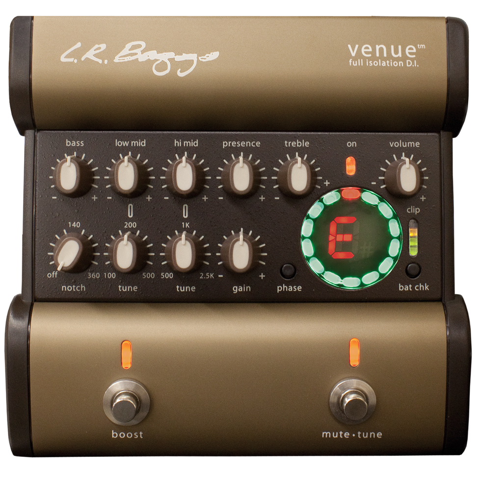
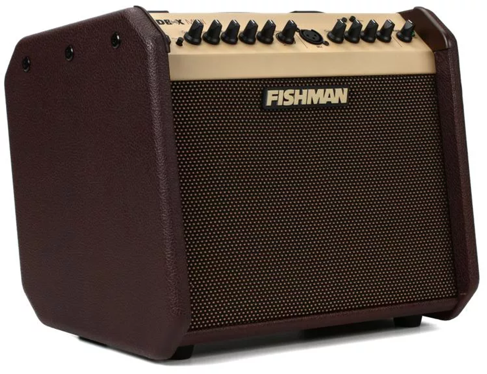
<p>Every Tool You Need in One Acoustic Pedal<br/><br/>We created the Venue DI so you can travel light, set up fast, and sound incredible anywhere you plug in. The Venue DI gives you complete control by combining a full-isolation DI output, 5-band EQ with adjustable low & hi-mid bands, variable clean boost, and chromatic tuner all in one acoustic pedal. With its all-discrete signal path, hi-graded semiconductors, and exclusive use of audiophile grade film capacitors, the Venue DI is on par with the world’s elite preamps and provides a studio quality sound for the stage.</p>
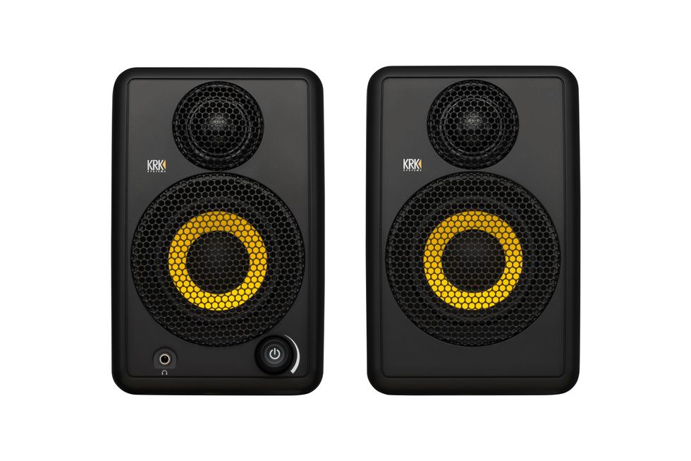
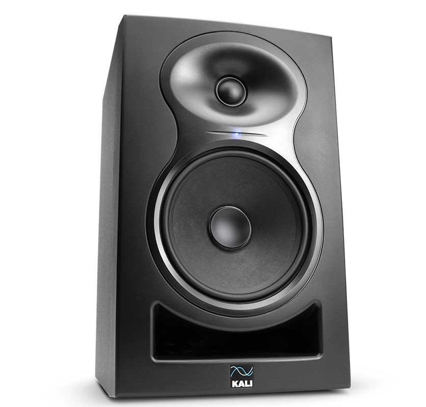
<p>The LP-6 V2 is Kali's best-selling studio monitor, and it's made its mark in studios across the globe ranging from humble home setups to state-of-the-art recording facilities.<br/><br/>Kali's innovative 3-D imaging waveguides create a crystal-clear stereo image, and also help the speakers to perform their best in challenging acoustic spaces. Kali-programmed boundary EQs take this a step further, tailoring the sound of the speaker for its placement on stands, on a desk, or close to walls.<br/><br/>With accuracy and translation at the forefront, the LP-6 delivers transparent, full sound that gives you a complete picture of your mix. Whatever you mix on the LP-6, you can be sure that it will translate nicely to other speakers, earbuds and headphones, car systems, or whatever else your listeners are using for playback.</p>
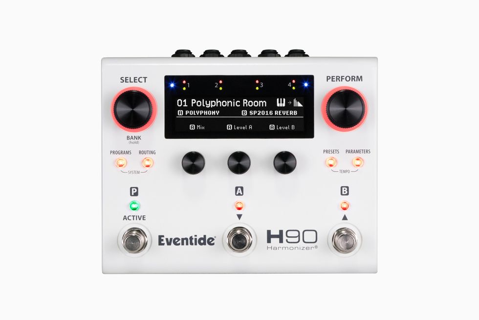
<p>The H90 Harmonizer® is Eventide's next-generation multi-effects pedal. Whether you want high-quality bread and butter effects or experimental sounds unheard, the H90 has everything you need to inspire your creativity with an intuitive UI designed with players in mind. Discover why top artists and producers have chosen Eventide through the years with 62 effect algorithms and hundreds of Program combinations curated for a variety of instruments and genres. With its comprehensive I/O and flexible routing options, the H90 is designed to be the heart of your rig.</p>
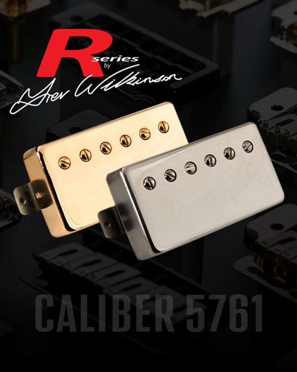
Wilkinson R Series Trev Wilkinson Signature Pickups
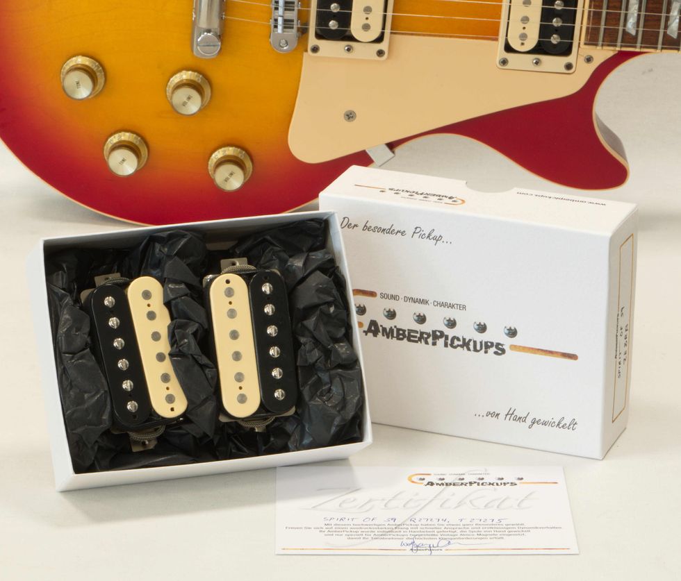
<p>Wilkinson's R series range of pickups are the result of Trev Wilkinson's years of creating and listening to thousands of pickups. Time spent with legendary and iconic individuals such as Seth Lover and Leo <a href="https://www.premierguitar.com/tag/fender?utm_source=website&utm_medium=link&utm_campaign=Smartlinks">Fender</a>, with whom Trev questioned about all aspects of sound, construction materials and production methods. All this combined knowledge has been the template for the R Series range of pickups, a pickup range Trev is proud to place his signature on, and say " These are the finest pickups Wilkinson has produced in the history of the company".<br/><br/>Featuring Single Coil's for both S and T style guitars, P90 and Humbucker models, the R Series has era specific models to capture the tone and vibe of the time and the players that influenced generations of players and Hybrid designs to influence future players.</p>
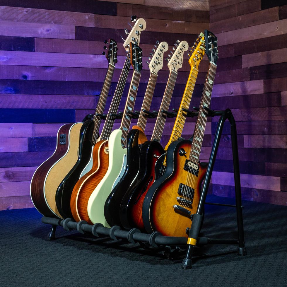
Hercules Stands Five-Piece Guitar Rack with Two Free Expansion Packs
<p>For a limited time only, get two FREE expansion packs with the purchase of a five-piece guitar rack. Showcase your collection while safely and securely storing seven to ten guitars. The Hercules GS525BP-HA205 is covered with Specially Formulated Foam rubber at all contact points and features a one-piece design that sets up and tears down easily. The guitar yoke is designed for acoustic, electric, and bass guitars with four pick slots on each yoke. This special pack comes with a total of seven guitar yokes leaving room to expand to ten. Available while supplies last.</p>
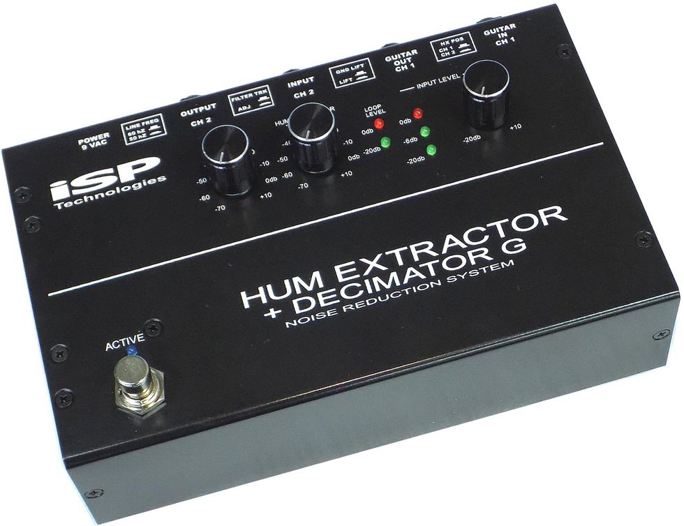
<p>Ultimate DSP 2 channel noise reduction pedal. Patented technology that will remove the 50Hz or 60Hz and all associated hum harmonic components with total transparency. Combined with the patented Decimator G technology and dynamic sliding low pass filter, the Hum Extractor is the pinnacle of noise reduction technology. The Hum Extractor technology is dynamic in operation which compares the level of the audio signal to the hum harmonic components. Dynamically removes hum components when they become dominant. Made in the USA.<br/><br/><a href="https://www.youtube.com/watch?v=q88JKgk9gCc" target="_blank">Click here for video</a></p>
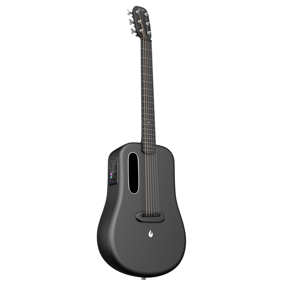
<p>With the multi-touch display integrated with HILAVA OS, the LAVA ME 3 provides easy access to play and customize tons of built-in effects and loops.</p>
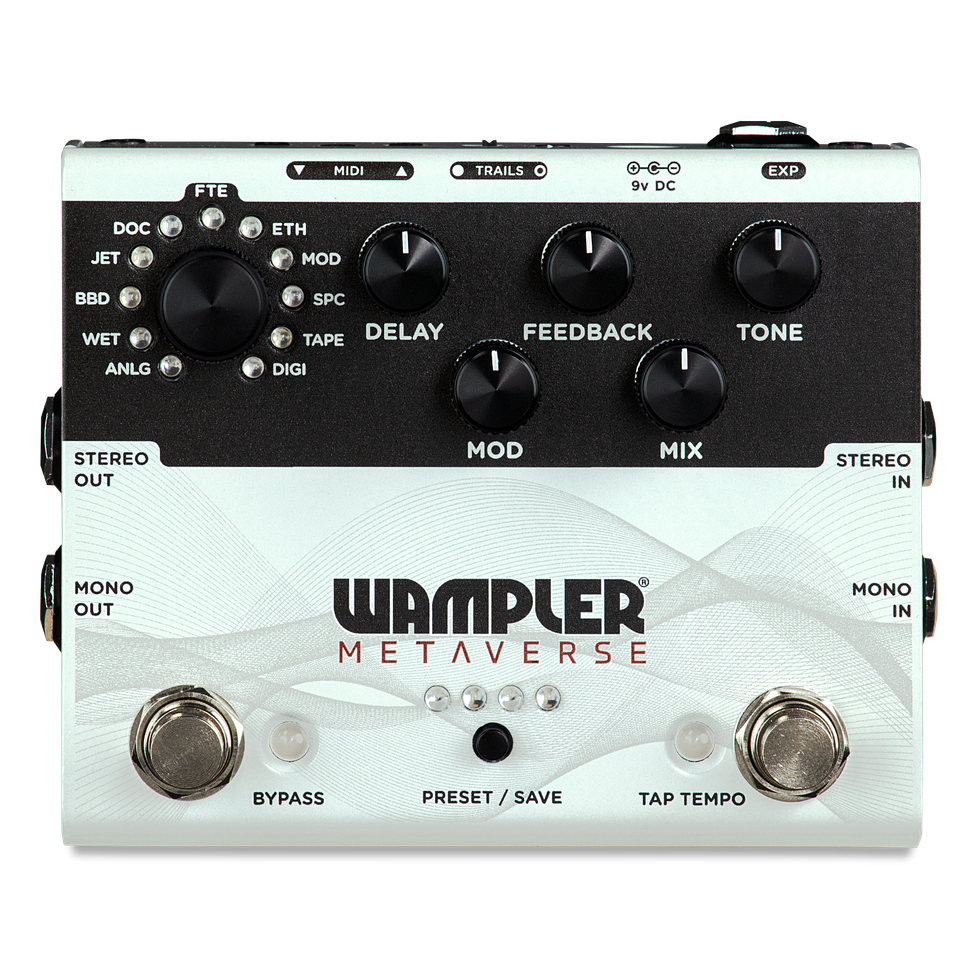
<p>Comprising eleven of Brian Wampler’s favorite delays, the Wampler Metaverse is a full-featured, small-footprint multi delay stomp box that is fully programmable, preset capable, has stereo inputs and outputs, allows full MIDI control, and has an expression input that you can assign to ANY of the parameters. The Metaverse also comes with a software version of the pedal via a set of 11 AU and VST3 plugins compatible with most popular DAWs - FREE to all customers that register their Metaverse online.<br/><br/>• Studio quality conversion 48 kHz Sampling rate with 24-bit audio<br/>• Full 20Hz to 20kHz frequency response<br/>• 11 Studio-quality vintage and modern delay effects<br/>• Simple user interface<br/>• All parameters controllable via an outboard expression pedal<br/>• 8 onboard preset locations to save your favorite patches, 128 total via MIDI<br/>• Full MIDI control with CC and PC commands<br/>• Stereo or Mono I/O</p><p><a href="https://www.youtube.com/watch?v=W85mzG5Czac" target="_blank">Click here for video</a></p>
<p>Gator's Transit Series acoustic gig bags provide rugged case-like protection without sacrificing the lightweight portability of a bag. The red soft-lined interior and thick foam padding safeguard your guitar from drops and bumps, just like a regular case. A weather-resistant blended fabric exterior protects against the elements and features backpack straps, each with a concealable zipper pocket to switch between backpacking and briefcase carry modes. So for the gear you love the most, Guard it with Gator.</p>
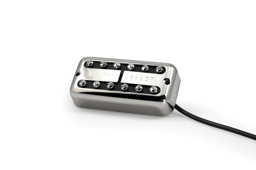
<p>Experience exceptional clarity and articulation in a Filter’Tron format with Lindy’s unique Fralin’Tron design. Featuring a focused single-coil vibe with a rich, warm midrange and crisp attack, you’ll wonder where this pickup has been all your life. When Lindy started designing the Fralin’Tron, he did so with a particular goal: to get as much clarity and articulation as possible out of this design.We’re thrilled with the result! Our Fralin’Tron features a scooped midrange and defined bass and highs. In addition, you can expect more nuance out of the wound strings, unlike the original design. Furthermore, the treble strings have a round, warm quality, making our Fralin’Tron perfect for all styles of music – from clean to dirty. Lastly, this pickup features a dynamic and punchy attack that gives you back what you put into it.</p>
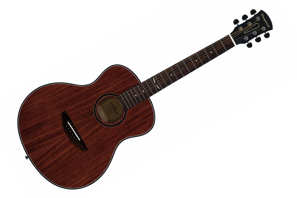
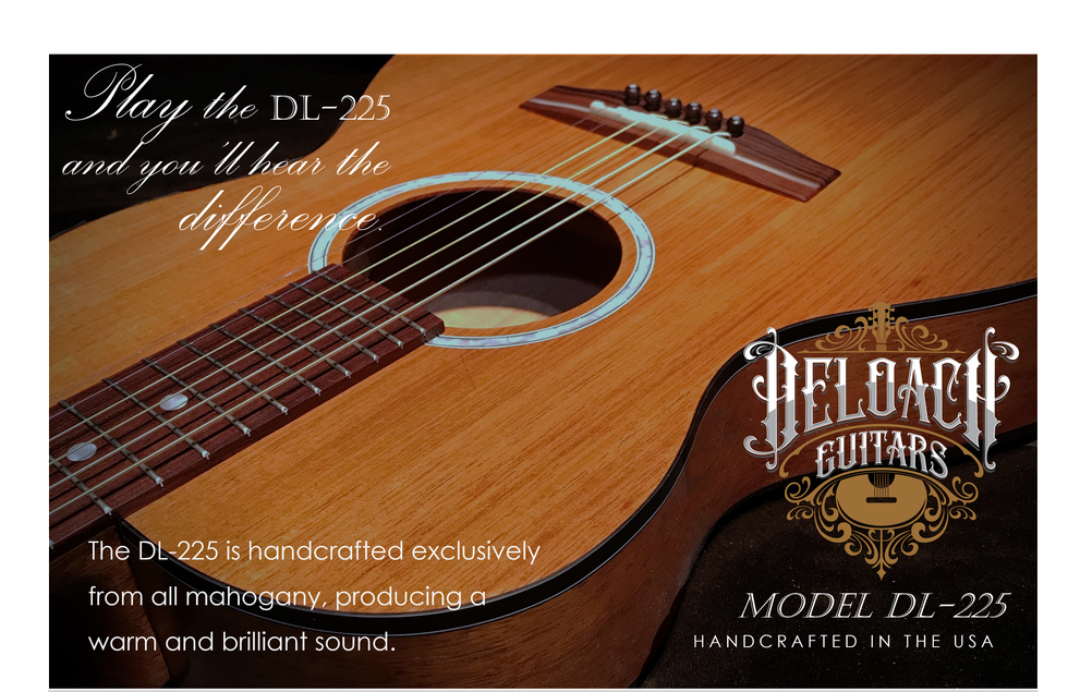
<p>The DL-225 is handcrafted exclusively from all mahogany, producing a warm and brilliant sound. The soundboard of the DL-225 features a vintage bracing pattern resulting in outstanding projection and tone with brilliant highs, strong midrange and subtle but full bass. The DL-225 has an extremely bright and dynamic sound. This guitar has the sound of a large body guitar. In a fingerpicking demonstration comparison we did with a name brand dreadnought the DL-225 was +3 dB louder.<br/><br/>Its smaller size and depth make the DL-225 a very comfortable guitar to play.<br/><br/><a href="https://www.deloachguitars.com/soundsample" target="_blank">Click here for video and audio examples</a></p>
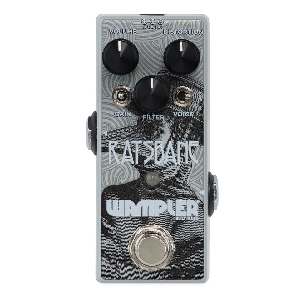
<p>If you are looking for a single pedal solution with multiple degrees of gain from light overdrive to full out saturated fuzz tones, then you’ll surely love the Ratsbane. The Ratsbane is based on a true benchmark sound amongst guitarists that has been heard on thousands of famous recordings.<br/><br/>In typical Wampler fashion, Brian improved the circuit’s flexibility by adding two new switches. The Gain switch offers three distinct choices. In the middle gives you the “stock” gain for this pedal. The left position offers a firm, yet smooth boost in gain, whereas the right delivers an insane level of creamy distortion. The Voice switch subtly alters the compression and clipping of this pedal. It tightens the distortion to be more manageable with greater levels of gain, while rolling back some of the fuzz qualities, to deliver a modern, high gain distortion.<br/><br/><a href="https://www.youtube.com/watch?v=IAt-hgqrocI" target="_blank">Click here for video clips</a></p>
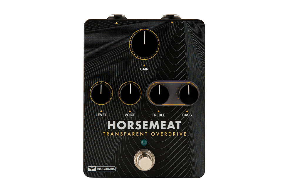
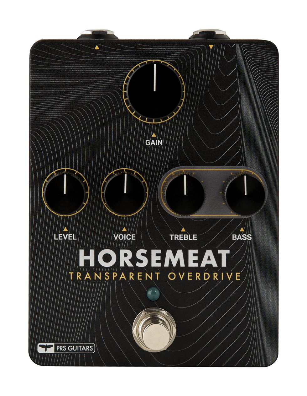
<p>The PRS Horsemeat transparent overdrive pedal is designed to enhance your sound without coloring your tone. Horsemeat adds harmonic midrange richness and overdrives without cutting out your high notes – all while giving you more available headroom. It features a robust EQ section so you can dial in your tone and has a wide range of gain on tap. Depending on the setting, Horsemeat can be used as a clean boost, straight overdrive, or even enhance your amplifier’s distortion by slightly pushing the front end of the amplifier’s preamp section.PRS pedals were created to be high-end pieces of audio gear. Designed by PRS Guitars in Stevensville, MD, USA. Made in the USA.</p>
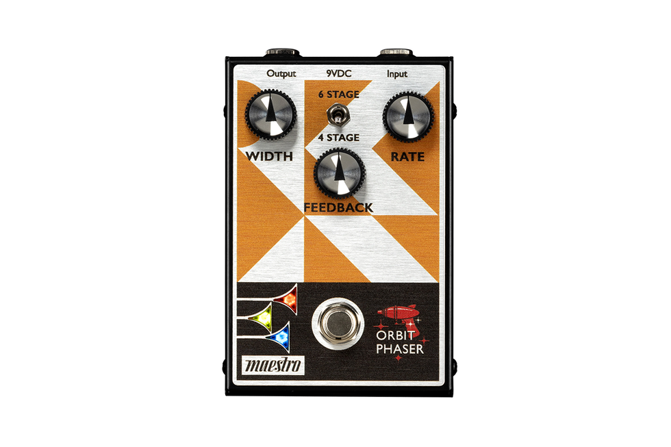
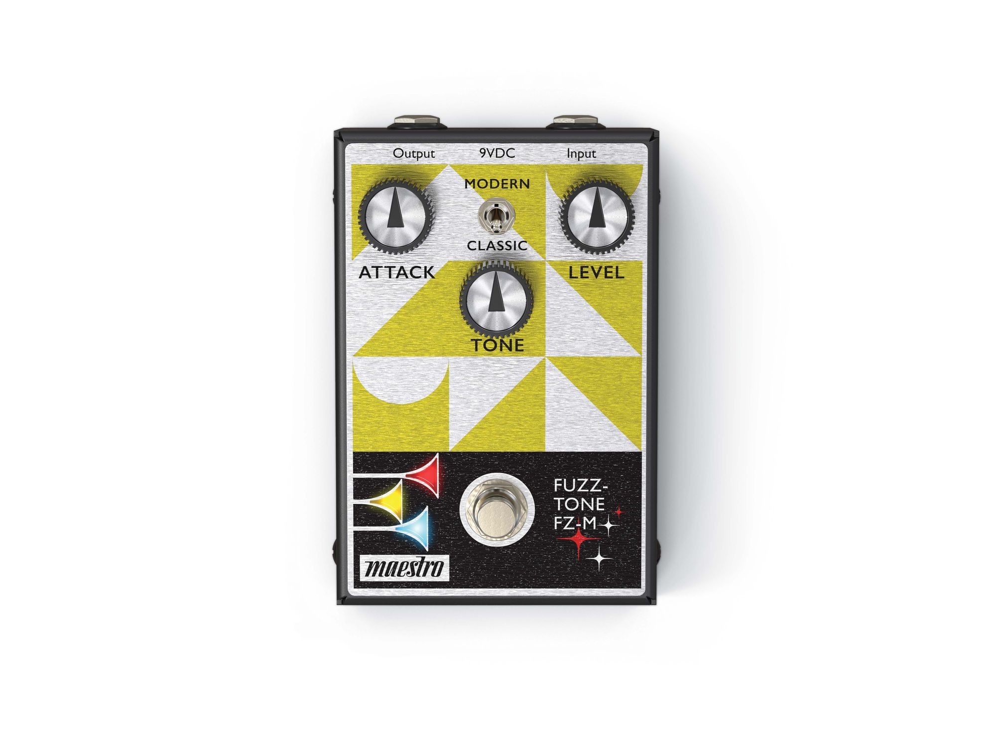
<p>Maestro created the world’s first fuzz pedal – the Maestro Fuzz-Tone FZ-1. Introduced in 1962, the Fuzz-Tone became the sound of rock and roll and a must-have accessory for guitarists everywhere after the success of 1965’s (I Can’t Get No) Satisfaction by the Rolling Stones, which prominently featured its cutting edge sound. Now Maestro is bringing the fun and sonic fury of those early Fuzz-Tones back with the new Maestro Fuzz-Tone FZ-M. This all-analog pedal boasts a Mode toggle switch that provides two pedals in one functionality for increased sonic versatility with both an FZ-1 inspired fuzz sound and a thicker, more modern fuzz tone. Its 3-knob control layout gives you intuitive control. The Attack knob controls the amount of fuzz. The Tone control lets you adjust the timbre from bright and raspy to warm and wooly and anywhere in between.</p>
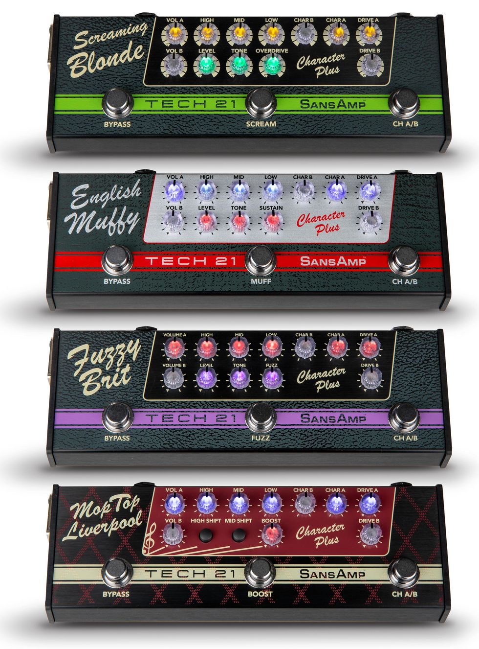
<p>The SansAmp Character Plus Series celebrates the unique chemistry between specific historic amplifiers and specific historic pedals, and cleverly unites them together in single packages:<br/></p><ul><li> <strong>Screaming Blonde</strong> = Fender-style + Tube Screamer-style</li><li> English Muffy = HiWatt-style + Big Muff-style</li><li> Fuzzy Brit = Marshall-style + Fuzz Face-style</li><li> Mop Top Liverpool = Vox-style + Rangemaster Booster-style</li></ul><p>Each of the individually-voiced Character controls sweep through an entire spectrum of eras within their particular amp style. Screaming Blonde tones range from the ‘50s Fullerton to blackface and silverface. The English Muffy spans from classic UK rock to prog rock. Fuzzy Brit goes from classic hard rock to all current rock genres. The Mop Top Liverpool embodies the British invasion through “Bohemian” rock.</p><p>These 2-channel multi-function pedals are each like having a stompbox within a stompbox. You can use the SansAmp amplifier emulation on its own or just the effect on its own. The all-analog SansAmps Character Plus Series pedals can be used as stand-alone pre-amps to drive a power amp, a studio mixer, or a PA system, or to complement your existing amp. Other features include built-in speaker simulation individually tuned to match each of the speaker/cabinet configurations associated with each amplifier type; 3-band active EQ, XLR Output, included 9V DC Power Supply. Rugged all-metal housing measures 7.75”l x 2.5”w x 1.25”h and weighs just 12 oz.</p>
<p>Never before has an effects pedalboard been so effortless to build and painless to change or rearrange on the fly - So you can Focus on the Music, Not the Set-Up!<br/><br/>Our game-changing design incorporates Rare Earth Magnets ("cupped" so there is no risk to your pedals!) and a long-lasting Battery to give you the neatest, cleanest sounding and looking rig! All of the hassles of using a traditional board are gone. No more messy cobweb of cords and cables. No need to look for outlets and extension cords. No need to deal with dirty noise at gigs. Increase voltage and isolate those "picky" pedals without adding more mess and expense of separate power bricks and adapters. NO MORE SOUND OF RIPPING VELCRO!!!<br/><br/>Here's what's possible with EARTHBOARD:<br/>- Your choice to use our Battery or AC Adapter<br/>- Jacks are on both sides to accommodate YOUR style and the unknowns of the gig space<br/>- All of our power supplies have built in circuit protection to safeguard your pedals<br/>- Built-in cross board audio patch cable saves you money and the hassle of finding the right length cable to connect your top and bottom rows of pedals<br/>- Ability to power large pedals off the board to maximize board real estate - make room for one more pedal!<br/>- The built-in, under mounted, Blue LED lights enhance visibility and the "cool factor"<br/>- Daisy-chain multiple boards and power them all with a single battery<br/>- Rearrange or add pedals on the fly, between sets, in a matter of seconds</p>
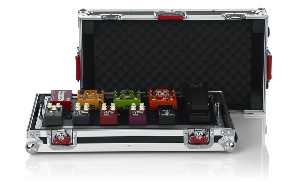
Large tour grade pedal board and flight case for 10-14 pedals with removable 24″x11″ pedal board surface and inline wheels
Features: Pro-grade shock absorbing EVA foam interior Removable pedal board surface 24" x 11" Two (2) rubber-gripped handles for easy lifting in and out of the case 3M Dual Lock» hook and loop fastener for pedal installation Cable and accessory storage under the removable pedal board Retractable tow-handle and inline wheels Plywood construction with aluminum edging to create a secure closure between lid and base Protective ball corners at vulnerable points Commercial grade Gator red signature hardware Lockable latches Spring-loaded rubber gripped handles
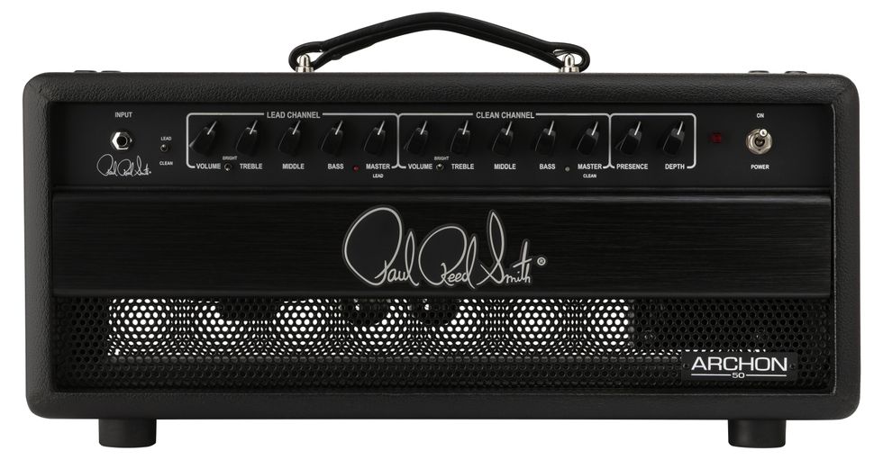
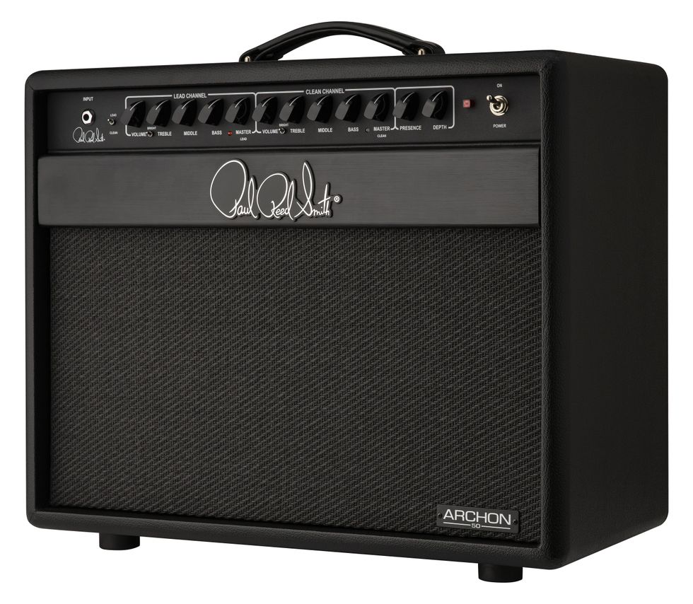
<p>Greek for “ruler” or “lord,” the <a href="https://www.premierguitar.com/tag/prs?utm_source=website&utm_medium=link&utm_campaign=Smartlinks">PRS</a> Archon is a commanding 2-channel amp with versatile overdriven tones and sparkling cleans with plenty of headroom. Designed with five gain stages before the master volume, the Archon’s lead channel is voiced to cover everything from Classic Rock to Metal with full, lush distortion. The clean channel provides rich tones that retain clarity even at high volume, and there is ample headroom, creating an excellent platform for pedals. The Archon has remarkably responsive tone with incredible note separation, whether you’re playing on the clean channel or chugging on the lead.</p><p>The PRS Archon is powered by two 6CA7 power tubes, which fall between EL34 and 6L6 tubes, offering the best of both worlds. 6CA7’s are warm, full, and articulate with smooth high end and tight low end. They chug, distort, and get heavy without over-saturating, and they sing without becoming harsh.</p>
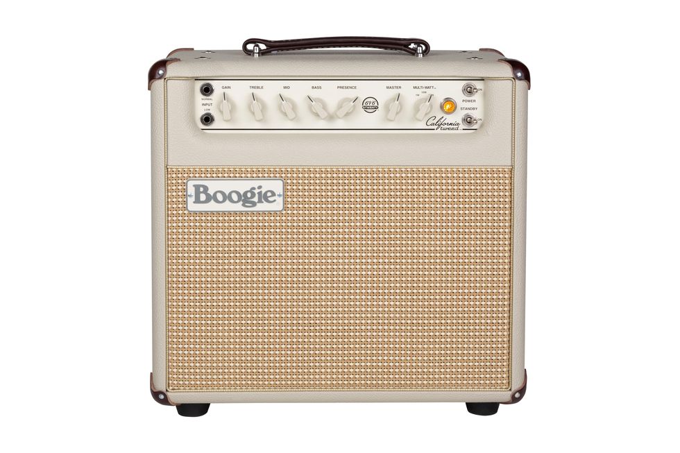
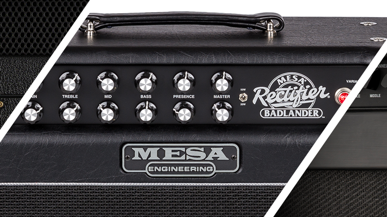
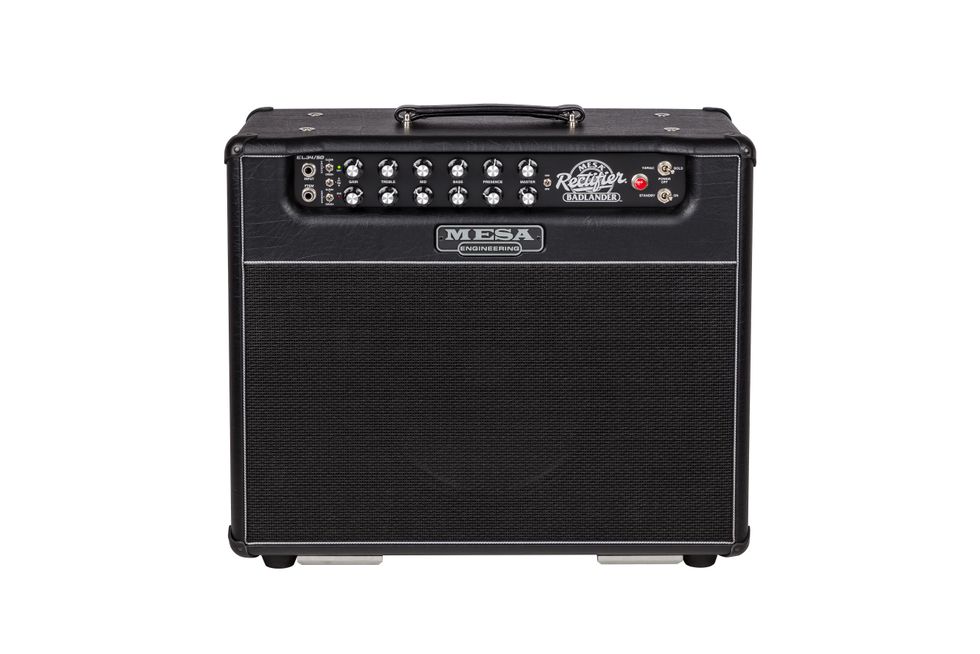
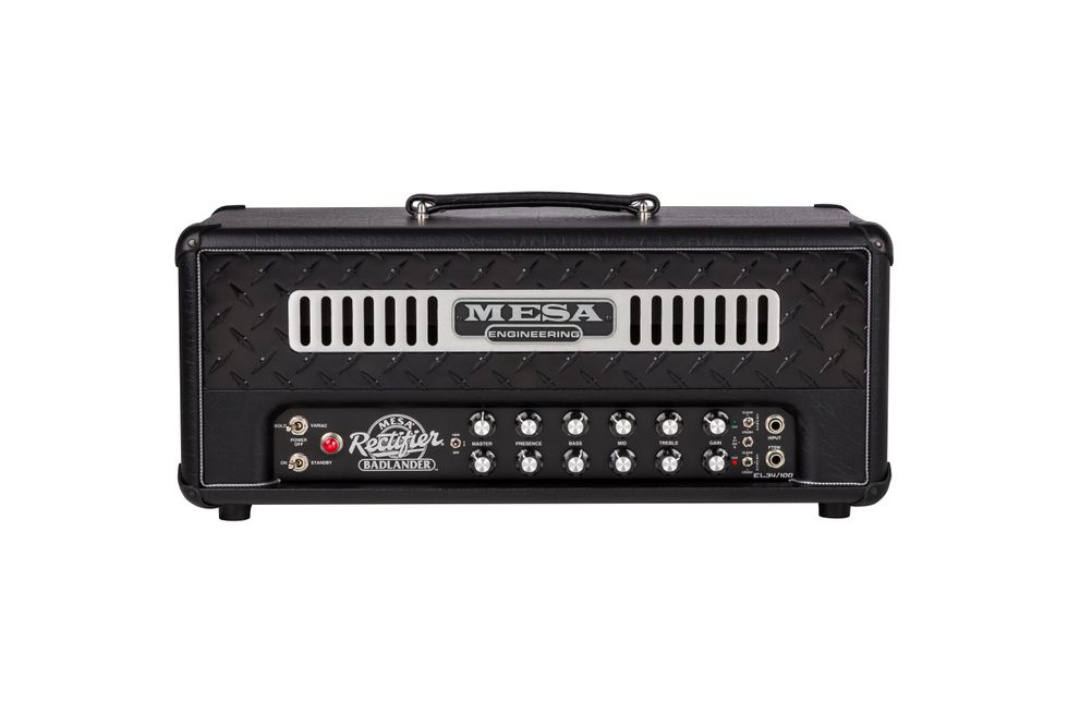
<p>Delivering a sonic and weight profile that’s a bit more lean, the Badlander™ 50 holds its own while adding a distinct tonal character to the Badlander Series. Even more aggressive, yet with an inviting, effortless feel, it’s ready to go places where less power is the call. Two channels feature 3 new dynamic Modes as its 100-Watt counterpart. CLEAN, CRUNCH and CRUSH repeated supply the gain, shaping power and an urgent personality to navigate any venue. Here in the Badlander 50, the 2-Channel preamp hooks up with two different and perfect power displacements that enhance everything from clean to clipped to wildly saturated. The 50-Watt setting delivers bold authority and the highest headroom while the 20-watt setting finds the power tubes re-wired for Triode operation that unveils greater clipping potential and a mid-scooped, harmonic-laden response that reveals trademark EL34 Tone.</p>
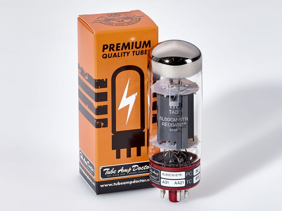
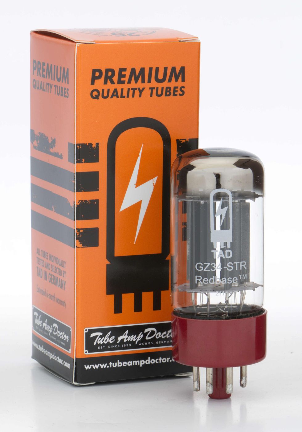
<p>As the first tube of the new TAD REDBASE™ series, the TAD 6L6GCM-STR REDBASE™ has a powerful but always well-defined bass range, with clear, silky and transparent highs - offering plenty of headroom.<br/><br/>In every setting, the TAD 6L6GCM-STR REDBASE™ responds directly and with great dynamics, from soft and warm to punchy and powerful, without ever losing detail or depth.<br/><br/>An effective upgrade<br/><br/>The TAD 6L6GCM-STR REDBASE™ is the recommendation for lively clean sounds as well as powerful broadband multi-channel amps. This makes the TAD 6L6GCM-STR REDBASE™ an effective upgrade for virtually any amp that uses 6L6GC or 5881 tubes.</p>
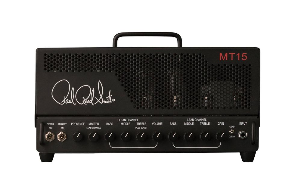
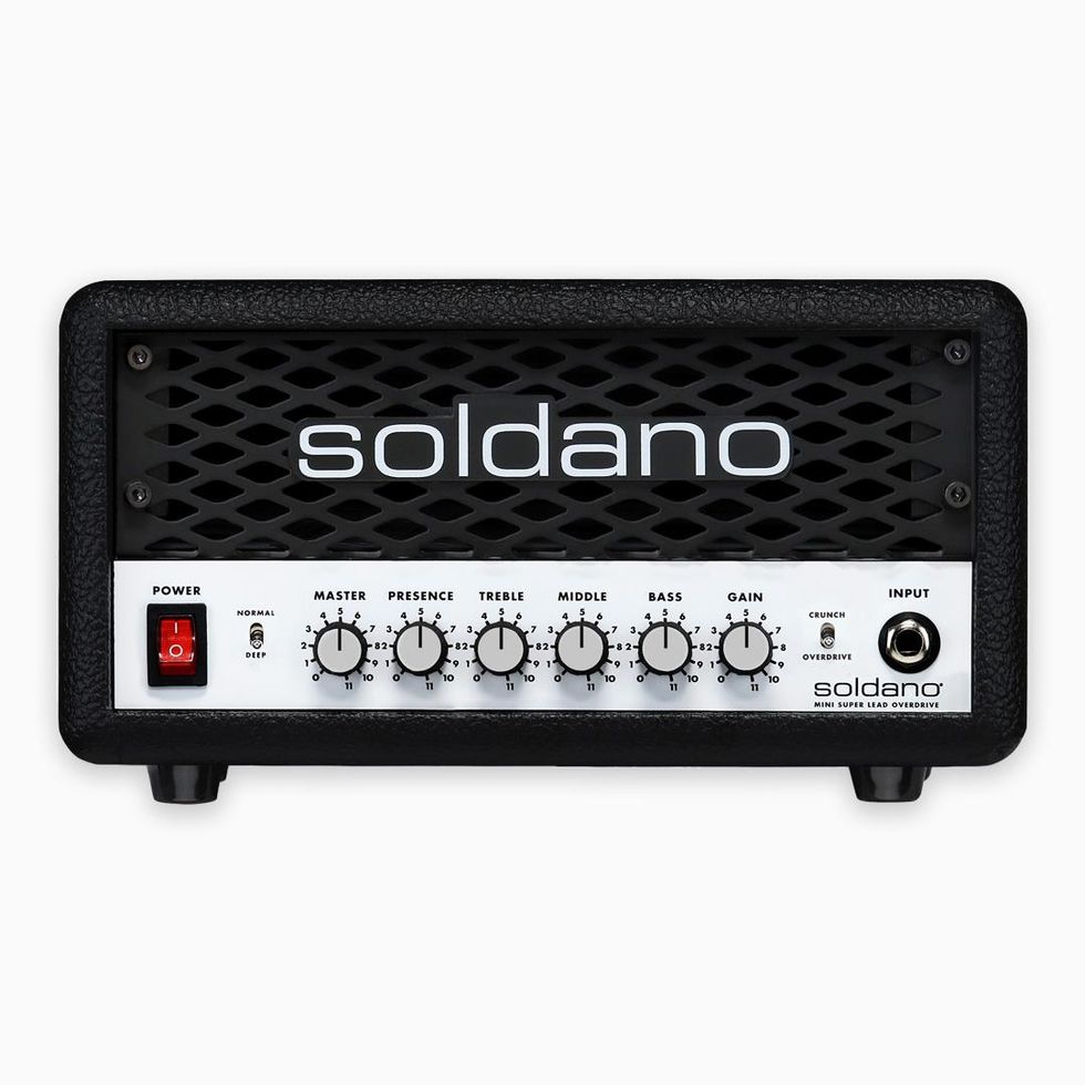
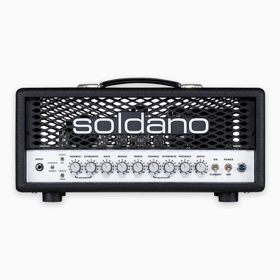
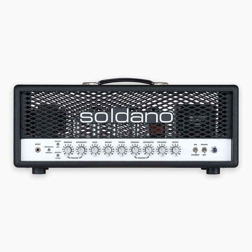
<p>The SLO Mini head is a 30-watt powerhouse with the same rich overdrive and crunch as the original amplifier. This ultra-compact head delivers searing harmonics, and the perfect balance of gain, sustain and tight touch response that the SLO has become famous for.</p>
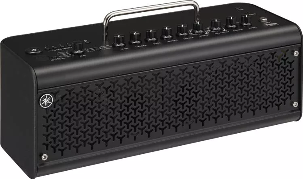
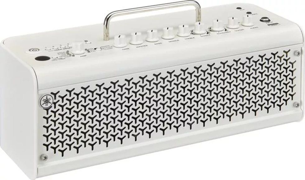
<p>No matter where you are, you can plug into a Yamaha THR30 II Wireless and experience realistic tube tone. This battery-powered combo amplifier includes a full arsenal of guitar and bass amp emulations, along with mic models for your acoustic-electric and flat modes for everything else. Ditch your pedalboard — the THR30 II Wireless’s 3-band EQ, and a great-sounding selection of modulation effects, echoes, and reverbs, have you covered. Bluetooth support enables you to stream backing tracks — with full Hi-Fi quality — through the THR30 II Wireless’s stereo speakers. The THR30 II Wireless also includes plug-and-play USB connectivity for recording and playback, along with a built-in wireless receiver for performing cable-free.</p>
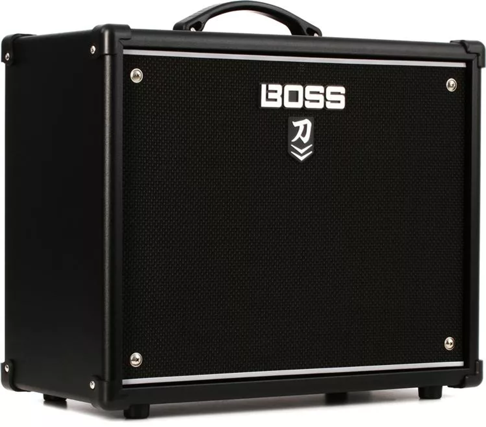
<p>The <a href="https://www.premierguitar.com/tag/boss?utm_source=website&utm_medium=link&utm_campaign=Smartlinks">BOSS</a> Katana-50 MkII is the latest installation in BOSS's esteemed line of Katana series amplifiers. And whether you're interested in accessing its pummeling 50-watt output section and platform-perfect 12-inch speaker to amplify your existing modelers and preamps, or in building your dream tones from the ground up to create the ultimate all-in-one gig and practice solution, take it from Sweetwater — the Katana-50 MkII is a powerful tool in the hands of any electric or acoustic player. Cab-emulated outputs and monitoring make the BOSS Katana-50 MkII a truly silent stage and studio guitar solution, while multichannel footswitch support provides hands-free remote access to every sound in your arsenal. New amp variations and access to 60 timeless BOSS effects within the BOSS Tone Studio editor make the 50 MkII a tone tweaker's holiday.</p>
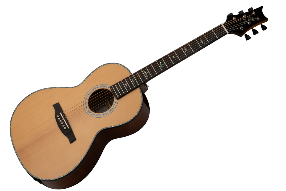
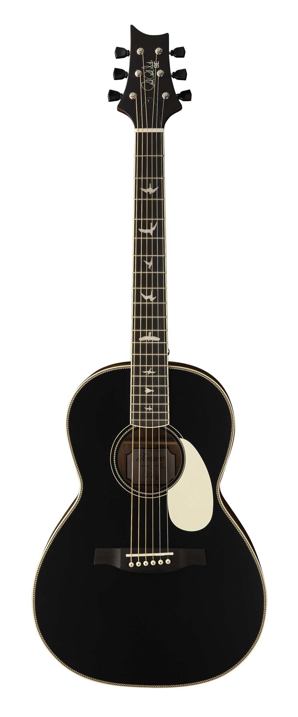
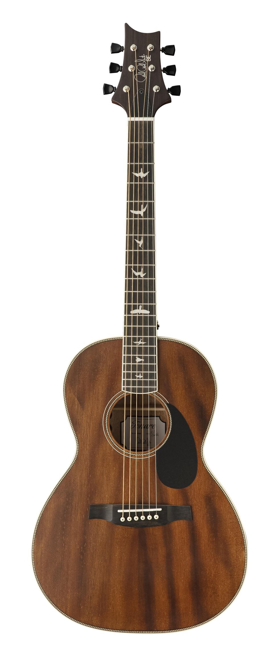
<p>The <a href="https://www.premierguitar.com/tag/prs?utm_source=website&utm_medium=link&utm_campaign=Smartlinks">PRS</a> SE P20 is a parlor-sized acoustic with a<br/>big voice. Boasting traditional parlor features<br/>like sweet, midrange tone, historic vibe, and easy<br/>portability, the PRS SE P20 also brings a unique<br/>voice to players. The PRS hybrid “X”/Classical<br/>bracing locks down the back and sides while<br/>allowing the top to freely vibrate, allowing the<br/>PRS SE P20 to project with even, bold tone, while<br/>the all-mahogany construction provides an organic<br/>warmth to the guitar. Its smaller size keeps<br/>playing fun and comfortable for hours, so whether<br/>writing, recording, or performing the P20 is sure<br/>to impress.<br/><br/>Available in three satin finishes with herringbone<br/>rosettes and accents, PRS SE Parlor acoustics look<br/>as good as they sound. Other high-quality features<br/>include a solid mahogany top, ebony fretboard and<br/>bridge, bone nut and saddle, as well as PRS<br/>trademark bird inlays and headstock design.</p>
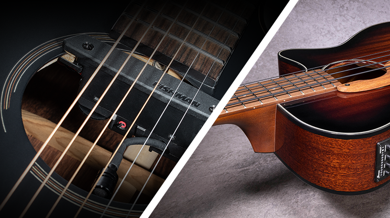
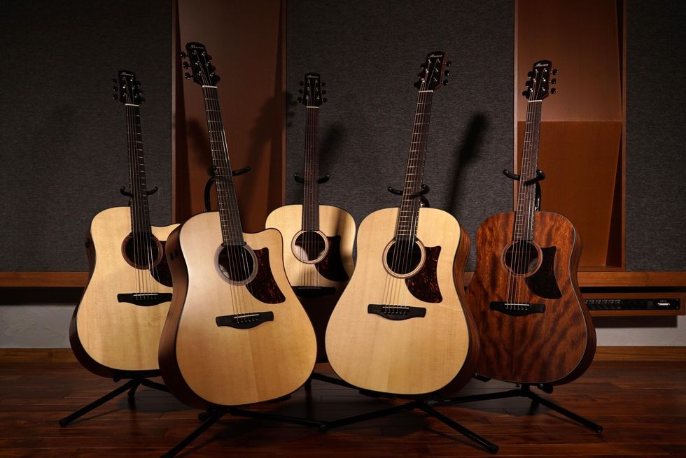
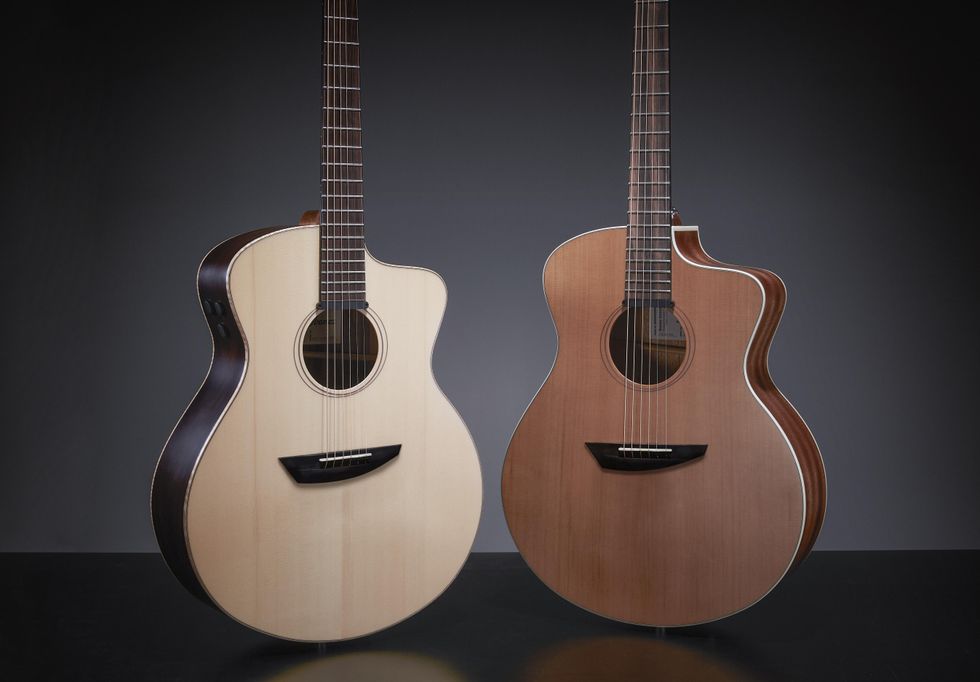
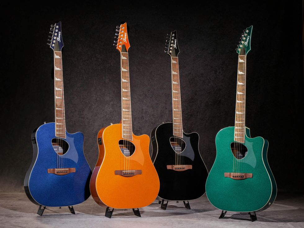
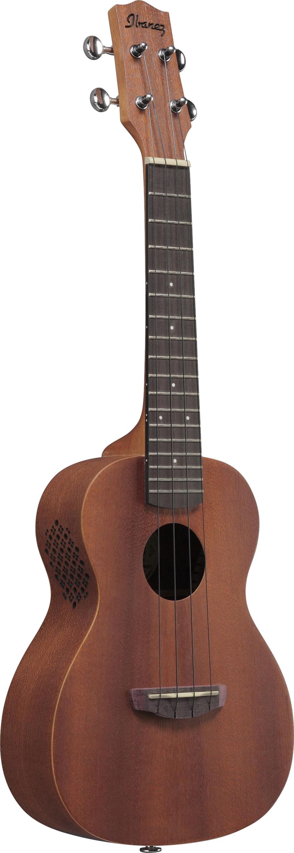
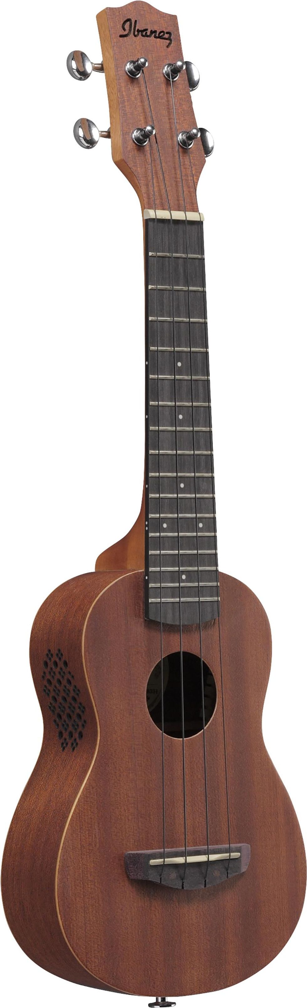
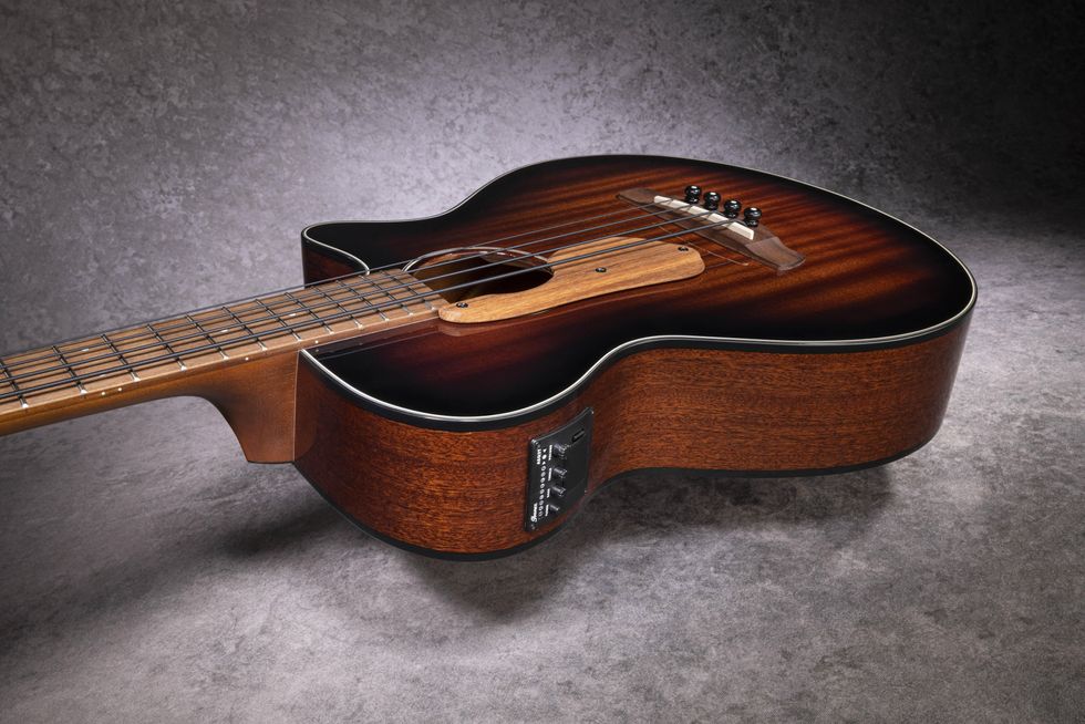
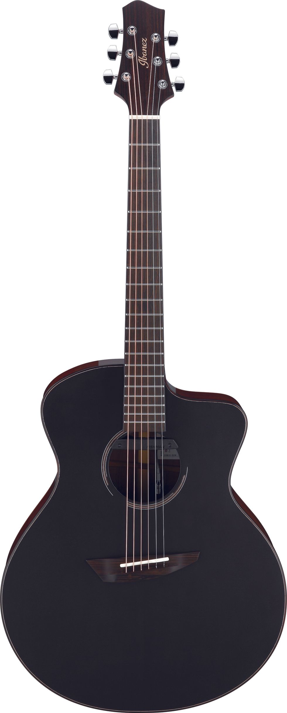
<p>The Advanced Acoustic series represents an important step forward in the long and storied tradition of the acoustic guitar. In what amounts to a fully reimagined acoustic experience, these instruments were designed from the ground up to deliver a richer, brighter, and louder tone, with an unprecedentedly wide dynamic range. With slightly larger than typical proportions, Ibanez decided to name this new body shape the “Grand Dreadnought.” This reinvented design achieves a superb, powerful sound, and thanks to the extensive consideration given to the ergonomics, it’s extremely comfortable to play. The Advanced Acoustic series pushes the acoustic guitar to new heights in a way that promises an exciting experience for all players.</p>
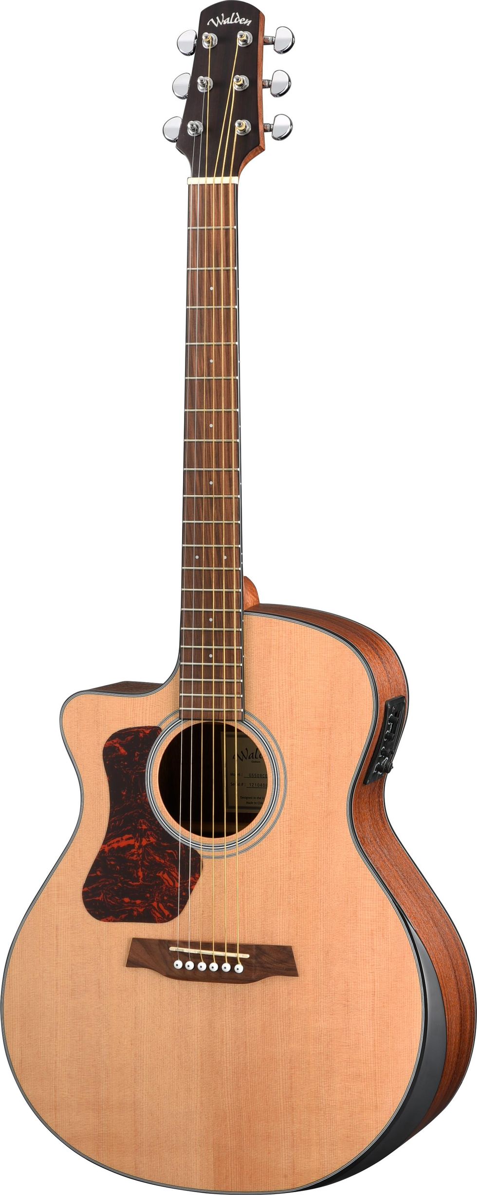
Left-Handed Guitarists: mid-priced acoustic-electric with an Ergonomic Armrest seeking partner to make beautiful music.
“Wow, the armrest really helps keep from cutting off blood circulation when I’m practicing and feels like I’m playing a smaller instrument. Responds nicely both to some intimate playing, and has nice character when you hit it a little hard; it responds with a good full low end and is still crisp and clear.” ~ Sean Harkness, NYC
The NATURA G550RCEL is a Left-handed acoustic-electric featuring an Ergonomic Armrest for comfort. The G550RCEL is a solid Spruce top Grand Auditorium Cutaway with weight reducing Low-Mass bracing. It has a voice that is focused and harmonically complex and suitable for left-handed players looking for the volume of a full-sized instrument and the comfort of a smaller body. A Glass-fibre reinforced neck ensures a lifetime of neck stability.
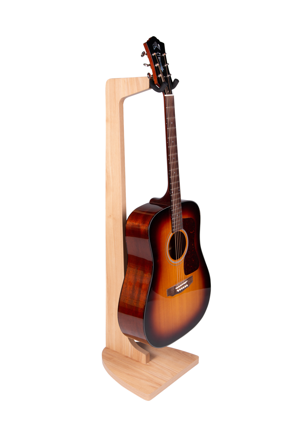
We love metal at Gator – both the head-banging and physical types. While our metal stands are great for the stage and studio, they don’t always blend into their environment. Sometimes you need something more elegant and adaptable to the overall vibe of
your living room or studio furniture, which is exactly what the Elite Guitar Hanging Stands by Gator Frameworks provide – simplicity with an aesthetic to match any home or studio décor. These stands satisfy all types of players by providing a comfortable fit for most electric, bass and acoustic guitars. Show off your collection with style!
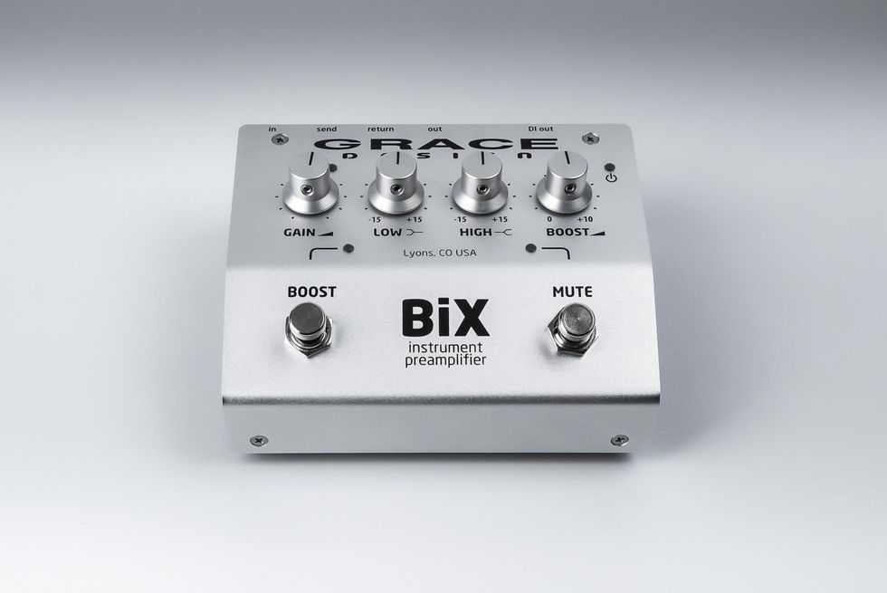
The Grace Design BiX preamp shares the exact same DNA of its bigger siblings, FELiX2 and ALiX, but with an intelligently streamlined feature set and a price that puts it in reach of any performer, whether on your way to the coffee shop or the Megadome. BiX delivers maximum clarity and detail for any plugged in instrument, with dead simple controls – input gain, high and low shelving EQ, and a 10dB variable boost circuit, with footswitches for mute and boost. I/O includes instrument input, separate send and return insert jacks, an unbalanced line output, and a balanced ISO DI output on XLR. And BiX is pedalboard friendly, with a 9VDC power input and a compact, rugged low-profile chassis. Visit www.gracedesign.com for complete details.
This Premier Guitar Web Site (the "Web Site") is provided to you by Gearhead Communications, LLC ("Gearhead Communications"). Access to and use of the Web Site and the services available on the Web Site are subject to the following terms and conditions in this Terms of Use and Privacy Policy. By accessing or using the Web Site, you agree to be legally bound by the terms and conditions set forth below without any modification. Please review them carefully.
The copyright on this entire Web Site is held by Gearhead Communications. All material provided on the Web Site is protected under United States copyright laws and international copyright laws and treaty provisions. Except as expressly provided herein, none of the material provided on the Web Site may be copied, distributed, republished, reproduced, downloaded, displayed or transmitted in any form for commercial use without prior written permission of Gearhead Communications. Individual visitors of the Web Site are permitted personal, non-commercial use, provided that they do not modify the materials on the Web Site and that the materials retain all copyright and other proprietary notices contained therein. The permission terminates automatically if you breach any of the terms and conditions contained in this notice. Gearhead Communications does not grant any express or implied right to you under any patents, trademarks, copyrights, or trade secret laws.
The trademarks, logos, and service marks (collectively referred to as "Trademarks") displayed on this Web Site are federally registered and unregistered Trademarks of Gearhead Communications and no trademark license either express or implied is granted by Gearhead Communications. You do not have any right to use the Trademarks displayed on this Web Site without prior written permission of Gearhead Communications. In the event of unauthorized use or misuse of its Trademarks, Gearhead Communications will pursue its legal remedies without delay.
ELECTRONIC INFORMATION SUBMITTED TO THE WEB SITE Any communication or material other than your personal information submitted to the Web Site by electronic mail is the exclusive property of Gearhead Communications and is considered to be non-confidential and non-proprietary. Such communication may include, without limitation, questions, comments, suggestions, and ideas. Gearhead Communications shall be free to use them for any purpose whatsoever without restriction or compensation.
DMCA NOTICE Gearhead Communications respects the intellectual property of others, and we ask our content partners and those posting to this Web Site to do the same. If you believe that your copyrighted work has been copied and is accessible on this Web Site in a way that constitutes copyright infringement, you may notify us by providing our copyright agent with sufficient information to allow us to locate the material, including the following information:
The electronic or physical signature of the owner of the copyright or the person authorized to act on the owner's behalf.
A description of the copyrighted work that you claim has been infringed and a description of the infringing activity.
Identification of the location where the original or an authorized copy of the copyrighted work exists; for example, the URL of the web site where it is posted or the name of the book in which it has been published.
Identification of the URL or other specific location on this web site where the material that you claim is infringing is located.
Your name, address, telephone number, and email address.
A statement by you that you have a good faith belief that the disputed use is not authorized by the copyright owner, its agent, or the law.
A statement by you, that the above information you provide us is accurate and that you are the copyright owner or are authorized to act on the behalf of the copyright owner.
Our agent for notice of claims of copyright infringement on this Web Site can be reached as follows:
By Mail: Gearhead Communications, LLC
Patti Erenberger
3 Research Center
Marion, IA 52302
By Phone: (319) 447-5550 By Fax: (319) 447-5599 By Email: patti [at] premierguitar.com
DISCLAIMER THE INFORMATION IN THIS WEB SITE IS PROVIDED "AS IS" WITHOUT WARRANTY OF ANY KIND, EITHER EXPRESS OR IMPLIED, INCLUDING BUT NOT LIMITED TO, THE IMPLIED WARRANTY OF MERCHANTABILITY, FITNESS FOR A PARTICULAR PURPOSE AND NON-INFRINGEMENT. GEARHEAD COMMUNICATIONS SHALL NOT BE RESPONSIBLE FOR ANY ERRORS, OMISSIONS, OR TECHNICAL INACCURACIES IN THIS WEB SITE.
Gearhead Communications is constantly improving its products and services and reserves the right to make such improvements or changes to this Web Site, the materials, products, services, or prices posted on this Web Site without prior notice, as it deems necessary.
PRIVACY Gearhead Communications is committed to protecting your privacy. Gearhead Communications and its affiliates collect personal information from its users in limited situations as set forth in this Terms of Use and Privacy Policy. Unless otherwise indicated, Gearhead Communications and its affiliates will only disclose personally identifiable information to third parties when required by law or in the good faith belief that such action is necessary in order to conform to the edicts of the law or comply with the legal process served on this Web Site. Unless otherwise stated in this Terms of Use and Privacy Policy, Gearhead Communications and its affiliates will not rent, sell or give your personally identifiable information to any outside party without your prior permission. Gearhead Communications and its affiliates may now or in the future use personally identifiable information, such as email addresses submitted by users, to contact users and third parties and provide information on internal promotions of Premier Guitar and its affiliates. If and when this feature becomes available, users will be given the option to opt out of receiving such promotions.
You are responsible for taking all reasonable steps to ensure that no unauthorized person shall have access to your Web Site password or account. You are solely responsible for:
Controlling dissemination and use of your user name, member ID and/or password;
Authorizing, monitoring and controlling access to and use of your Web Site user name, member ID or password; and
Promptly informing Gearhead Communications of any need to deactivate a password.
You grant Gearhead Communications and its affiliates the right to transmit, monitor, retrieve, store and use your information in connection with the operation of the Web Site. Gearhead Communications and its affiliates cannot and do not assume any responsibility or liability for any information you submit for your or any third party's use or misuse of the information transmitted or received using their web site.
PUBLIC AREAS The Web Site may now or in the future provide users opportunities to comment on articles posted on the Web Site and to access public areas including chat rooms, bulletin boards or other online communities. By posting comments or using any public area on the Web Site, you agree that you are solely responsible for your own communications, the consequences of posting such communications, and your reliance on any such communications found in the public areas. Gearhead Communications assumes no responsibility for the consequences of any communications in the public areas.
By using the public areas, you agree that the following actions constitute a material breach of this Terms of Use and Privacy Policy:
Using a public area for any purpose in violation of local, state, national or international law;
Posting any material in a public area that infringes the intellectual property rights of others or the privacy or publicity rights of others;
Posting any material that is unlawful, obscene, defamatory, threatening, harassing, abusive, slanderous, hateful or embarrassing to any other person or entity as determined by Gearhead Communications in its sole discretion;
Posting advertisements or solicitations of business;
Upon receiving a warning, continuing to disrupt the normal flow of dialogue or posting comments that are not related to the topic being discussed;
Posting chain letters or pyramid schemes;
Impersonating another person;
Distributing viruses or other harmful computer code;
Harvesting or otherwise collecting information about others, including e-mail addresses, without their identification for posting or viewing comments;
Allowing any other person or entity to use your identification for posting or viewing comments;
Posting the same note more than once or "spamming"; or
Engaging in any other conduct that restricts or inhibits any other person from using or enjoying the public areas or the Web Site, or which in the judgment of Gearhead Communications exposes Gearhead Communications, its affiliates or licensors to any liability or detriment of any type.
Gearhead Communications reserves the right to record the dialogue in any public areas. Gearhead Communications does not screen communications in advance and is not responsible for screening or monitoring material posted by any user. If notified by a user of communications which are alleged not to conform to this Terms of Use and Privacy Policy, Gearhead Communications may investigate the allegation and determine in its sole discretion to remove or request the removal of communications. Gearhead Communications reserves the right to remove communications which are abusive, illegal, disruptive or that otherwise fail to conform to this Terms of Use and Privacy Policy. In addition to the removal rights described above, Gearhead Communications reserves the right to terminate any user access to any or all public areas upon user's breach of this Terms of Use and Privacy Policy. Gearhead Communications reserves the right (but is not obligated) to edit or delete any communications posted on any public area, regardless of whether such communications violate these standards for conduct.
Gearhead Communications reserves the right to take any action it deems necessary to protect the personal safety of its users or the public. Gearhead Communications has no liability or responsibility to users of the Web Site or any other person or entity for performance or non-performance of the aforementioned activities.
CHILDREN'S PRIVACY We are committed to protecting the privacy of children. You should be aware that the Web Site is not intended or designed to attract children under the age of thirteen (13). We do not collect personally identifiable information from any person we actually know is a child under the age of thirteen (13).
INFORMATION SUBMITTED BY USER You agree that you will not upload or transmit any type of communication or content to any public area that infringes or violates any rights of any party. By submitting any communication or content, including any business information, ideas, concepts or inventions to Gearhead Communications by e-mail or any other manner, you agree that such submission is non-confidential for all purposes. By submitting any such information to a public area or via e-mail, you automatically grant, or warrant that the owner of such content or intellectual property has expressly granted to Gearhead Communications and its affiliates a royalty-free, perpetual, irrevocable, worldwide, non-exclusive license to use, reproduce, create derivative works from, modify, publish, edit, translate, distribute, perform and display the communication or content in any media or medium or any form, format or forum now known or hereafter developed. If you wish to keep any business information, ideas, concepts or inventions private or proprietary, do not submit them to the public areas or to Gearhead Communications by e-mail.
LINKS Gearhead Communications may provide links to third party web sites. Gearhead Communications and its affiliates do not recommend and do not endorse the content on any third party web site and are not responsible for the content of linked third party sites, sites framed within the Web Site, third party sites provided as search results, or third party advertisements, and does not make any representations regarding their content or accuracy. Your use of third party web sites is at your own risk and subject to the terms and conditions of use for such sites.
COOKIES/LOG FILES Cookies are files that contain information created by a web server that can be stored on a user's hard disk for use either during a particular session or for future use. Gearhead Communications uses cookies for maintaining user account information, to help administer the Web Site, to measure the use of the Web Site and to improve the content of the Web Site. Users may set their computers to refuse cookies. Most browsers are initially set to accept cookies.
The Web Site may also use cookies and/or log files to collect information such as date and time of use, users' IP address and links and pages viewed by users of the Web Site. Such information is gathered for the purposes of maintaining user account information and is not used to disseminate significant information about users over the Internet or to analyze any information that users have knowingly or unknowingly provided. Such information will be accessible only by Gearhead Communications and its internet Web Site service provider.
INDEMNITY You agree to defend, indemnify and hold Gearhead Communications and its affiliates and their respective officers, members, employees, agents, licensors and suppliers harmless from and against any claims, actions or demands, liabilities and settlements, including, without limitation, reasonable legal and accounting fees resulting from or alleged to result from your violation of this Terms of Use and Privacy Policy.
GENERAL Gearhead Communications, LLC is an Iowa limited liability company. Gearhead Communications makes no claims that the content provided in the Web Site is appropriate or may be downloaded outside of the United States. Access to the content in the Web Site may not be legal by certain persons or in certain countries. If you access the Web Site from outside the United States, you do so at your own risk and are responsible for compliance with the laws of your jurisdiction.
In the event all or a portion of the assets owned or controlled by Gearhead Communications or any parent, subsidiary or affiliated entity are sold, assigned, transferred or acquired by another company, information from or about Web Site users may be among the transferred assets.
JURISDICTION You expressly agree that the exclusive jurisdiction for any dispute with Gearhead Communications, or in any way relating to your use of the Web Site, resides in the courts of the State of Iowa and you further agree and expressly consent to the exercise of personal jurisdiction in the courts of the State of Iowa in connection with any such dispute, including any claim involving Gearhead Communications or its affiliates, subsidiaries, employees, officers, members, telecommunication providers, licensors and suppliers. This Terms of Use and Privacy Policy is governed by the internal substantive laws of the State of Iowa without respect to its conflict of law principles. If any provision of this Terms of Use and Privacy Policy is found to be invalid by any court having competent jurisdiction, the invalidity of such provisions shall not affect the validity of the remaining provisions of this Terms of Use and Privacy Policy, which shall remain in full force and effect. No waiver of the Terms of Use and Privacy Policy shall be deemed a further or continuing waiver of such term or condition or any other term or condition.
COMPLETE AGREEMENT This Terms of Use and Privacy Policy constitutes the entire agreement between you and Gearhead Communications with respect to the use of the Web Site and content.
Thank you for your cooperation. We hope you find the Web Site helpful and convenient. Questions or comments regarding the Web Site should be directed by electronic mail to patti [at] premierguitar.comor via U.S. Mail to Gearhead Communications, LLC, Three Research Center Marion, IA 52302.