Guitar Shop 101 3 Simple Ways to Upgrade Your Strat Replacing key components—such as the pickups, string nut, and tuners—can turn a workhorse guitar into a killer axe!John LeVanApr 15, 2013
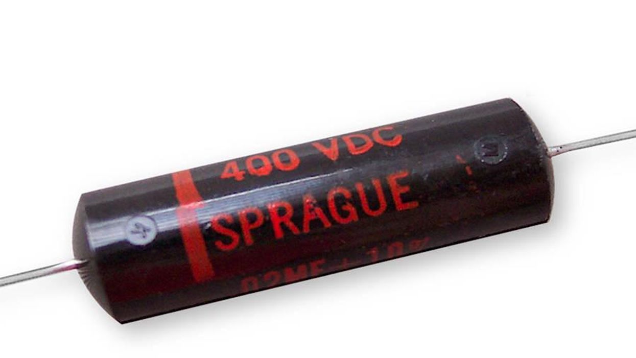
Mod Garage Tone Capacitors for Stratocasters, Part 1 A quick guide to vintage Strat caps - which ones to try, and what you should expect.PremierGuitar DefaultMar 11, 2010
Mod Garage Auditioning Tone Capacitors, Part II We conclude our tone cap journey with a guide to the most common types.Dirk WackerMar 10, 2008
Mod Garage Auditioning Tone Capacitors Breaking the myths of tone capacitors and helping you find the best one for your tone.Dirk WackerJan 29, 2008