Search
Latest Stories
Start your day right!
Get latest updates and insights delivered to your inbox.

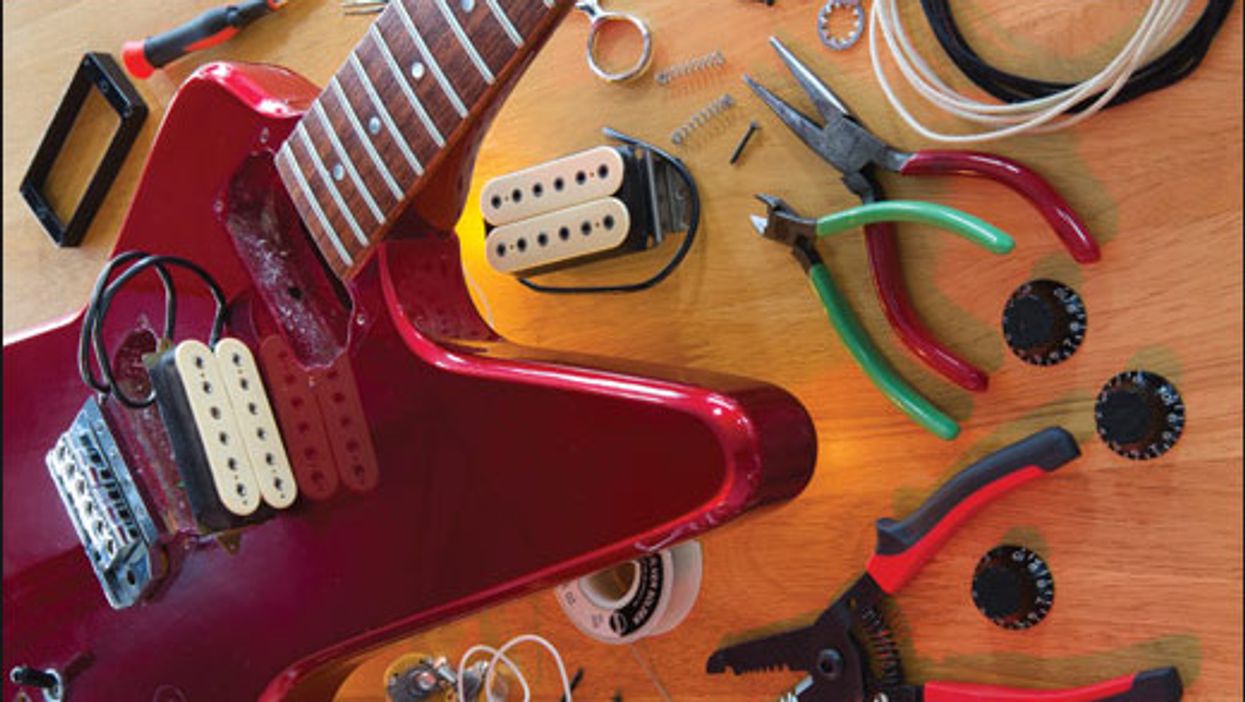
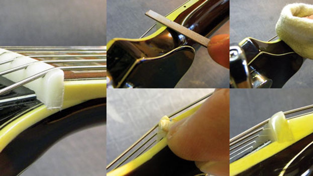
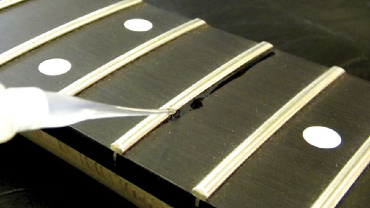
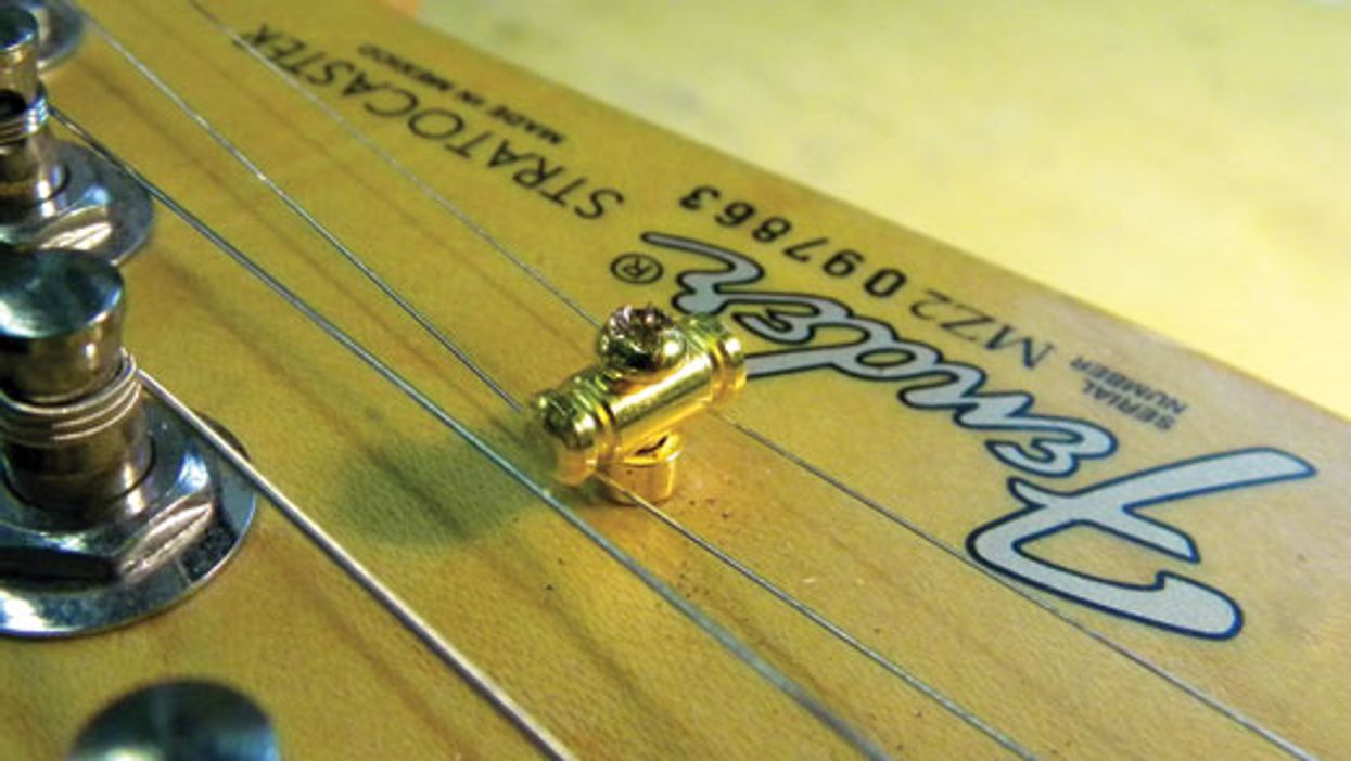
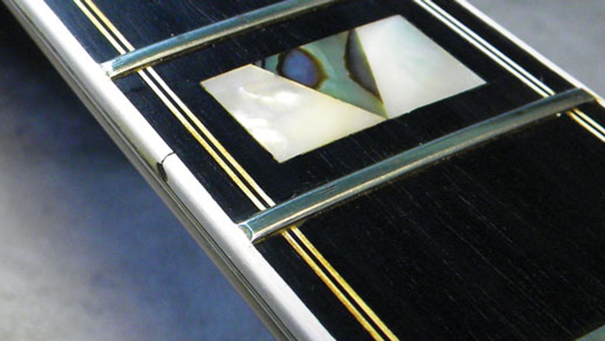
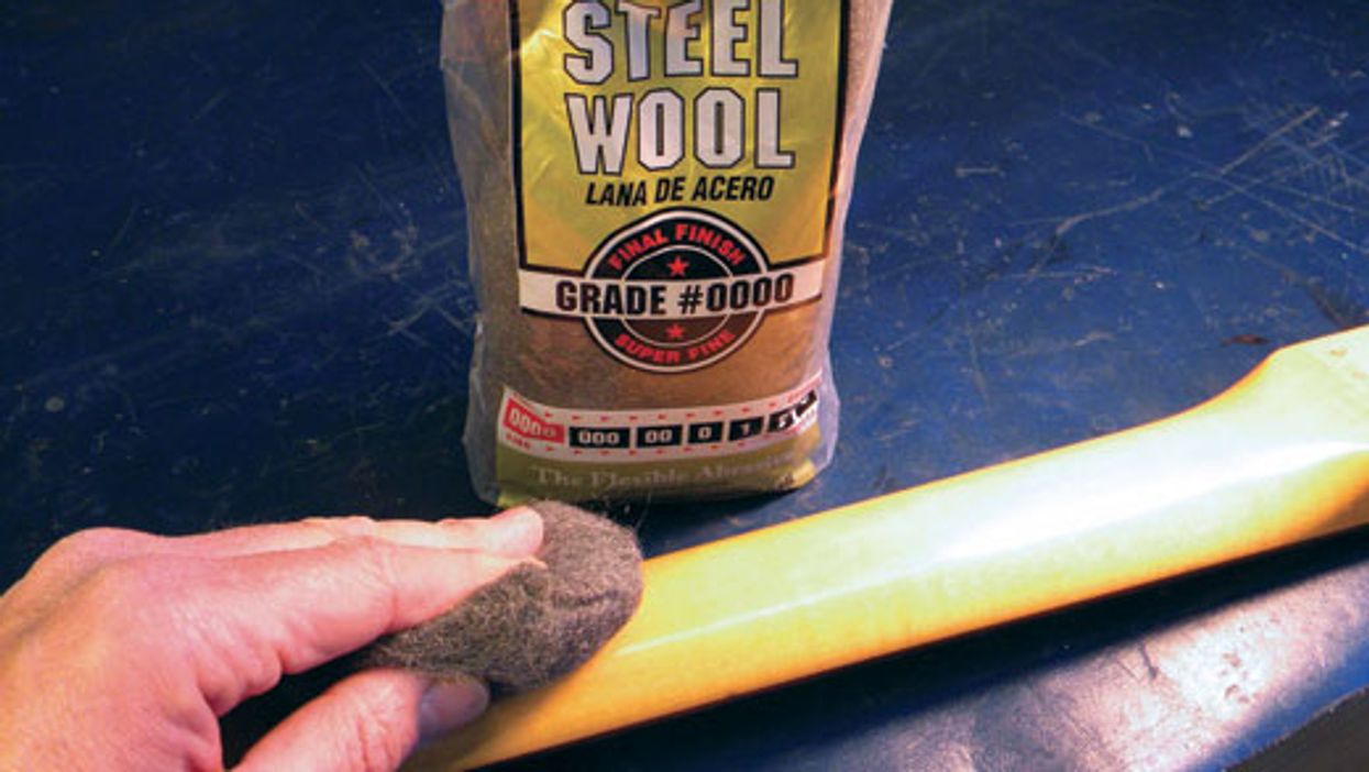
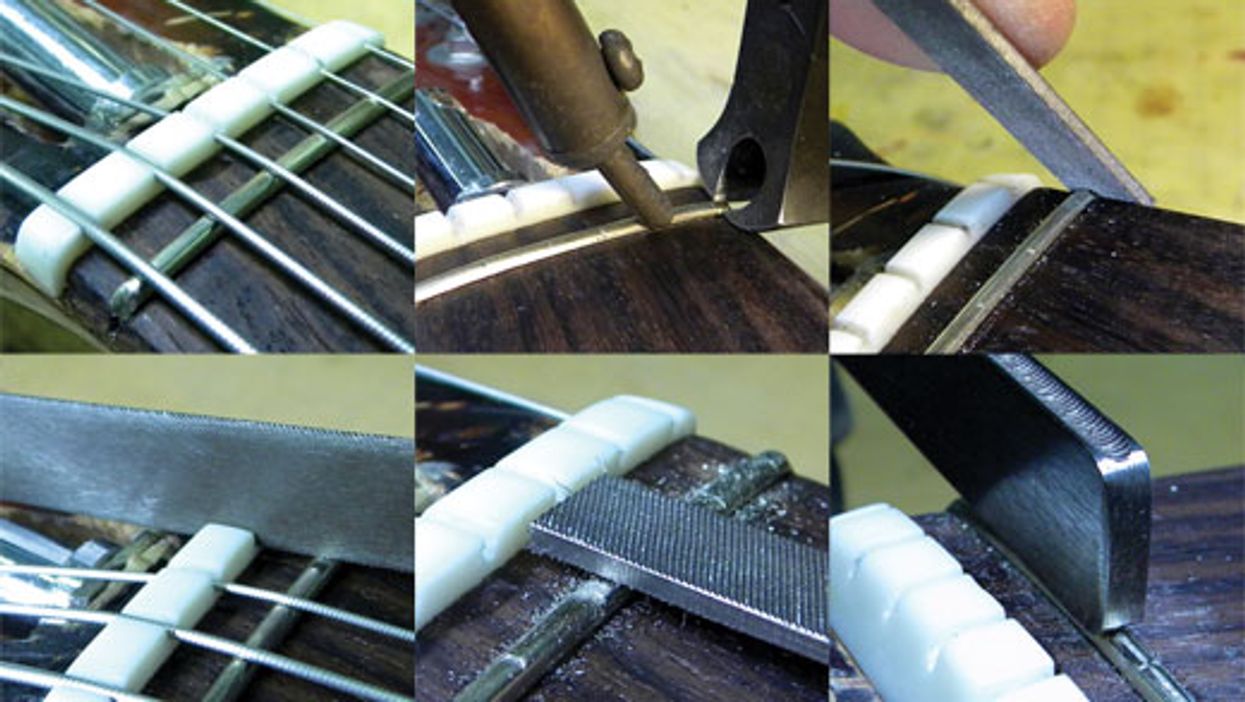
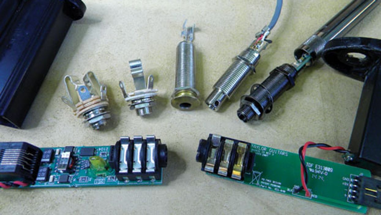
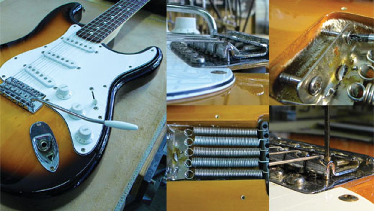
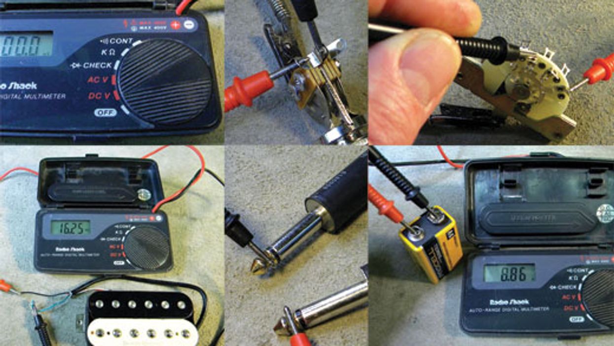
Guitar Shop 101
Dedicated guitarists need to know how to maintain their prized instruments. Nashville guitar tech John LeVan shares all his tips and techniques in this photo-rich blog, and if you wonder what it takes to keep your guitar in gig-worthy condition, Guitar Shop 101 provides the answers. If there’s a topic you’d like to see addressed, drop LeVan an email at guitarservices@aol.com.

Don’t Miss Out
Get the latest updates and insights delivered to your inbox.
Popular
Recent
load more