
Hello and welcome back to Mod Garage. After exploring the half out-of-phase pickup option several times in the past, there was a lot of interest, and I received a lot of emails from readers about it. A lot of you asked for a multi-phase switch to have all possible options at the ready and today we'll bring it all together. You asked for it, and the Mod Garage delivers!
Let's start with what we'll need to get out-of-phase or half out-of-phase sounds:
- You will need to engage at least two pickups to get such sounds. A single pickup played by itself will always sound the same, no matter if you play it in phase or out of phase (more about this later). The magic starts when you engage two (or more) pickups with one in phase and the other one out of phase or half out of phase.
- In general, you'll need one switch for each pickup you want to put out of phase. This can be only one switch, like on the middle pickup of a Stratocaster, to cover both in-between switching positions (bridge+middle and neck+middle), or three phasing switches, like on Brian May´s "Red Special," with one switch for each of the three pickups.
My design of a multi-phase switch that we'll cover today can be used to expand already existing out-of-phase switches in a guitar or to design a new wiring of your choice, integrating such a switch. With this switch, you'll be able to cover all three possible phasing options: in phase, out of phase, and half out of phase.
The magic starts when you engage two (or more) pickups with one in phase and the other one out of phase or half out of phase.
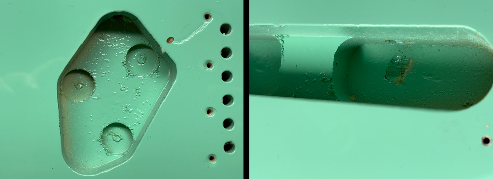
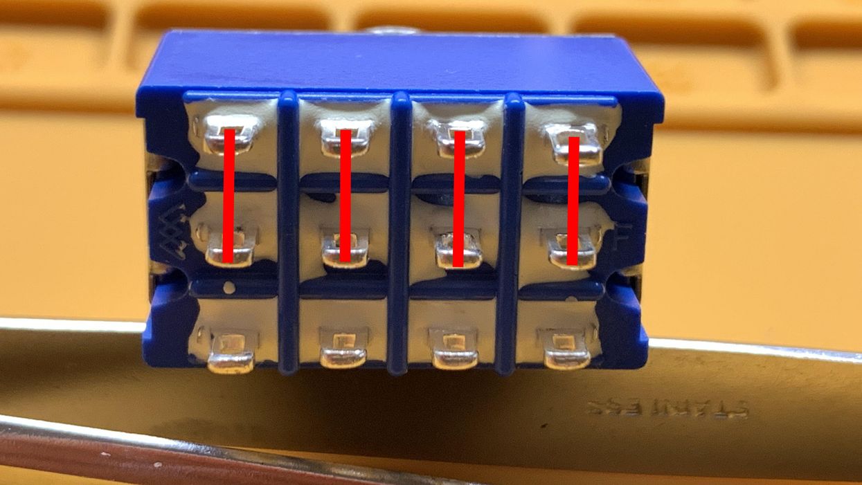
All you need for this mod is the switch, plus a capacitor and a resistor for the half out-of-phase option. So, let's start with the switch itself. For this mod you need a 4PDT on-on-on switch, which means a switch with three switching positions (up-middle-down) and a total of 12 lugs, arranged in four independent sections. Such switches are on the border of being exotic, but they're still available. Since every manufacturer uses a slightly different switching matrix for such switches, you'll need to get one with the same switching matrix I used, which is more or less the quasi-standard for it. It's possible to use 4PDT switches with a different switching matrix, but you'd have to adopt the wiring to it. I've provided three photos of the switching matrix and the switch design for each position. Photo 1 shows the "up" position, which will put the pickups half out-of-phase. Photo 2 shows the "middle" position, which will give you the full out-of-phase option. And Photo 3 shows the "down" position, which is just the normal in-phase operation.
Placing such physically large-sized switches on a pickguard or control plate can be a challenge, so you'll have to be creative. There is no way around such a switch when you want this mod because there are no existing push-pull or push-push pots with on-on-on switches. If you can find a 4P3T rotary switch, you can use it to substitute the switch by replacing one of the pots with it. There are also 4PDT slider switches available, but they're physically about the same size, and therefore, not a real alternative.
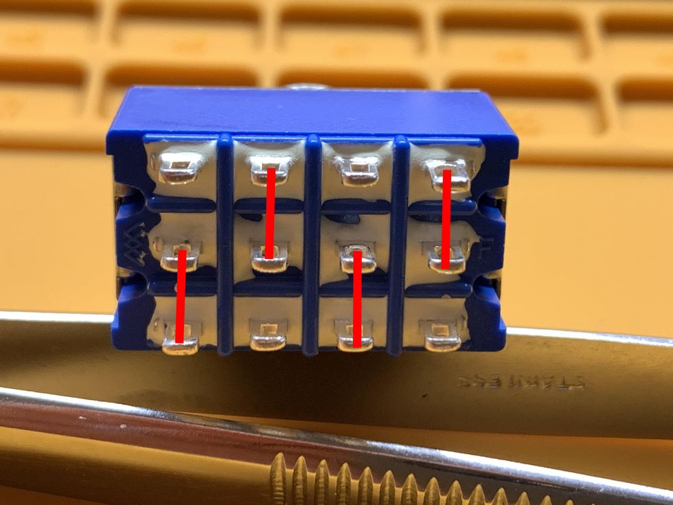
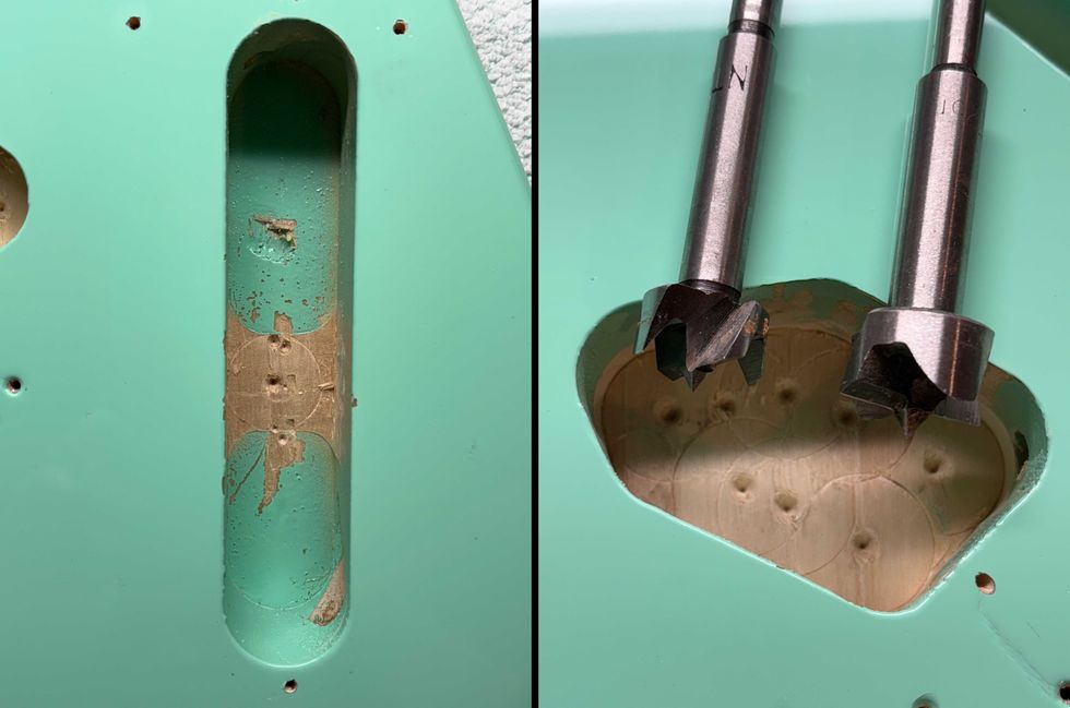
Photo 2 shows the 4PDT switching matrix design for the "middle" position, which will give you the full out-of-phase option.
Image courtesy of singlecoil.com
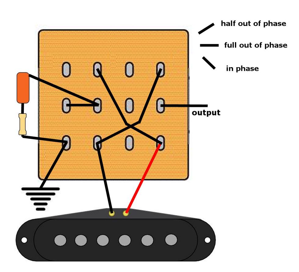
Here we go with the wiring of the switch, shown in Fig. 1. With the lever down you have the normal in-phase operation, with the lever up the pickup is half-out-of-phase, and in the middle position you have the full out-of-phase option.
Anyway, there you have it, all in one switch as shown in Fig. 1. On the left side of the switch, you see a capacitor in series with a resistor for the half out-of-phase option. A good average value is using a 0.01 uF capacitor with a 6.2k-ohm resistor in series as an additional serial attenuation of the system, preventing an impedance peak.
When looking at the switch, you'll notice that one switching stage is not populated at all. You might ask: Why don't we use a 3PDT switch for this if we only need three switching stages? This is because of the asymmetrical switching matrix of the 4PDT switches in the middle position (Photo 2) and there's no way around it. If the on-on-on switch had a completely symmetrical switching matrix, then three switching stages would be enough, but such switches aren't available today.

Photo 3 shows the 4PDT switching matrix design "down" position, which is just a normal in-phase option.
Image courtesy of singlecoil.com
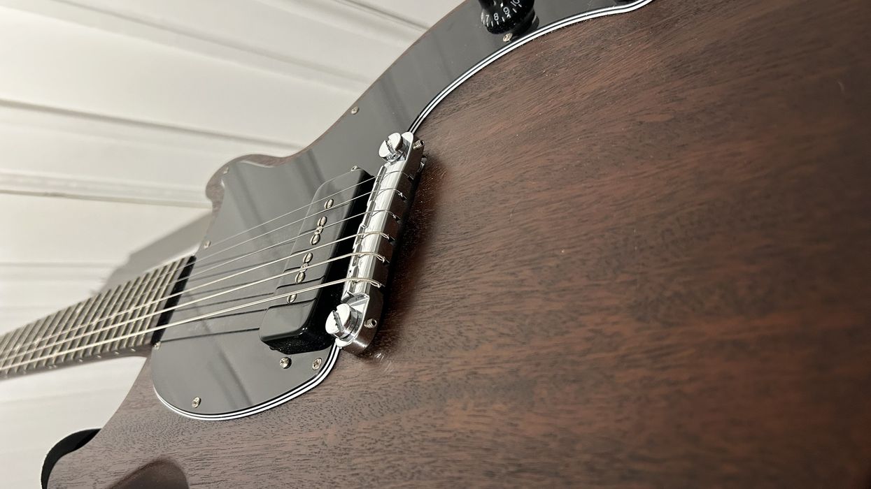
In general, you add a controlled degree of reversed phase of the pickup when using the half out-of-phase option, which is great to mimic Stratocaster in-between "quack tones" on a Telecaster, like on the Jerry Donahue Tele models or with the Bill Lawrence Telecaster wiring.
Phase differences are measured in degrees. Totally in-phase sounds have either 0 or 360 degrees of difference, meaning none. Totally out-of-phase sounds have a 180-degree difference. So, half out of phase is either 90 or 270 degrees of difference. That's the reason why you can only achieve a fully out-of-phase effect when using two pickups together with one wired out-of-phase. (When both pickups are wired out of phase, they sound the same as both pickups in phase, because there are still 0 degrees of phase difference between them.) When a signal passes through a capacitor, the voltage leads the current by 90 degrees, so when a pickup's signal gets routed through a capacitor, it shifts the phase by 90 degrees—exactly half of 180 degrees—and therefore half out-of-phase ... in simple terms.
The cap connected to the switch is the phase-shifting cap mentioned above. A 0.01 uF cap is a great starting point, but you may try caps between 0.005 uF (5000 pF) and 0.022 uF. The smaller the cap, the sweeter the sound will be, but this really depends on your particular pickups. I recommend experimentation and fine-tuning to get as close as possible to a Strat's in-between tones.
As for the attenuation resistor, a 6.2k-ohm resistor works pretty well with the 0.01 uF cap and standard single-coil pickups. As a simple guideline, you can follow this rule by choosing and experimenting with this resistor: The higher the value, the more attenuation in the system, the smaller the impedance peak. A good starting point is the DCR of the pickup that's connected to the switch. For example, if your pickup measures a DCR of 6.8k ohms, you should start with a 6.8k-ohm resistor on the switch for a balanced sound and experiment from there. A good option is to use a small trim pot first so you can experiment until you find the value you like best. You can measure the trim pot and solder a fixed resistor with the measured value on the switch, or simply leave the trim pot where it is. A 10k or 15k trim pot is perfect for this.
That's it for this round. In honor of Fender's 75th Anniversary, next month we'll take a deeper look into Fender's history, busting some myths, misunderstandings, and urban legends, while celebrating the man behind the company that started it all: Mr. Clarence Leonidas Fender, or Leo Fender, as the world calls him.
Until then ... keep on modding!