Question of the Month Question of the Month: What’s Your Favorite Mod? Premier Guitar Staff Mar 22, 2025
Mod Garage The John 5 Ghost Telecaster Wiring This Tele looks flashy, but its unique wiring scheme is simple and easy to recreate. Dirk Wacker Oct 07, 2023
Mod Garage Build Your Own PRS Sweet Switch The parts for the vaunted device may be out of production, but there’s still a way to simulate it on your own guitar. Dirk Wacker Jul 23, 2023
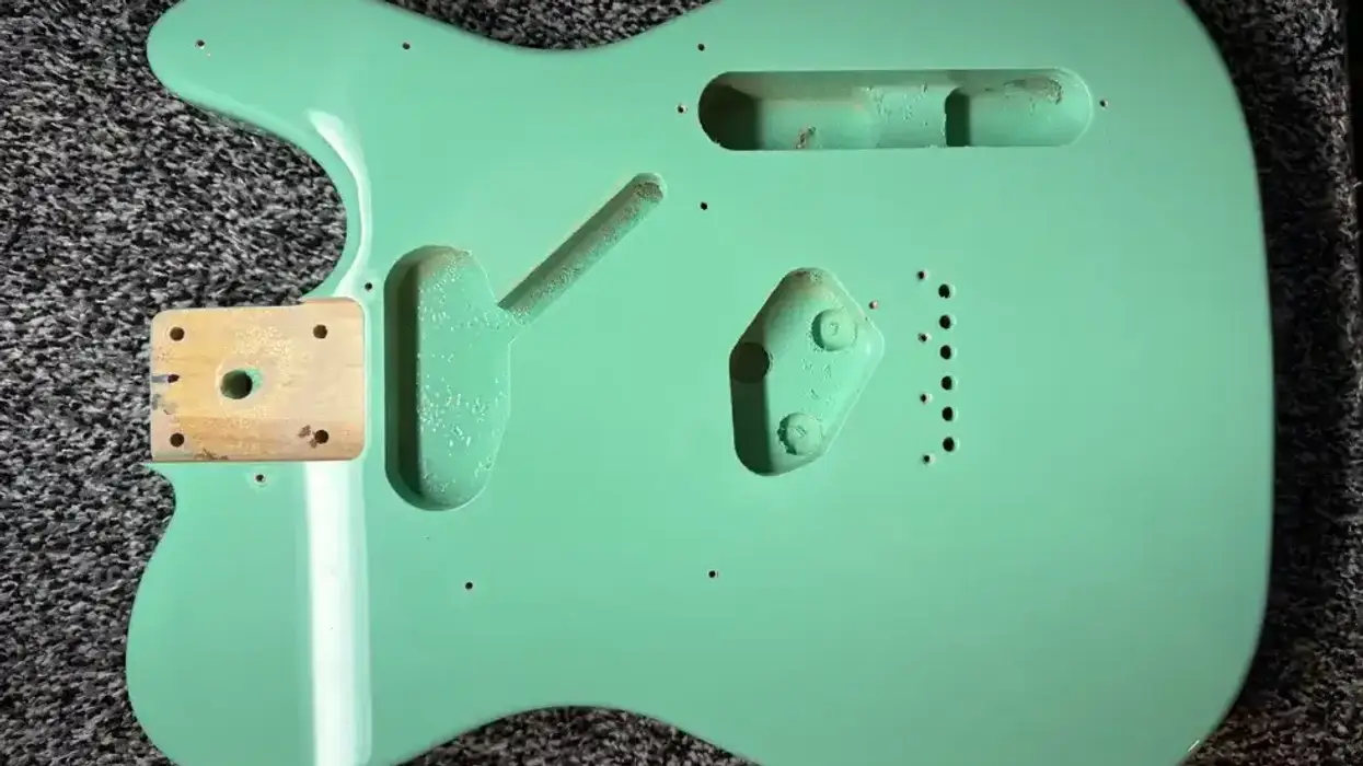
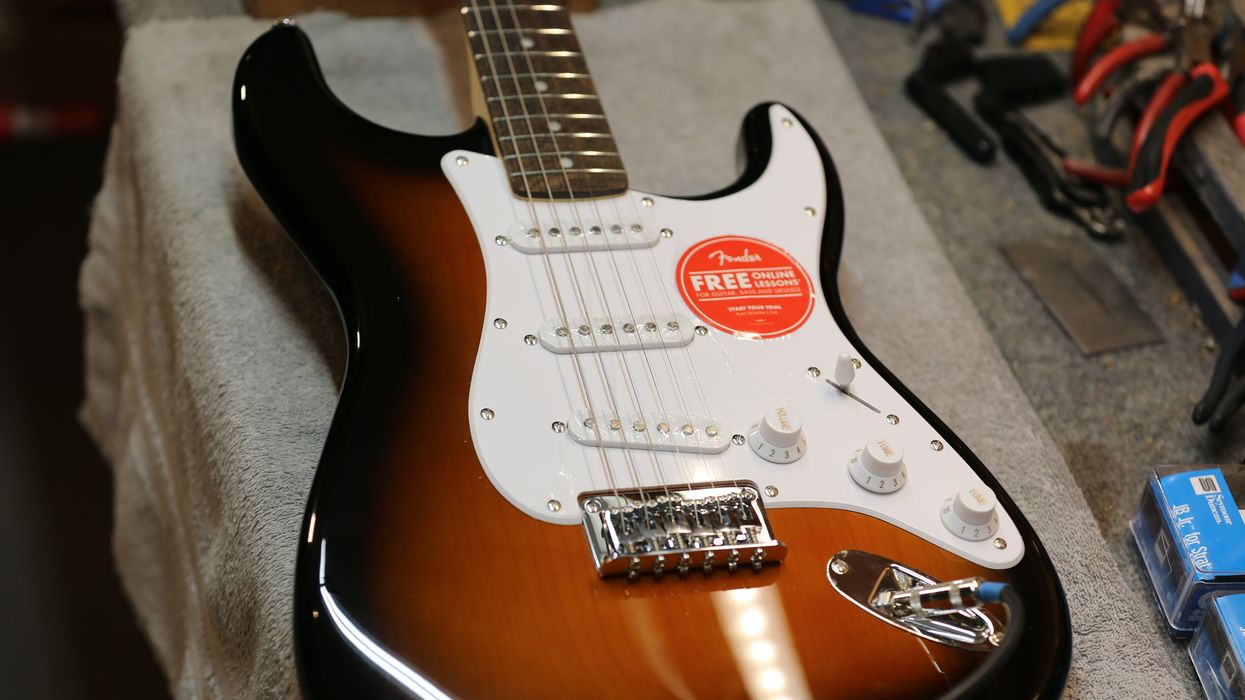
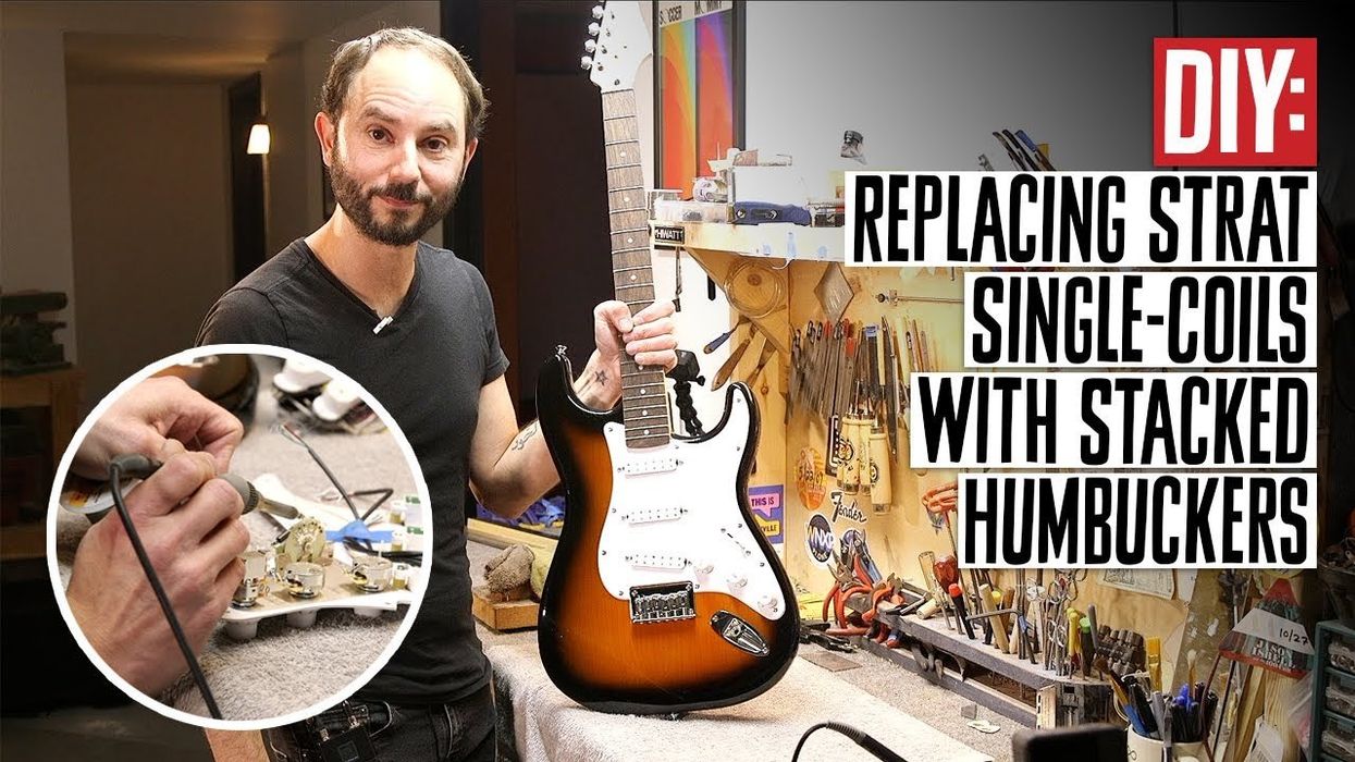
Guitar & Bass Mods DIY: Hot-Rodding a Squier Bullet HT A step-by-step guide to transforming a template single-coil import into a humbucker-equipped firebreather with neck-and-bridge-pickup coil-splitting. Dave Johnson Apr 11, 2023
DIY DIY Guitar: 8 Cool Reader Mods A spotlight on real-life DIY adventures, from a steampunk-inspired work of art to a tone-happy Strat-style to a 1961 Gibson restoration. Premier Guitar Staff Apr 04, 2023
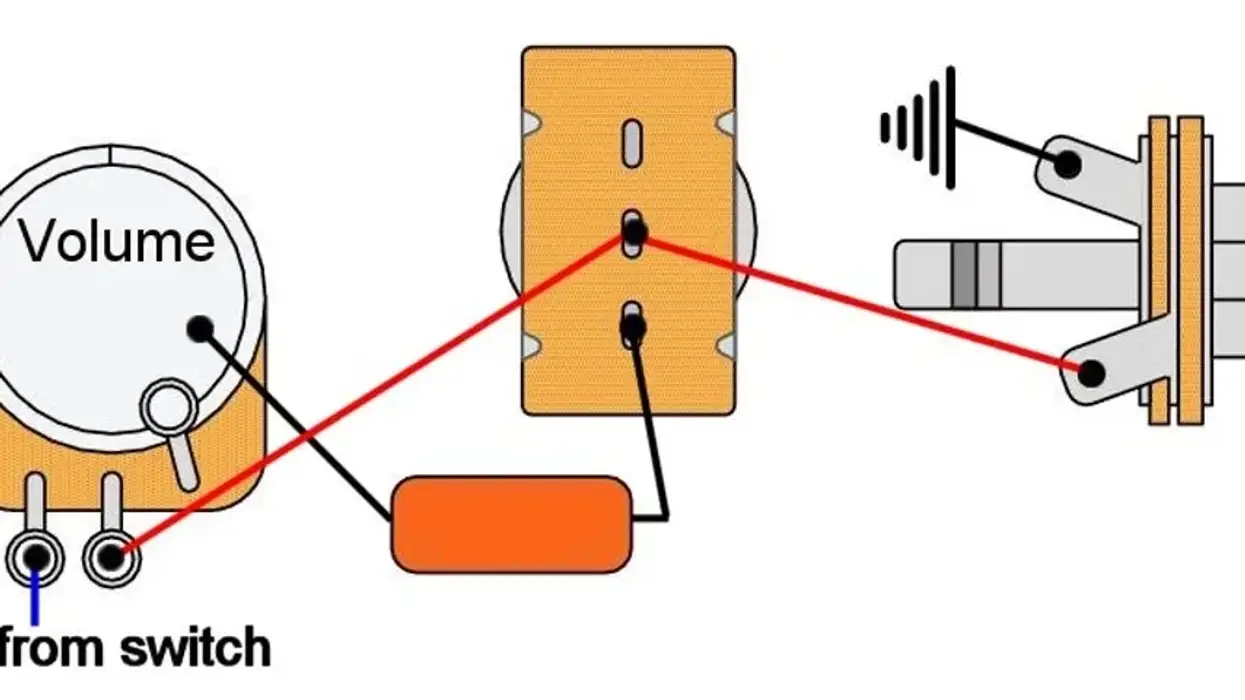
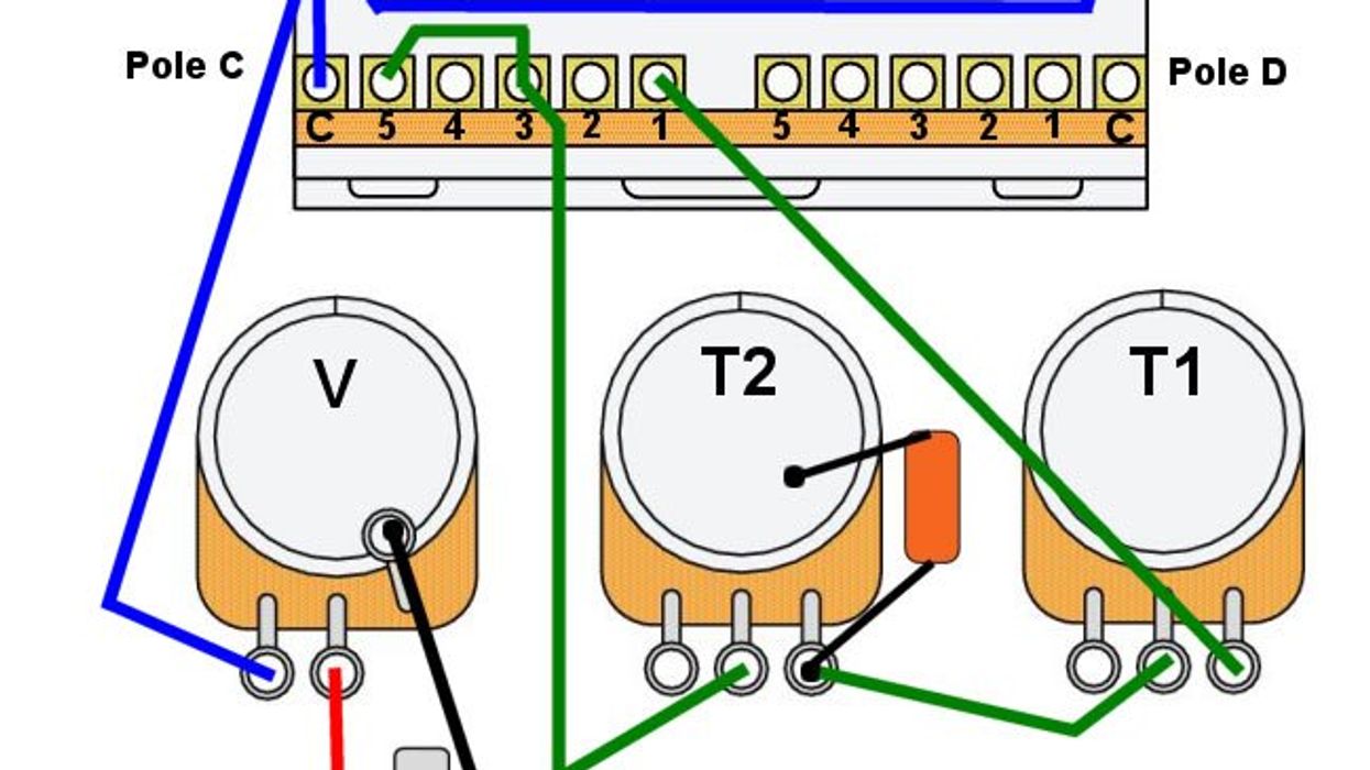
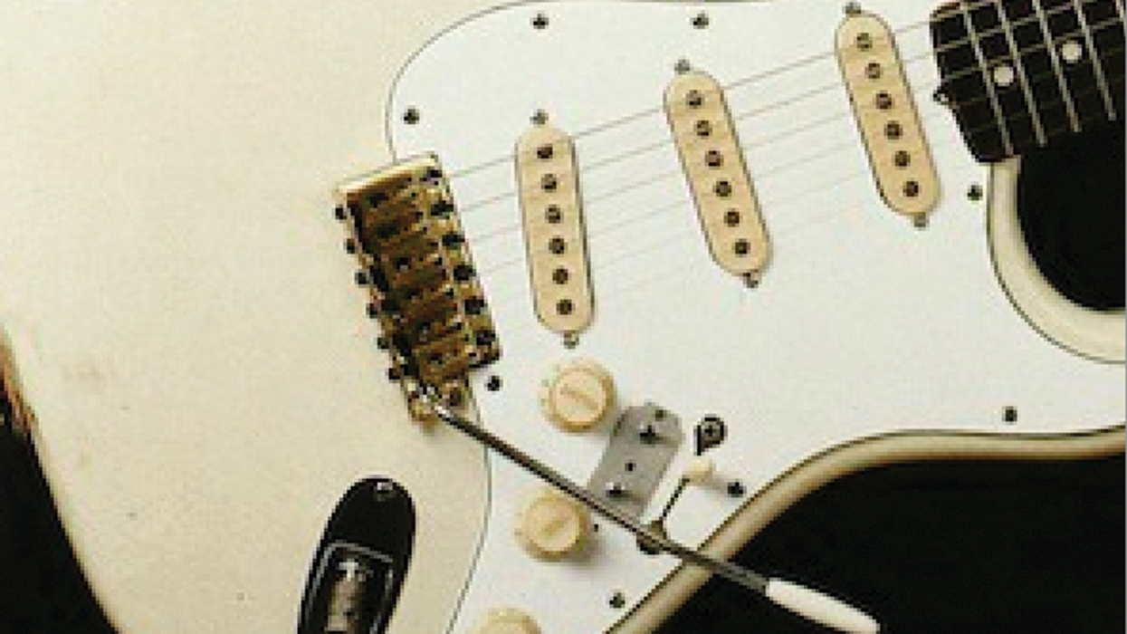
Mod Garage Mod Garage: The Scott Henderson S-Style Wiring This guitar wiring is special in that the two tone controls are freely assigned, and the tone control is bypassed in the two in-between positions. Let’s go under the hood. Dirk Wacker Feb 17, 2023
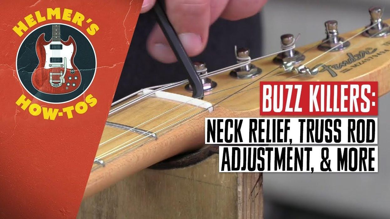
Helmer's How-Tos DIY: How to Adjust Your Guitar's Neck Relief & Truss Rod—Plus, Fix Your Action | Helmer’s How-Tos Dave Helmer Oct 17, 2022