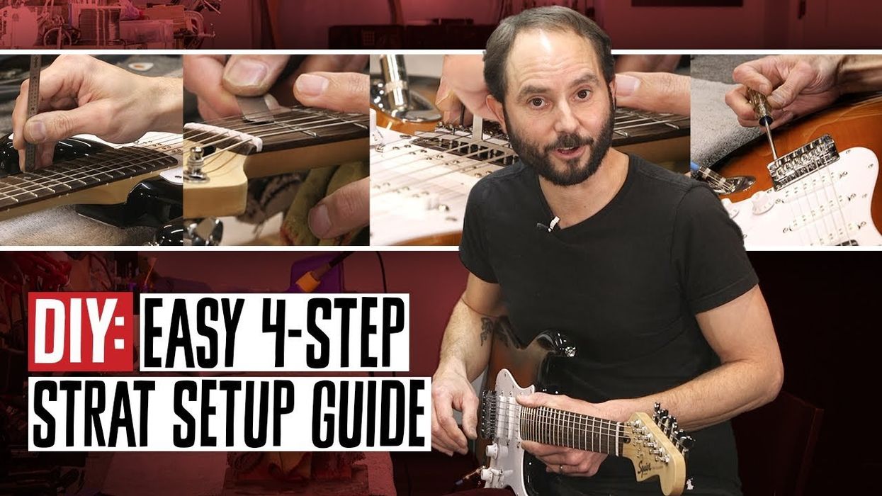

Modding a guitar yourself doesn’t need to be scary. Even if you don’t have any experience working on your instrument, taking things step by step can yield some amazing results.
What you’ll need for this project:
Parts and Supplies
- Three Seymour Duncan JB Jr. pickups
- Pure Tone Multi-Contact Output Jack
- .022MFD orange drop capacitor
- Two 500k CTS potentiometers
- One push-pull pot DPDT on/on switch assembly
- 60/40 rosin core solder
- 22 AWG non-shielded PVC-insulated circuit wire
- Heat shrink tubing
- Small zip ties
- Guitar string set
Tools
- Soldering Station
- Small clippers
- Small round-nosed pliers
- Phillips screwdriver
- 1/2" nut driver
- Strip of painter's or masking tape
- A small jar with a lid
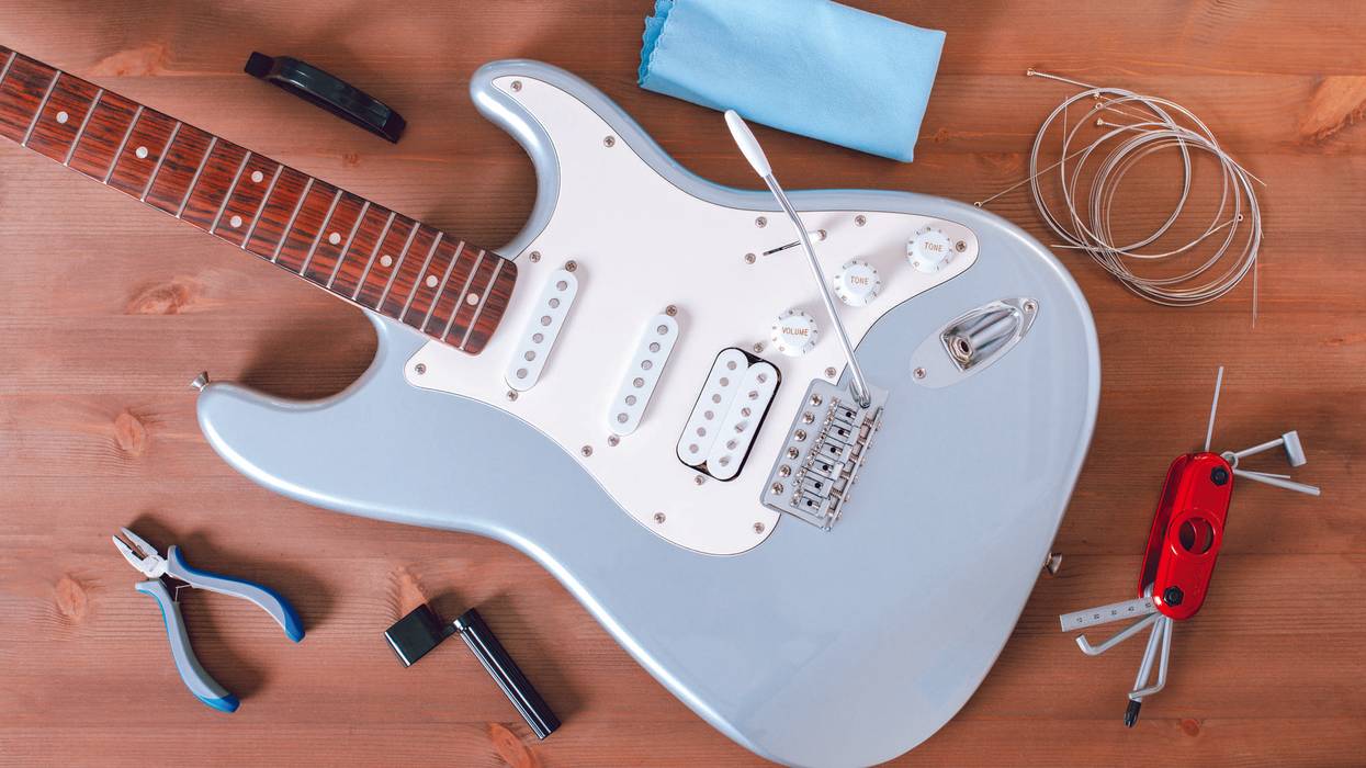
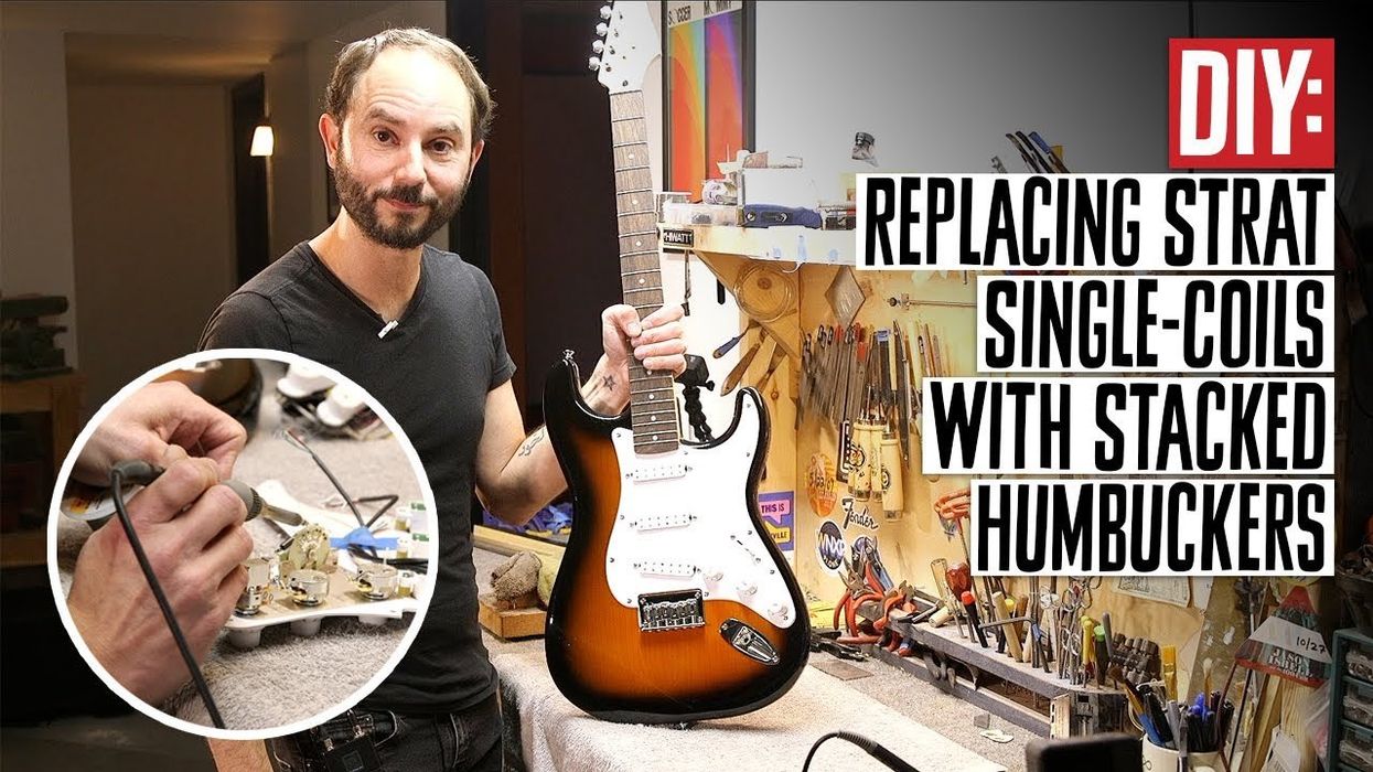
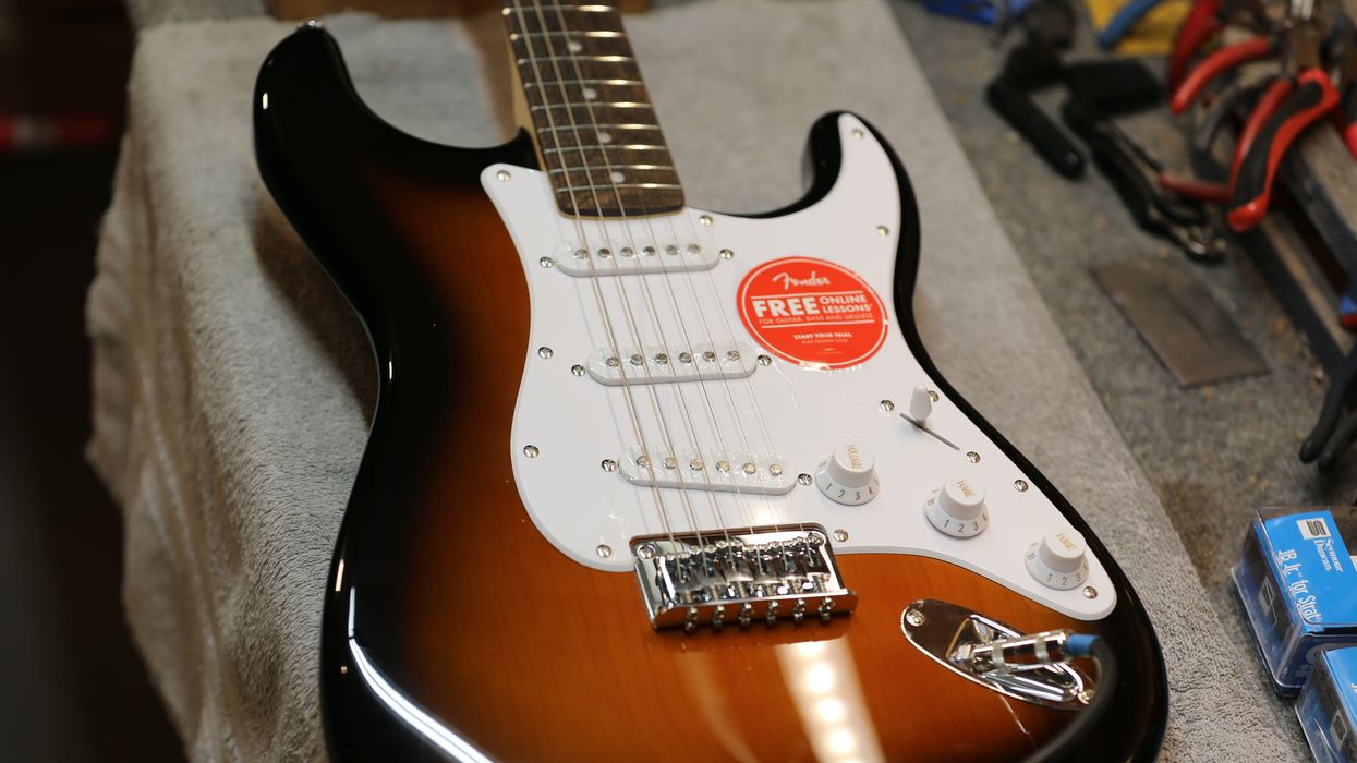
For example, I’m going to show you how a hardtail Squier Bullet Strat, which you can pick up for less than $200 street, can be transformed into a more versatile tone machine by non-invasively replacing its stock single-coil pickups with humbuckers and installing a push-pull pot for coil-splitting the neck and the bridge pickups—where many of the sweet sounds live. While I’m at it, I’ll explain how to install a more durable and efficient jack. Even a beginner can conceivably do all of this over a weekend, and the result will be a very playable guitar with a wide selection of sounds that you can enjoy for many years.
One thing I’ll ask you to do first is brush up on your soldering skills. Unless you’re already on top of those, you should check out “Soldering 101: A Step-by-Step Guide” at premierguitar.com. If you don’t have a good soldering iron—one that’s got controllable temperature settings and speedy thermal recovery—you should get one. I prefer to use a Hakko Soldering Station ($115 street) with digital readouts, and keep the temperature set at 750 degrees Fahrenheit. Here it is, in Photo 1.
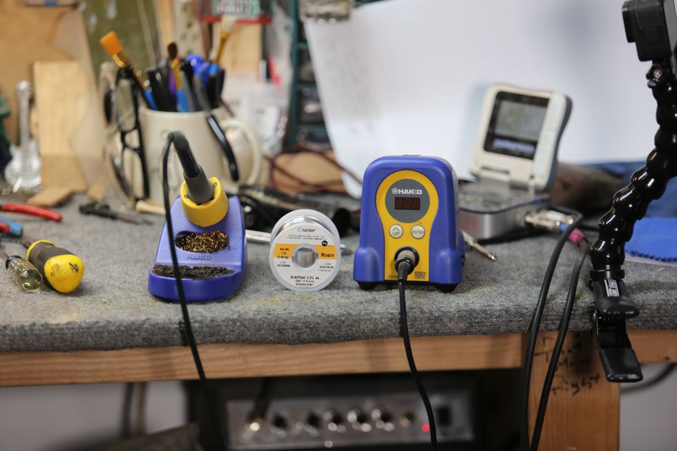
Photo 1
Keep in mind that any iron you use should be at least 40 to 60 watts or it will not get the solder or metal points hot enough. (Twenty-five-watt irons are common, but don’t use them for this job. They are for delicate circuit-board soldering and not point-to-point work.)
I also recommend Kester 60/40 rosin core solder, which is 60 percent tin and 40 percent lead, in .062" thickness. It’s perfect for electronics. (Note: Wear a face mask, like an N95, or work in a very well-ventilated area when soldering.)From Single-Coils to Humbuckers
The first step occurs before the guitar reaches the workbench. We ordered three Seymour Duncan JB Jr. Strat pickups ($99 each), in Photo 2, which are single-coil-slot-sized humbuckers that, after being swapped in, will bump the upper mids and overall output the Squier Bullet Strat produces considerably.
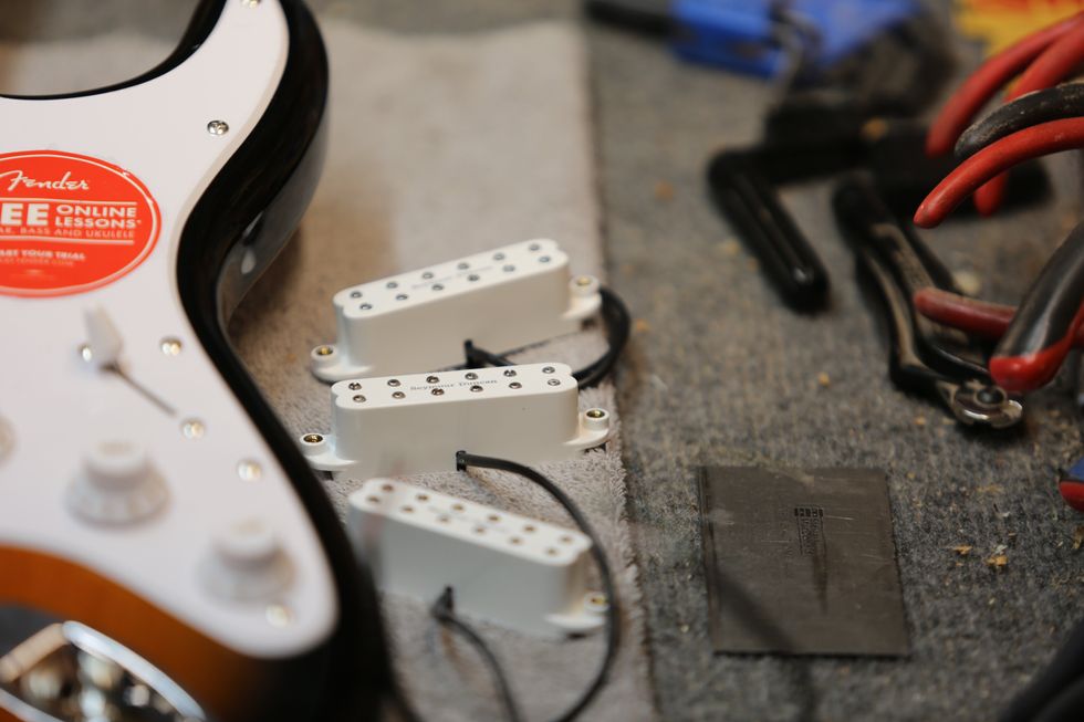
Photo 2
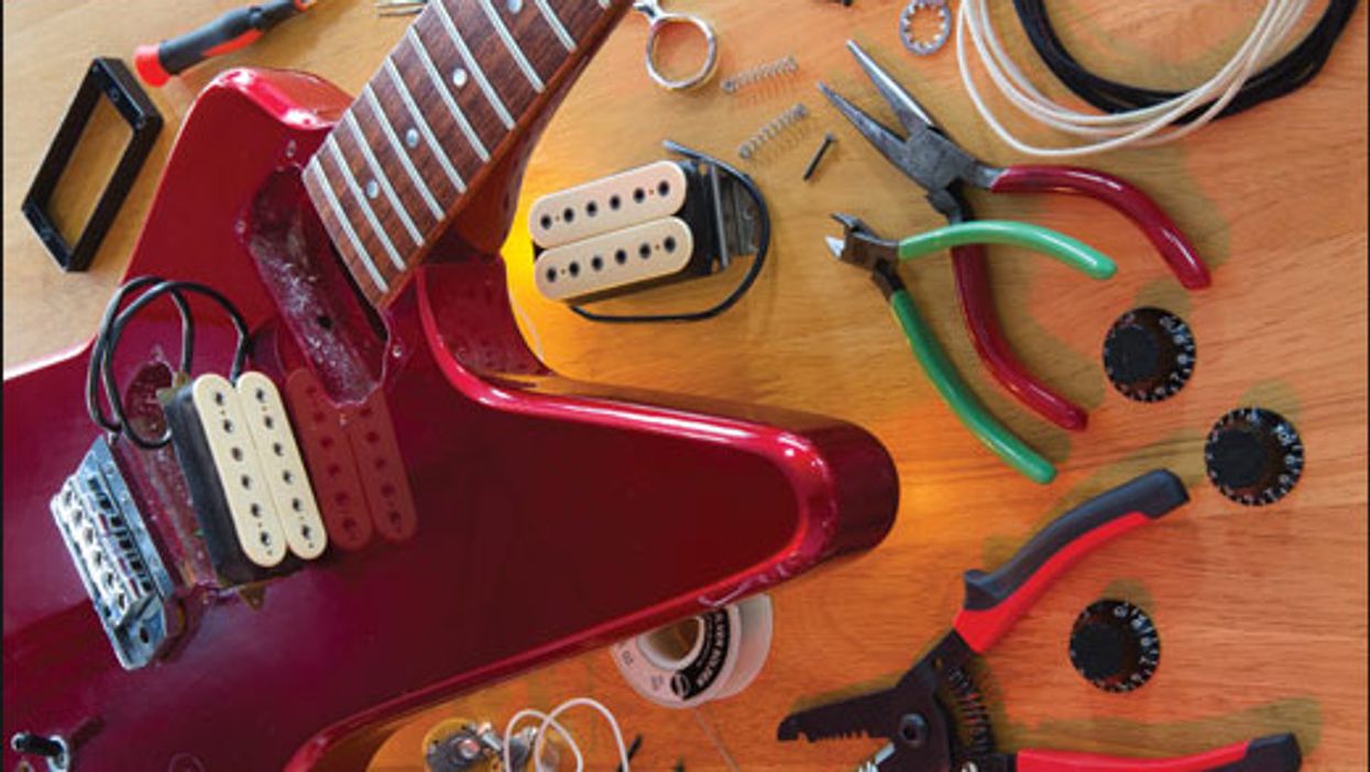
For this mod, you’ll also need two 500k pots (we chose the CTS brand), and one 500k push-pull pot/DPDT switch—all easy to find online and displayed along with the clippers and pliers needed for this project in Photo 3.
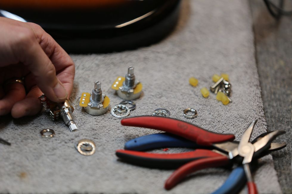
Photo 3
Now, let’s get to started!
1) Detune the guitar to avoid flying-string accidents. Then, using a small wire cutter, clip the strings and remove them from the guitar. Remove the pickguard screws to release the pickguard. Put the screws in a small jar with a lid and put them aside, clear of the work area. You don’t want to be on your hands and knees looking for these later.
As you lift the pickguard, you’ll need to slide it slightly out from around the neck to pull it clear. Then, turn the pickguard over so you can see the wiring harness for the electronics.
2) Next, you’ll want to clip the ground wire that runs from the bridge to the volume pot (this wire looks like it’s coming out of the body of the guitar), as well as the white output-jack ground wire, which runs between the volume pot and an output-jack lug or pin—the small horn-like protrusion from the jack designed to accept wires. Then, clip the red, or “hot,” wire, which carries the signal to the output jack, from the center pin of the volume pot. Now, the pickguard is separated from the guitar and can be placed on an open, convenient spot on your workbench, for the next steps.
3) It’s time to strip the pickguard. After clipping the wires that run from the pickups to the volume pot casing switch, you’ll need to unscrew the pickups from the pickguard and pop them out.
Then, remove the screws—which go into your jar—on the 5-position pickup selector switch and gently remove its plastic top by pulling up on it. Now, you can pull the 5-way switch out of the bottom of the pickguard and save it for the rewiring process. You could leave the 5-way in place instead, but removing it gives you more space to work on the rest of the pickguard electronics assembly.
To remove the pots, gently pull up on the knobs and they will lift off the face of the pickguard. If they resist, consider using a cereal spoon to pry the dials up, and perhaps place a thin piece of cloth, like part of a t-shirt, under the spoon to keep the pickguard scratch-free. This method is less hazardous to the pickguard than using a flathead screwdriver.
Next, unscrew the nuts on the front of the pickguard that hold the pot assemblies in place. (They were revealed after you lifted the dials up.) You’ll probably need a pair of pliers to loosen them a bit, but, again, be careful not to scratch the pickguard. Turn the pickguard over again and clip the wires from the pots, which—reminder—we’re replacing, so don’t worry about saving them. (Standard CTS pots sell for about $7—cheap.) Then, the pots should pop right out. In Photo 4, from a bit later in the process, the pots, DPDT switch, and pickups have already been reinserted, but you can use this photo to view the nuts around the tone and volume control spindles.
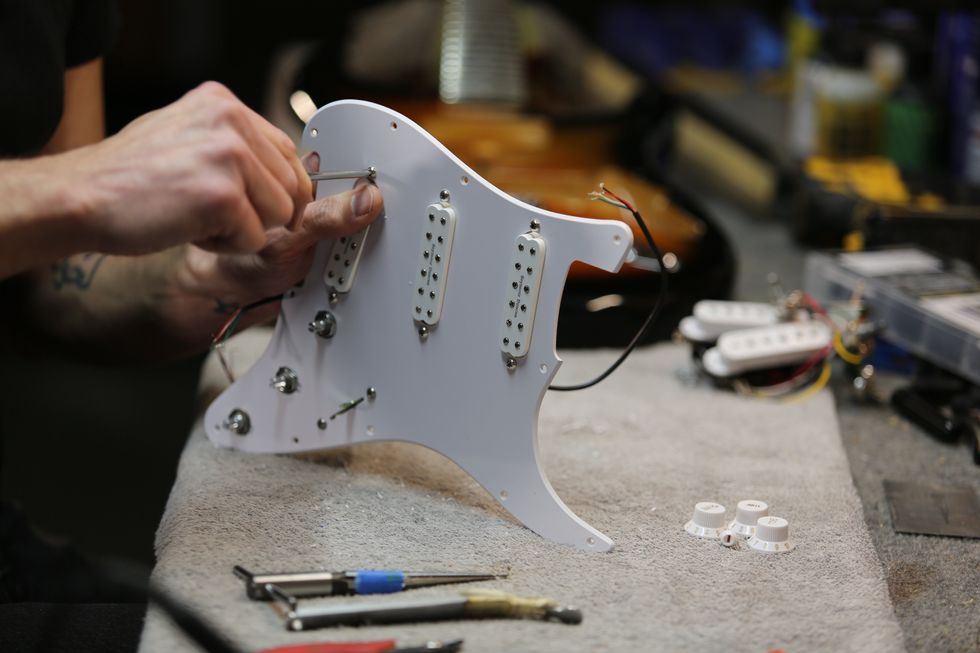
Photo 4
4) Now, it’s easy to install the JB Jr.’s on the pickguard. Simply pop them through the pickup slots and screw them in place. Make sure the top of the letters reading “Seymour Duncan” face the neck for all three pickups, as in Photo 4. Use two small zip ties to keep all three four-conductor wires from the pickups together, and a piece of painter’s tape to temporarily hold the loose ends of those wires to the pickguard after the pickups are screwed in tight, to prevent the pickup wires from getting in your way as you work on other steps.
5) Time to install the new pots in the volume and first tone control positions, and then to install the push-pull DPDT switch in the tone control position closest to the guitar’s heel—the one farthest from the strings. While 250k pots are good for single-coil pickups, we’re using the 500k pots that are best for humbuckers here. And don’t forget the 5-way switch!
Let’s start by placing both pots and the push-pull in their places, sliding the shafts through the pickguard openings, and then screwing down the nuts to hold them in place—essentially reversing the process we used to remove the originals. (The 1/2" nut driver that you’ll use for the jack replacement we’ll do next also works for screwing down the nuts.)
Likewise, to reinstall the 5-way pickup selector, simply find your two screws and reverse how you removed it.
6) Basic Strat-style wiring—mostly—is the next step. A good standard Strat wiring guide, like the one on the Seymour Duncan website, may be a helpful visual aid. Wire the volume and tone pots to the switch exactly as on the diagram.
Duncan’s JB Jr.’s come with about 10 inches of four-conductor circuit wire already attached. Strip off about 3" of that wire’s outer casing. Then, you’ll see red, white, black, green, and ground wires. Peel about 1/2" of casing from the tips of each of those smaller, color-coded wires.
For the neck pickup, the green and bare wire are tied together and attached to ground—soldered to the top of the middle (tone) pot. You can see the secured pickup leads, ground soldering location, and overall layout in Photo 5.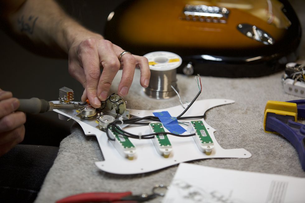
Photo 5
The red and white go to the center right pin (looking from the smooth rear of the push-pull pot) of the on/on DPDT switch atop the push-pull pot. The black wire goes to the corresponding pin on the 5-way switch—the third lug from the front. (Reminder: Always tin your solder points!) You can get a good look at the DPDT and push-pull pot assembly in Photo 6.
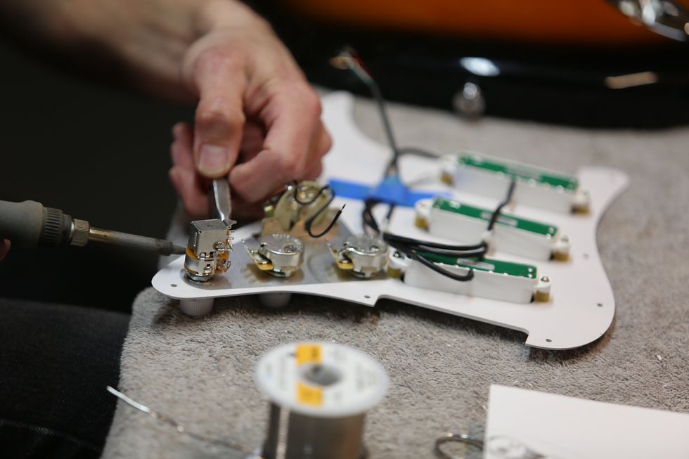
Photo 6
For the middle pickup, the red and white wire are soldered together and bent back over the lead wire. You should use a piece of heat shrink tubing to mask it off. (Heat shrink tubing for guitar and bass wiring can be purchased via a number of online sources.) The green and bare wires also go to ground atop the tone pot, and the black wire goes to the number two lug on the 5-way switch.
And finally, the bridge pickup. The green and bare are tied together and, once again, soldered to ground on the top of the tone pot, while the red and white go to the left middle pin on the DPDT switch atop the push-pull pot, and the black wire goes to the corresponding pin—the front slot—on the 5-way switch. That provides coil-splitting, activated for the neck and bridge pickups, by pulling the rearmost knob up.
7) Let’s do one more thing while we’re here to beef up the tone. Let’s put a .022MFD orange drop capacitor in the tone control’s setup, which will roll off less treble frequencies than a higher value capacitor as the tone knob is turned down. The cap can rest atop the center (tone) pot, and let’s solder one of its bare wires to the back of the same pot’s casing for grounding. We’ll take the other wire and shield it with shrink tubing, and solder it to the outside pin on the tone pot. In Photo 7, you can see the completed wiring for the control set.
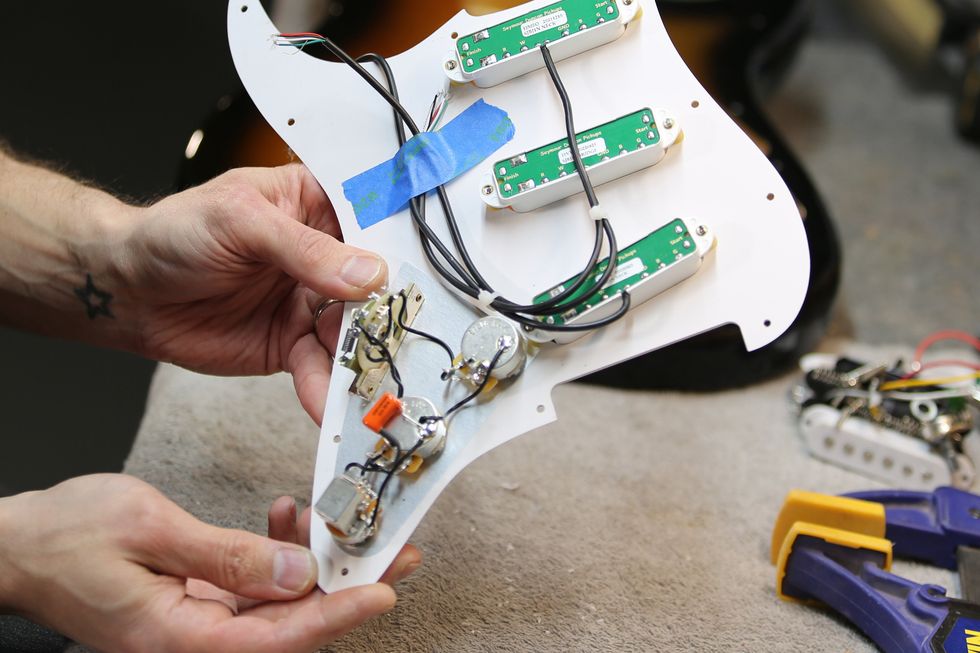
Photo 7
8) There’s one more control set wiring move.
The bottom lugs of the push-pull DPDT switch are both jumped to ground. This is what makes the coil-splitting possible, by selecting the ground wire or allowing it to go to output. (Use 22 AWG non-shielded PVC-insulated circuit wire for incidental wiring work like this.)
Then, reattach the red output wire from the output jack to the center pin of the volume pot. Follow that with reattaching the bridge ground wire and output-jack ground wire to the back of the volume pot casing.
(Or, you can wait and do these steps later if you are also doing the jack replacement.) Photo 8 displays all of our handiwork!
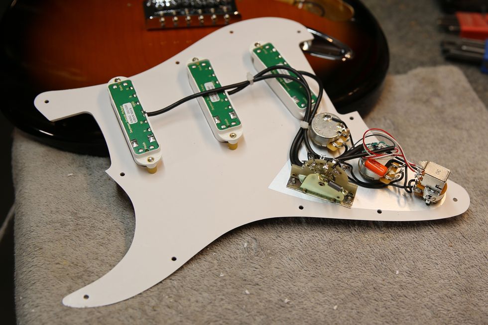
Photo 8
9) Lastly, replace the pickguard back onto the guitar with the screws you’ve saved and plug the guitar in to test the connections before screwing it back on. Done!
DIY: Replacing Strat Single-Coils with Stacked Humbuckers
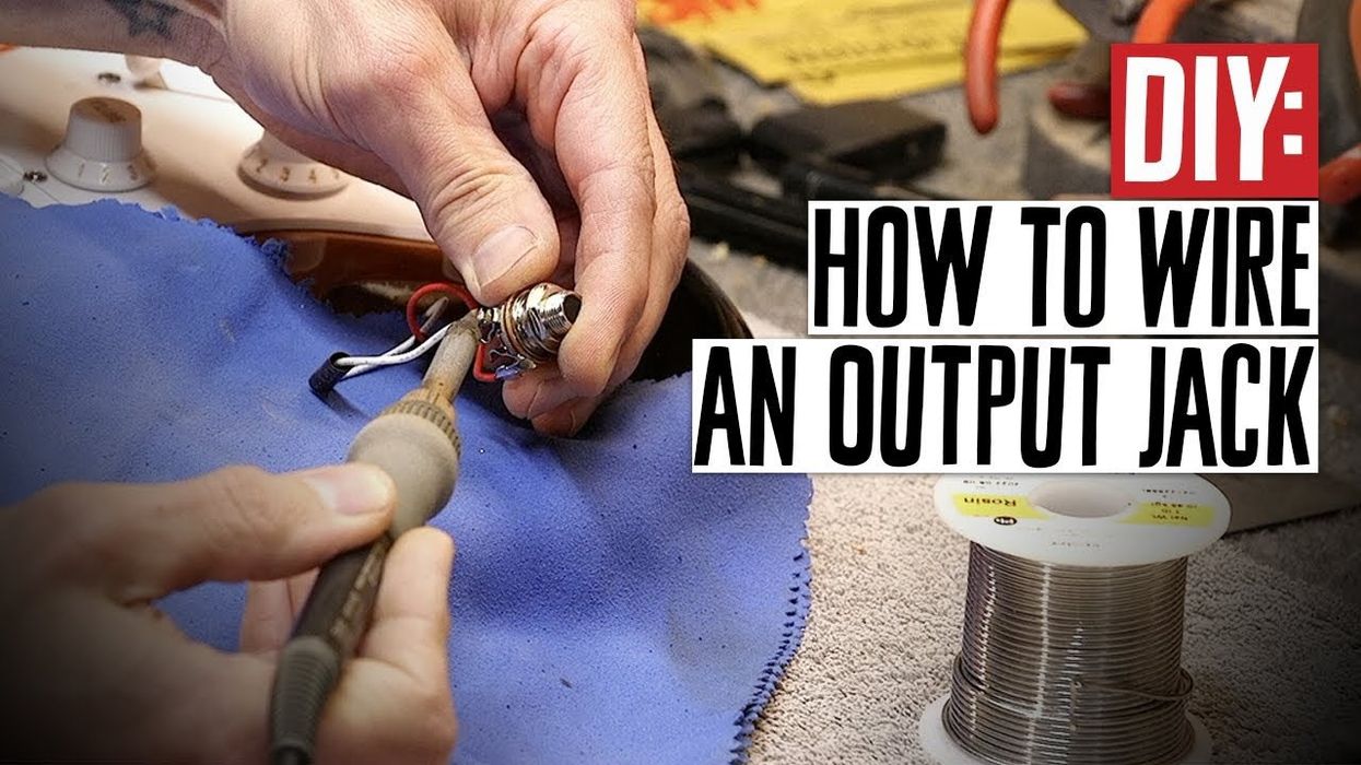
Swapping the Output Jack
Our next job is replacing the standard 1/4" jack that lives behind the chrome boat-style output receptacle with a Pure Tone Multi-Contact Output Jack. It has four points of contact, versus the OEM’s two, and dual tension grounds to hug the cable sleeve in place from both sides, providing more reliable performance and better tone.
1) Start by removing the two jack-plate screws, and then remove the output-jack nut with a 1/2" nut driver. Carefully pull out the jack and boat assembly, (Photo 9) and snip the lead wires—the red is hot output and the white is ground—close to the jack, leaving plenty of wire from the guitar’s harness to work with. Strip the leads of those protruding wires about 1/4", for soldering later.
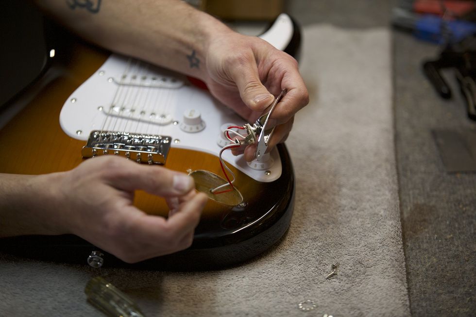
Photo 9
2) Grab your 60/40 rosin core solder and bring your soldering iron up to 750 degrees. While the iron’s heating up, slide some heat-shrink tubing down the output and ground wires. And when the soldering iron is at temperature, tin the wire leads and pins on the Pure Tone replacement jack.
3) Next, solder the hot (red) output and ground (white) wires to the two pins on the jack, being tinned in this photo (Photo 10).
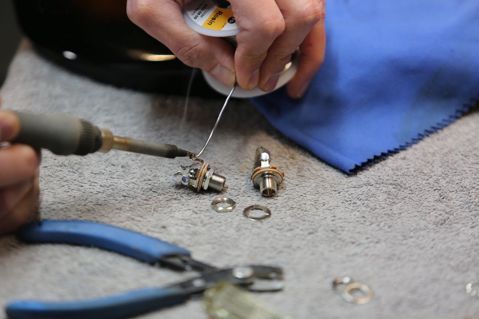
Photo 10
When you’re done, slide the heat-shrink tubing that you slid onto the wire earlier over the pins and solder points. Then, heat the tubing with either a heat gun, hair dryer, or lighter (Photo 11) to make them shrink.
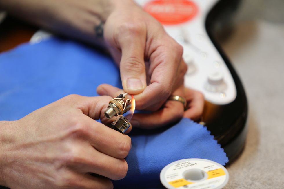
Photo 11
4) Finally, reattach the new output jack to the jack plate with a locking washer underneath, tighten the output-jack nut with the 1/2" nut driver, and reattach the jack plate to the body with the original jack-plate screws, as in Photo 12.

Photo 12
And now you’re ready to plug in and play!