In last month’s column on mid-’70s Fender Twin Reverbs I mentioned that some undesirable post-’68 circuit changes could be reversed. This month’s column covers small circuit modifications you can make to improve the sound. We’ll also be disabling the amp’s push/pull distortion feature, but hey, nobody I know uses it, so no love lost there.
First, though, a quick answer to another Twin Reverb question:
Hi from France, Jeff!
Am I wrong, or is one of the important changes affecting the tone of some of these amps the use of an ultra-linear scheme? Thanks again for all the great information.
Best,
Thierry
You are correct, Thierry. In 1976 or ’77, Fender incorporated another major revision to the Twin Reverb design, changing the output stage to an “ultra-linear” design and increasing the output power. This required a differently designed output transformer. They also changed the mains (power) transformer and markedly increased the high voltage applied to the output tubes. These amps can be identified by their output power, listed on the rear panel near the speaker jacks as 135 watts. These are the loudest and cleanest of all Twin Reverbs. This displeases many players, who want to be able to crank their Twins to get distortion, which is almost impossible with these amps. Having said that, these amps are quite popular with jazz and country guitarists who want a very loud, clean amp, as well as players who use them as clean platforms for pedals.
Now on with the modifications!
One of the main areas in which master volume Twins differ from their predecessors is the phase-inverter circuit, so we’ll start with a few quick modifications here. These open up the amp a bit and provide better feel and response. (Note: All resistors should be at least ½ watt. Personally I prefer 1-watt resistors for amp building and repairs.)
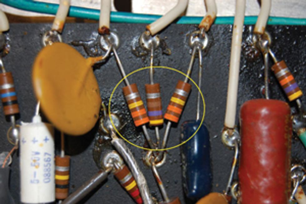
Fig. 1
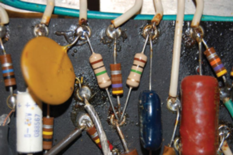
Fig. 2
Locate the two resistors (Fig. 1) connected to the grids of the 12AT7 phase-inverter tube, which are pins 2 and 7. In the ’70s master volume version of the amp, these resistors’ values are 330K (orange, orange, yellow). We’re going to remove these resistors and replace them with 1M (brown, black, green) resistors (Fig. 2).
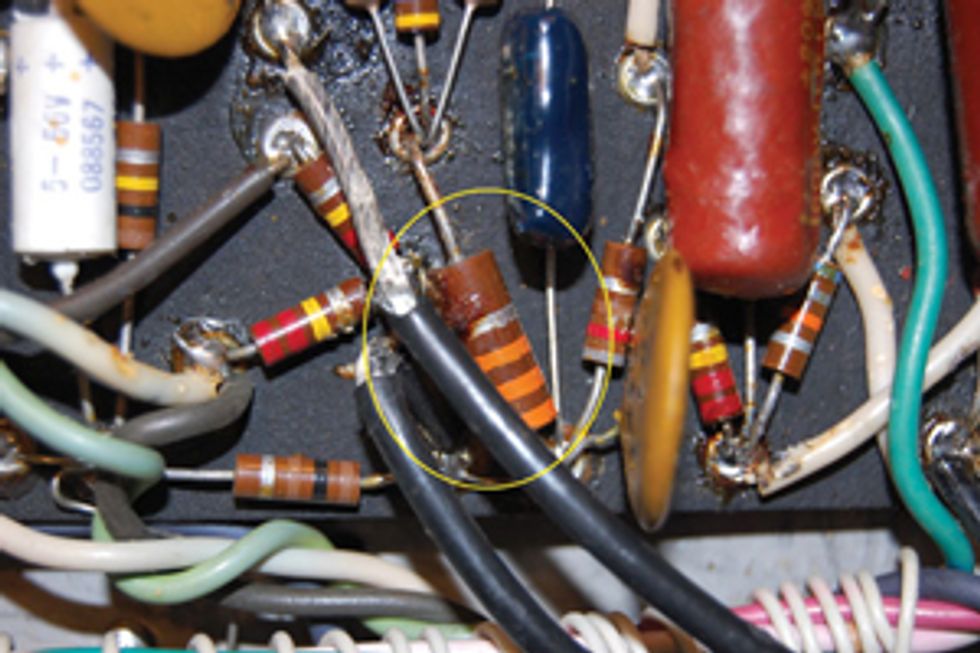
Fig. 3
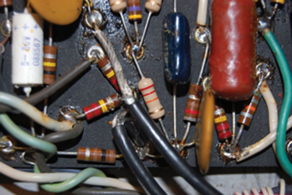
Fig. 4
Next, locate the 33k resistor (orange, orange, orange) in the same area (Fig. 3) and replace it with a 22k (red, red, orange), which takes care of the input stage of the phase invertor (Fig 4).
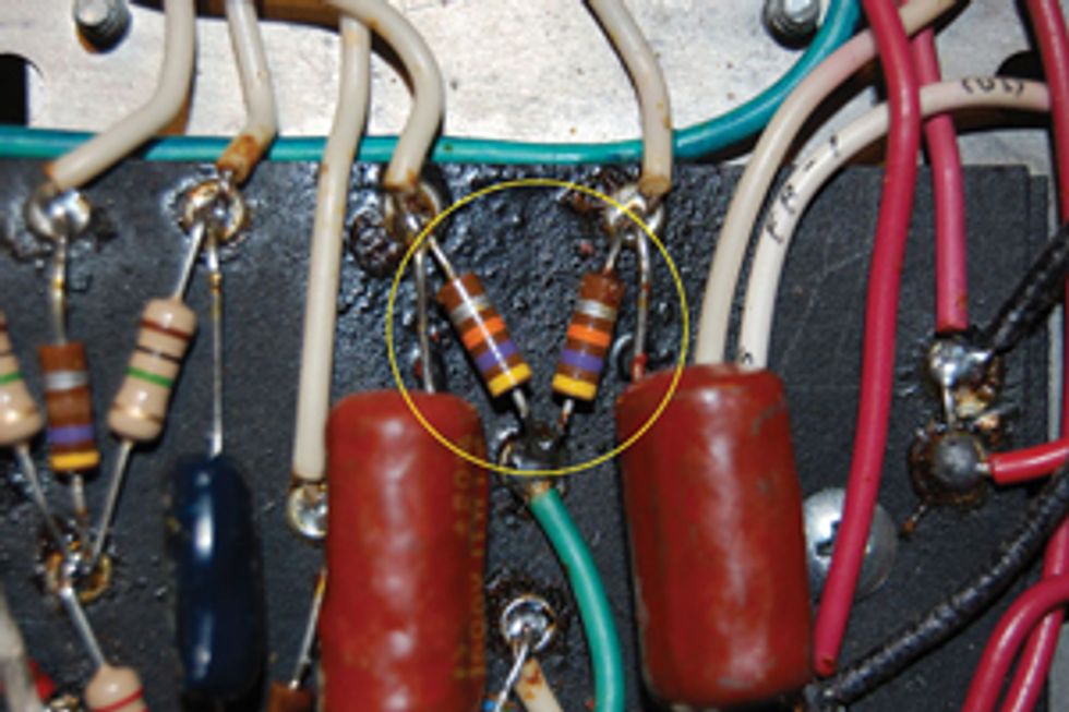
Fig. 5
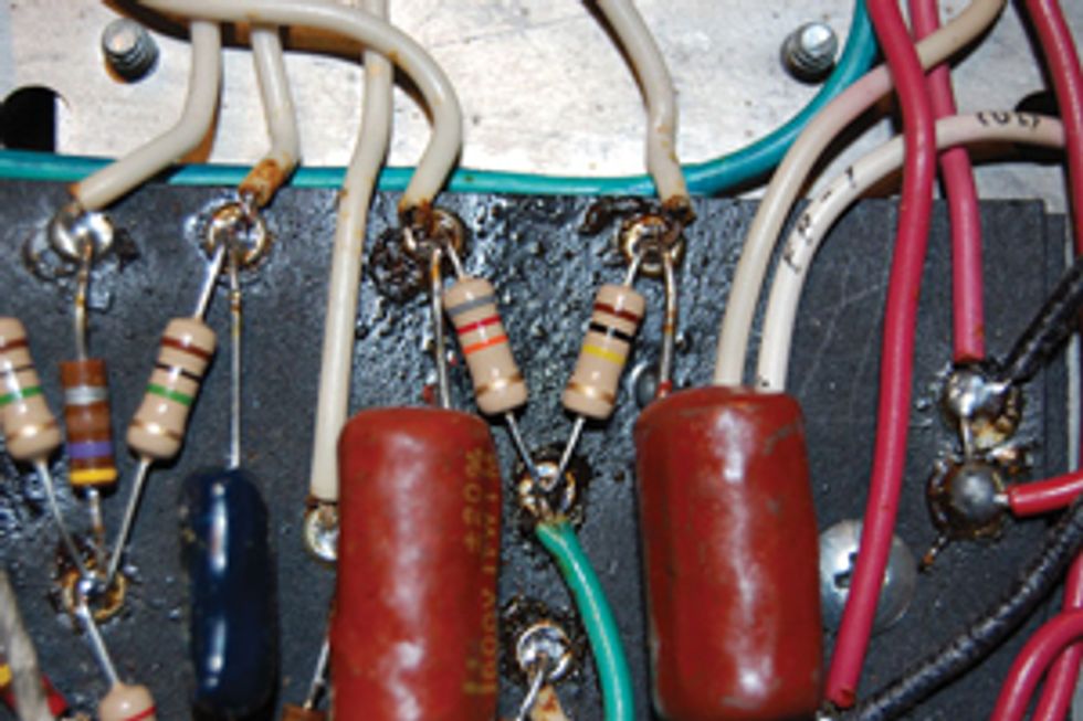
Fig. 6
Now let’s move on to the phase inverter’s output. Locate the two 47k resistors (yellow, violet, orange) connected to the plates of the same tube (Fig. 5), which are pins 1 and 6. Remove both 47k resistors. We’ll replace them with resistors of two different values. Replace the resistor connected to pin 1 of the 12AT7 phase inverter with an 82k (gray, red, orange). Next, use a 100k resistor (brown, black, orange) to replace the resistor connected to pin 6 (Fig. 6). You’ve now completed the phase inverter updates.
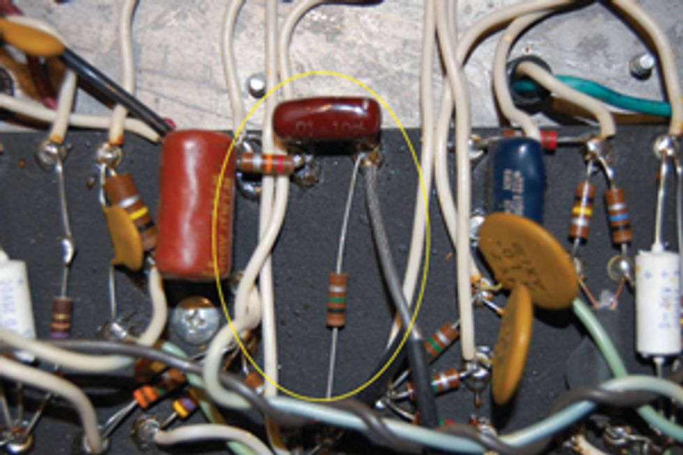
Fig. 7
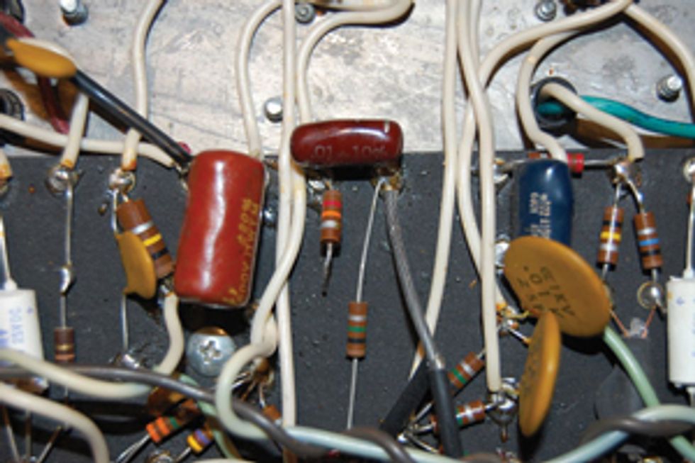
Fig. 8
Next, let’s get rid of the unnecessary components in the overdrive circuit that put a bit of a load on the signal. Around the center area of the circuit board is a 1M (brown, black, green) resistor connected to a .01uf capacitor, with the capacitor connected to a 12k (brown, red, orange) resistor (Fig. 7). These components are only necessary when the distortion function is engaged, but they exert a small load on the signal just prior to the master volume. Simply lift the side of the 12k resistor connected to the 100k and 0.1uf capacitor (Fig. 8).
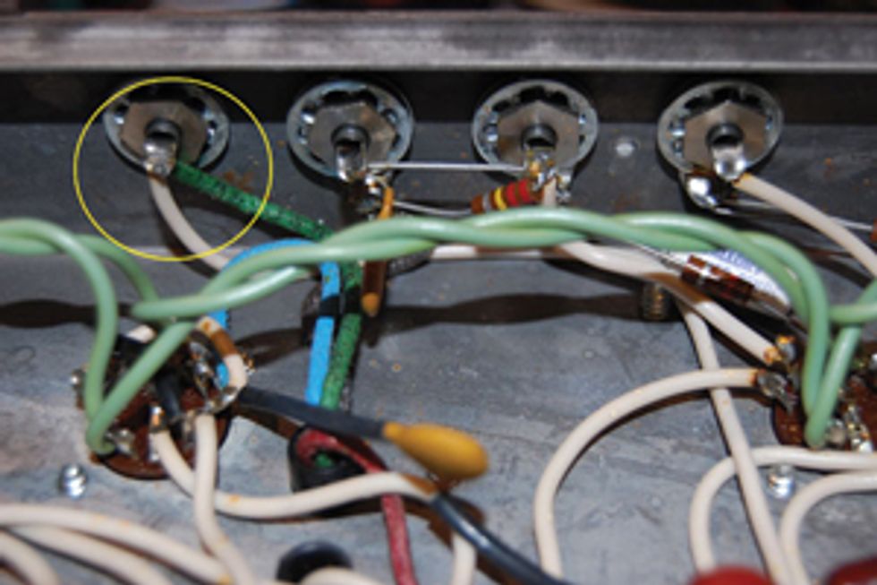
Fig. 9
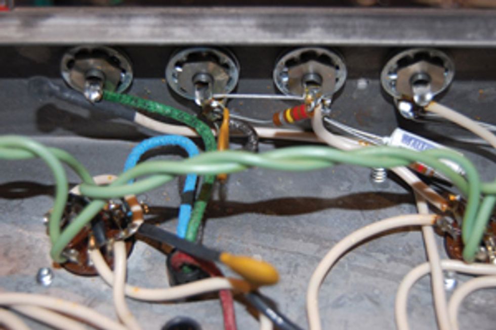
Fig. 10
Now there’s only one more change: Across the rear panel of the amp are four RCA jacks. The one closest to chassis’ edge is for the reverb pan input. This is also where the signal is derived for the amp’s distortion mode. Along with the green reverb drive transformer lead you’ll also see a white wire connected to this jack (Fig. 9). Simply remove the white wire and cover the exposed end with tape or shrink-wrap (Fig 10). This removes the drive signal to the overdrive circuit should the function be accidentally engaged.
Well, there you have it. You should find that these modifications open up Twins of this era, transforming them from strident and lackluster amps to ones with more character and chime that simply feel better to play. Enjoy!
Thanks to Dave Nachodsky and Joe Rinaolo at the North American Guitar Amp Museum for supplying this 1974 Twin Reverb and making these great pictures possible. This particular specimen is rumored to have once been the touring amp of one Richie Havens. Fitting that we just gave it some freedom!