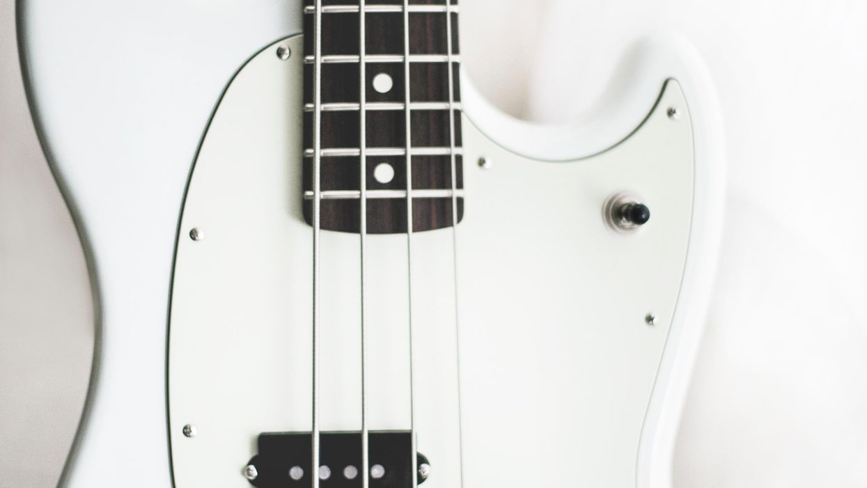

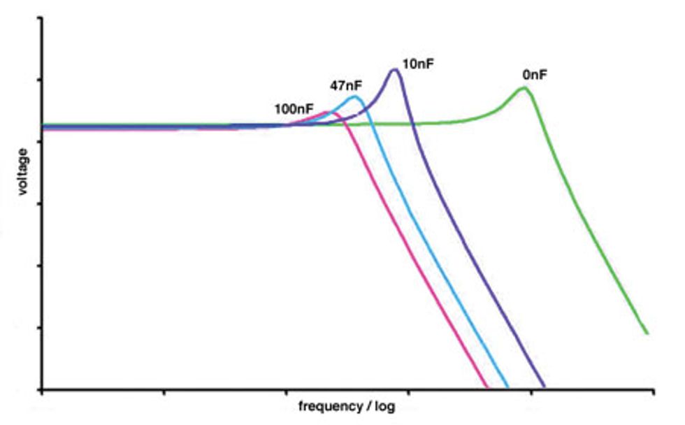
Fig. 1
Different capacitors in a treble blend circuit altering the cutoff frequency. Image courtesy of basslab.de
It has been a while since we looked at tone controls. (The last time was my June 2012 column “Active Versus Passive Tone Controls," which focused on the pros and cons of each system.)
While active systems usually work comparably to the multi-band tone controls we have in our amps, passive systems are most often represented by the simple treble blend. Doesn't look like a fair comparison, right? But in fact, there are many possible ways to use passive elements to control tone, and our guitar colleagues constantly discuss them in great detail. This type of modding is far less popular among bass players, so let's consider what passive systems offer and see if they can be useful to us.
Passive resistance. The number of passive elements used for tone controls is small: just resistors and capacitors and (less often and more theoretically) inductors. The next limitation is that these few elements can only be wired in series or parallel with nothing in between. Still, given the number of varying electrical specs and possible combinations, these simple elements can be deployed in a vast number of ways.
One trait of passive wirings is that almost everything influences everything. That means, for example, that using a given wiring with two different pickups can produce very different results. (Meanwhile, changing pickups with active systems doesn't alter the preamp's behavior at all.) So to get a passive control to regulate a specific frequency, you have to experiment to find the right values for your particular pickups—and sometimes even your amp—or dig deeper into electrical engineering to calculate values before you start. Since not everyone wants to be an electrical engineer, let's go with the experimental approach and focus on schematics and principles, rather than concrete electric values.
Guitar circuits on bass. Don't be afraid to check out guitar wirings on bass. They all work, and you only have to change a few values, but not the circuit itself. Fig. 1 is a reminder of how capacitors of varying value in a standard parallel treble blend can alter the tone (or frequency response) of your pickup. The greater the value of the parallel capacitor, the more high frequencies get cut.
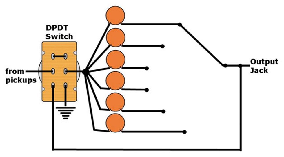
Fig. 2
A capacitor cascade with a DPDT-switch (on/on/on) for a switchable passive bass/treble cut.
Image courtesy of singlecoil.com
One obvious thing you could build from this is a simple SPDT switch to activate different capacitors, each removing varying amounts of upper-spectrum frequencies. Here the pot controls the amount of amplitude reduction above the “end of spectrum" roll-off frequency, as determined by each capacitor's value. To expand this further, you could arrange even more caps on a 6- or even 12-way rotary switch. The basic wiring is the same as the simple 2-capacitor wiring. But while the rotary switch is helpful for finding the values that suit your setup and taste, it's not very practical for permanent use.
Bass with less bass? While a switch to remove varying amounts of treble frequencies sounds useful to a bassist, it's harder to imagine what happens if we do the same for the bass range. True, it doesn't appear very useful at first, but then again, even the weirdest sound might meet the requirements of a specific song! Also, with the current popularity of lowered tunings and distortion pedals for bass, such bass-cuts can clean and clarify muddy low end.
To cut bass frequencies, all we have to do is rewire the capacitors from parallel to serial. Also, while higher-value parallel capacitors remove more treble frequencies, the opposite is true for bass: lower serial values mean greater bass frequency cuts. Using an extra DPDT switch and some wiring, it's easy to expand the rotary switch circuit to a switchable bass-cut/treble-cut wiring with a quick bypass (Fig. 2).
Assuming you've found your favorite capacitor values for both bands (and omit the rotary switch), you end up with independent treble and bass controls. To some extent, that's similar to the controls of an active system, yet the results sound very different. While the active tone control bends the spectrum by changing the amplitude of a given frequency range, the passive control almost cuts off the frequency range at its ends. Another difference: The passive control can reduce frequencies, but never increase them.
Passive treble and bass controls still leave us with a question: How can we control mids? More on that next month, along with some wirings that were once so popular, they earned their own names.