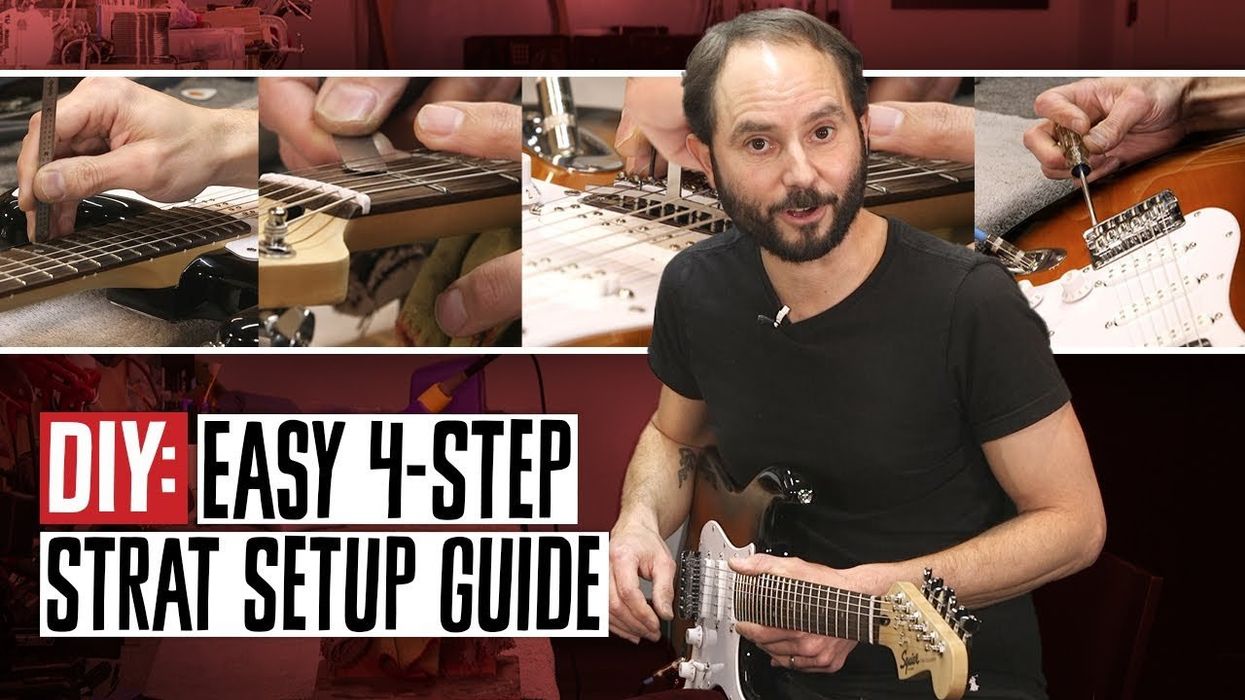
www.youtube.comDIY DIY: Master the Art of Guitar Setup in Just 4 Simple Steps Dave JohnsonDec 26, 2023
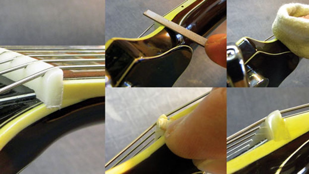
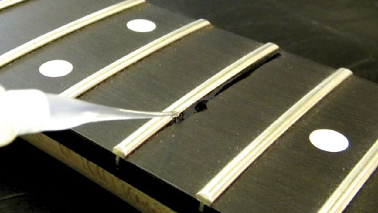
Guitar Shop 101 Guitar Shop 101: Using Super Glue in Guitar Repair The fast-acting adhesive can work wonders ... if you know how to handle it safely.John LeVanAug 07, 2016
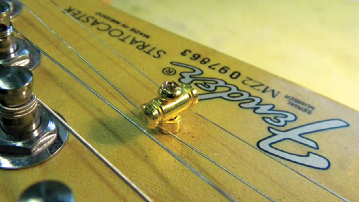
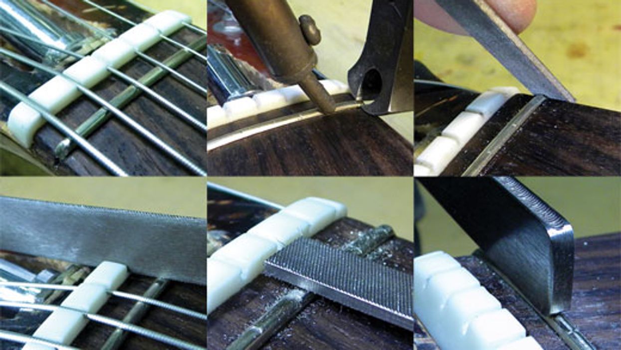
Guitar Shop 101 Guitar Shop 101: Happy Little (String) Trees Do the open strings buzz or sound wimpy on your Fender-style guitar? Maybe the problem lies at the headstock.John LeVanJul 15, 2016
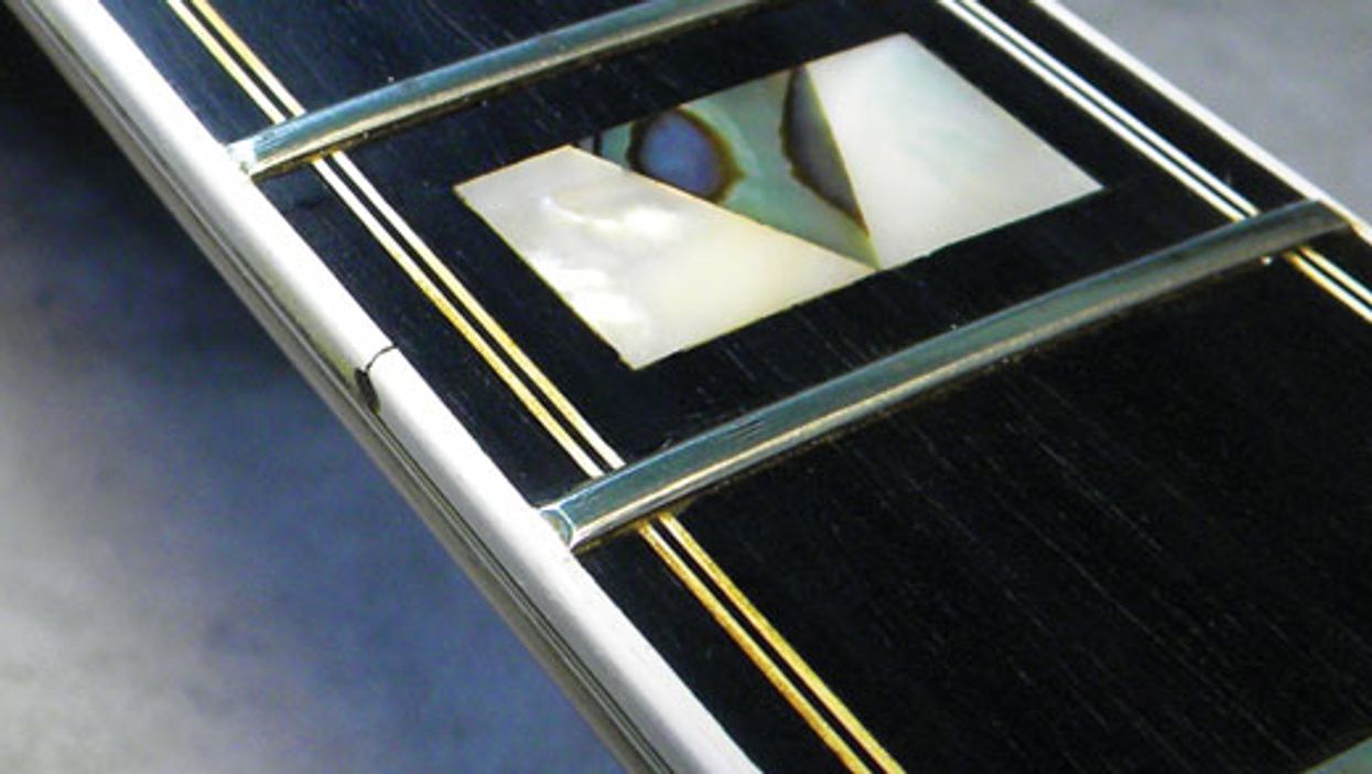
Gear Guitar Shop 101: How to Repair Delaminated Neck Binding Got some loose fretboard binding? No worries—here are a few easy steps to fix it.John LeVanJun 21, 2016
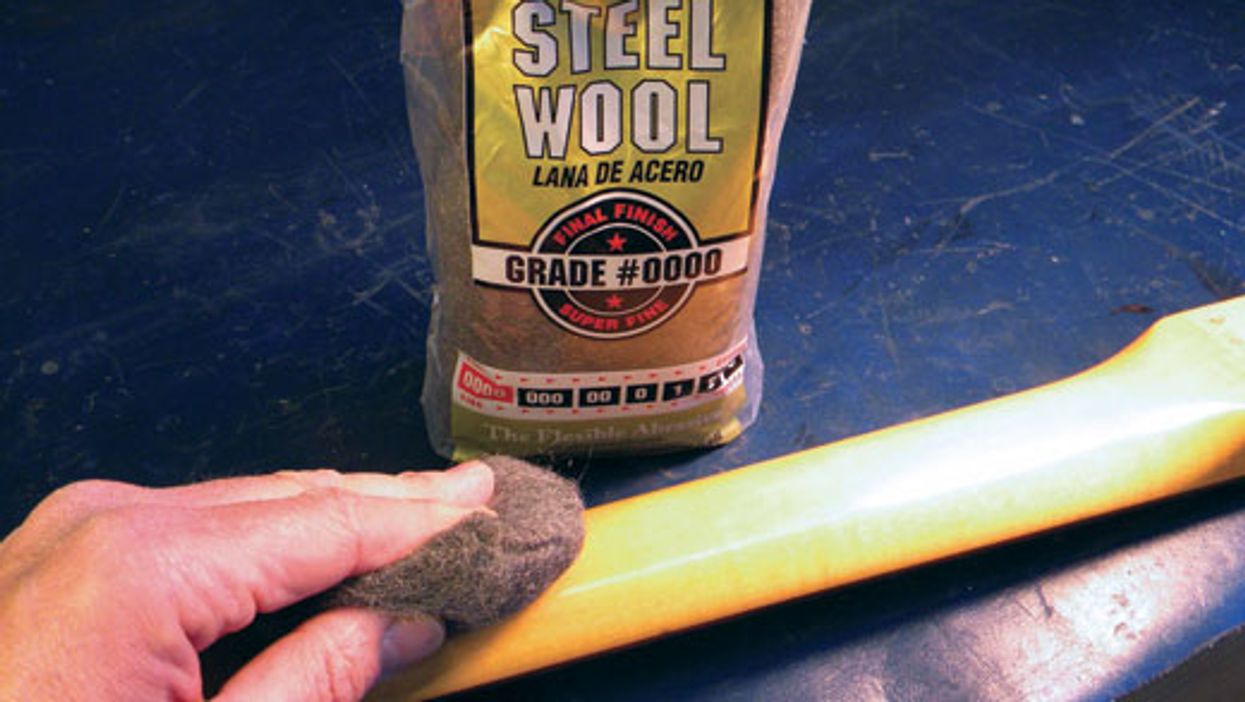
Guitar Shop 101 Guitar Shop 101: Curing Sticky-Neck Syndrome Do you feel like you’re fighting your guitar’s neck? Here’s how to create that smooth, “played-in” feel.John LeVanMay 20, 2016
Gear Guitar Shop 101: How to Replace a Zero Fret Learn how a zero fret functions and why it sometimes needs to be replaced.John LeVanApr 15, 2016
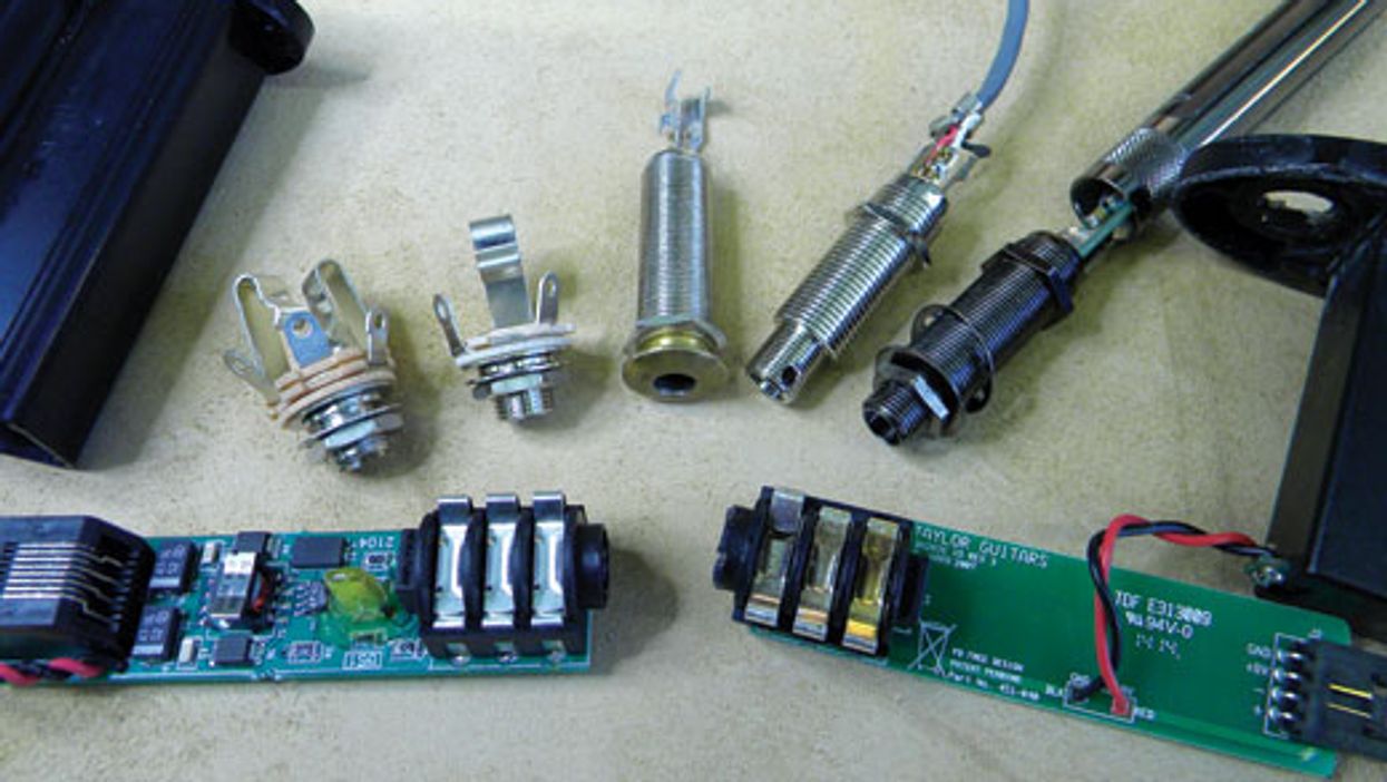
Guitar Shop 101 The ABCs of Output Jacks Passive pickups, active electronics, and acoustic-electric guitars with dual-pickup sources all require different types of output jacks. Do you know how to wire them up?John LeVanMar 25, 2016
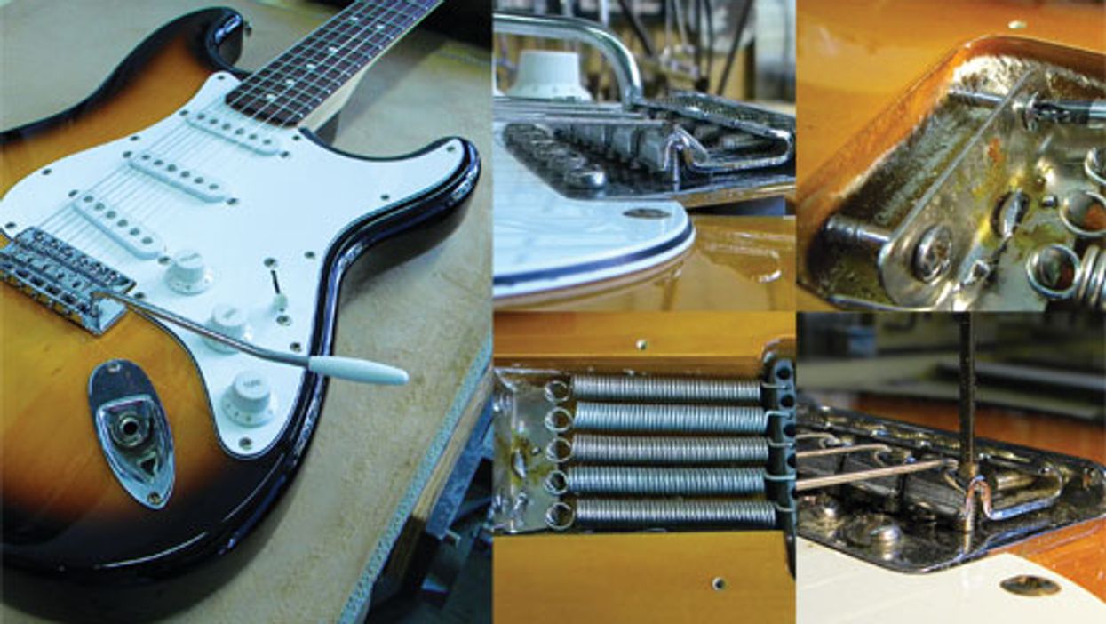
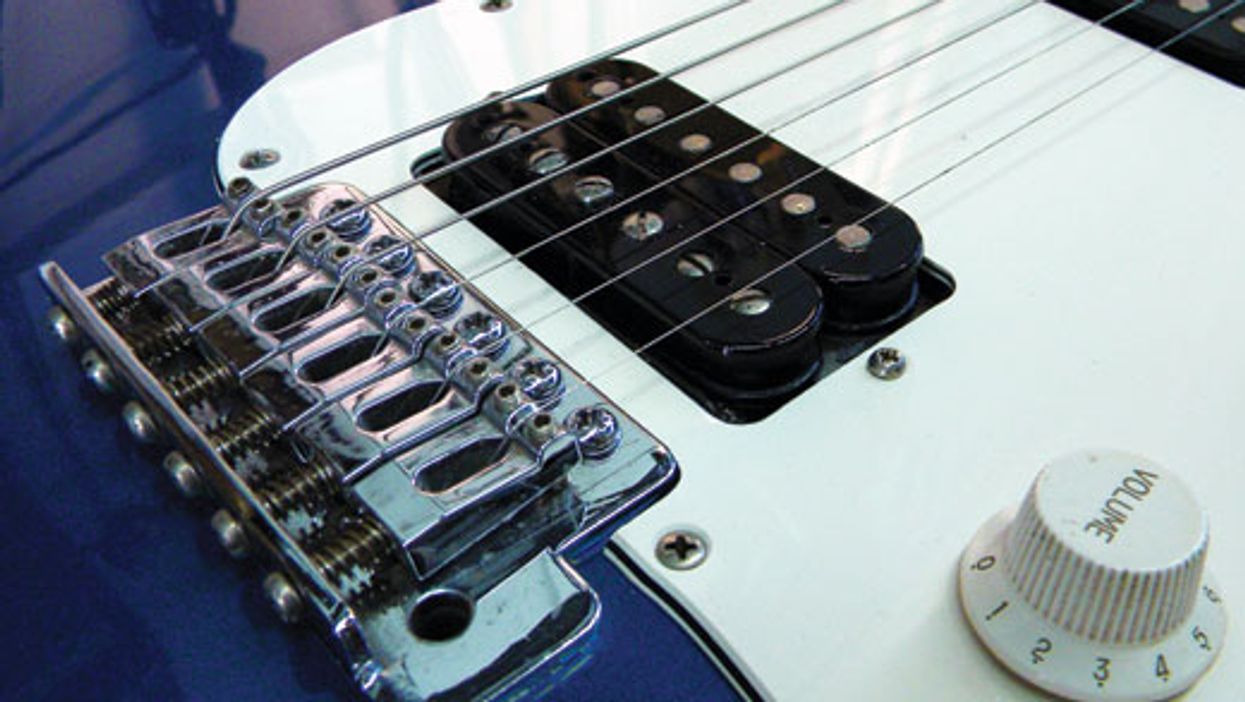
Guitar Shop 101 Guitar Shop 101: “Decking” a Stratocaster Trem It’s not for everyone, but locking down a Strat trem can resolve many tuning issues.John LeVanFeb 19, 2016
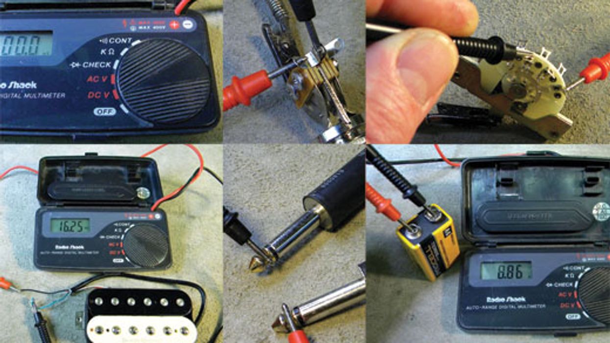
Gear Guitar Shop 101: Five Ways to Use a Digital Multimeter This handy tool can be a guitarist’s best friend.John LeVanJan 08, 2016
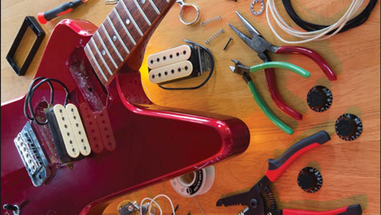
Pro-Advice Guitar Shop 101: Wiring Humbuckers in Parallel on an HH Strat Put some shimmer and spank into your dual-humbucker guitar with this alternative wiring scheme.John LeVanDec 11, 2015
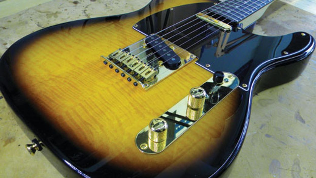
Pro-Advice Guitar Shop 101: Tips for Replacing a Tele-Style 3-Way Switch Got a funky blade switch on your T-style guitar? Here’s how to install a new one.John LeVanNov 06, 2015