The Leslie speaker was originally designed and voiced for the Hammond organ, and almost no Hammond organist worth his salt will be seen traveling or playing without one. We associate the sound of the Leslie with the Hammond so much that when plugging a guitar into a Leslie, a listening layman would most likely say, “Wow! Your guitar kinda sounds like an organ!” The frequencies of the speakers and the design of the cabinet were geared for the Hammond organ, so while plugging a guitar into it sounds really beautiful, it makes the guitar take on organ-like characteristics. This has been used to great effect by many guitarists throughout the years.
The Leslie appears on classic tracks by Jimi Hendrix, David Gilmour, Stevie Ray Vaughan, Jeff Beck, George Harrison, and countless others who used the seductive sounds of spinning speakers to add a unique touch to their tracks. Check out “Cold Shot” by Stevie Ray Vaughan, “Max’s Tune” by the Jeff Beck Group, and “Any Colour You Like” (Wembley 1974) by Pink Floyd for some excellent examples of rotary-speaker guitar tones.
Leslie speakers operate on a principal called the Doppler effect. This is a physical phenomenon that describes the change in frequency as an object changes position relative to a sound source. As a sound source gets closer to you, it will increase in pitch and volume, and the opposite will happen as it moves further away. The Leslie speaker operates on this principal on a relatively small scale, making the effect more subtle then a moving ambulance siren, but all the more beautiful. I always wondered if the Doppler effect could be applied specifically to the guitar. What would happen if a rotating speaker device was designed from the ground up for our 6-string weapon of choice? Could it maintain and embellish the frequencies of our instrument while giving that beautiful, room-filling, three-dimensional effect? Other than the vintage Fender Vibratone and scant offerings from Hammond-Suzuki and Motion Sound—some guitarists might also recall the elusive Mesa Boogie Revolver—nothing really scratched my itch. So, ever a believer in the DIY spirit, I decided to build one.
In approaching this project, my philosophy was to lighten and simplify the original Leslie design as much as possible, fine-tuning it to the guitar while maintaining a tight budget and not compromising on tone or function in any way. This was a tall order, and I had to rethink the Leslie design from square one. I came up with a simple 12" standard guitar speaker firing upward, with a rotating Styrofoam baffle mounted to a motor above it. The Styrofoam would have a sizeable chunk cut out of one of the sides, so the sound could only travel through the open part. The open part spins, therefore shooting the sound around and around to create the Doppler effect. To keep things simple, I decided to make this speaker cabinet passive, except for the power required to run the motor. So it operates like a basic 2x12 or 4x12 cab, and you can use your favorite guitar amp to power this little beast.
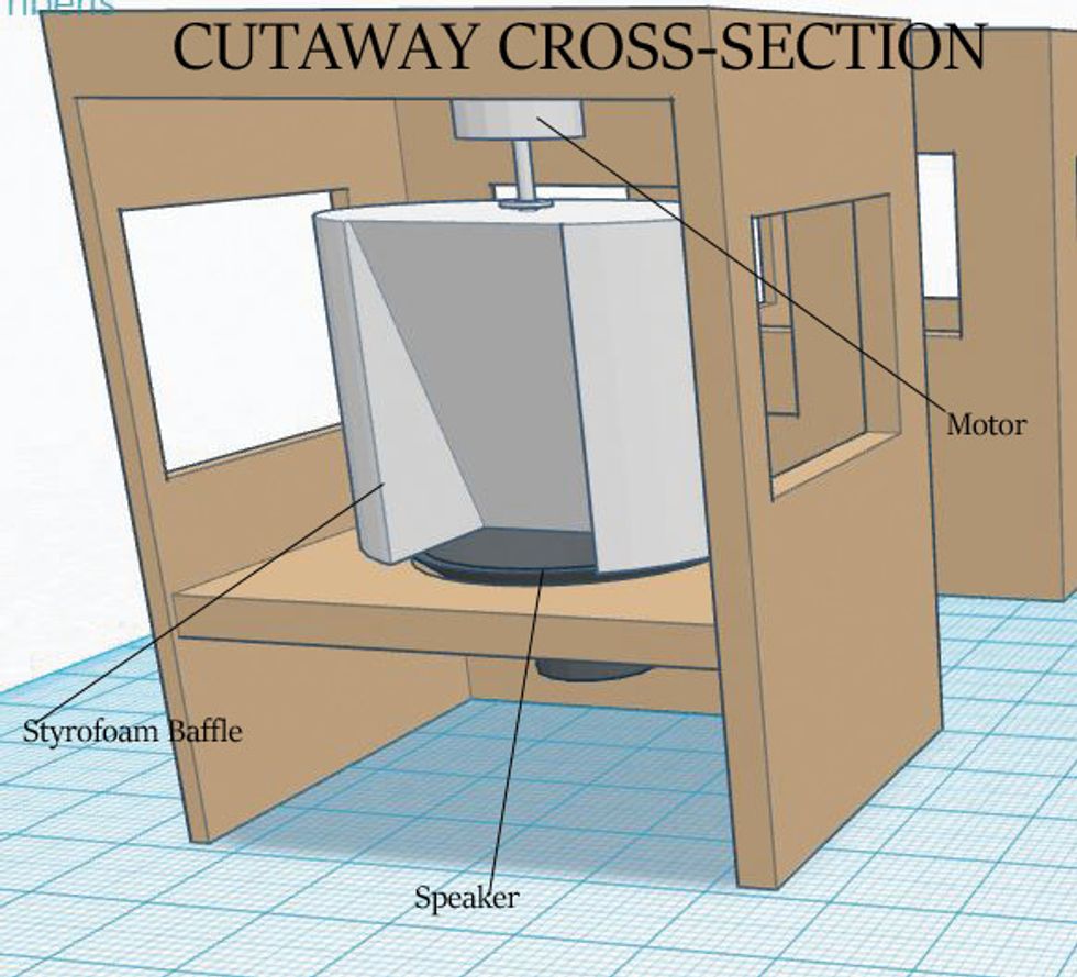
Fig. 1
Fig. 1 shows a CAD drawing of the cabinet. In this view, the removable rear panel is detached and we’re looking through the back of the cabinet. You can see the upward-firing speaker mounted on a board that’s permanently attached to three walls. The motor, which is fastened to the roof, rotates the Styrofoam cylinder that’s suspended above the speaker. As the cylinder spins, its cutaway pushes sound through “windows” cut into the three walls and rear panel. As the sound passes from one window to another, we hear the shifting tones created by the Doppler effect.
Okay—now that you have all your materials listed and collected, let’s get started! For this project, I enlisted the assistance of a professional woodworker to help build the cabinet while I directed him. (Special thanks to Robert and Monique at Woodworking Specialists in Tucson, Arizona, for helping me out and putting up with my incessant photography.)
Note: The wood I used for this cabinet is pre-finished furniture-grade 9-ply Baltic birch, so I did not need to finish the cabinet. If you are using non-finished wood, apply your favorite stain or finish before mounting any of the electronic components. Follow the instructions on the can to get the best results.
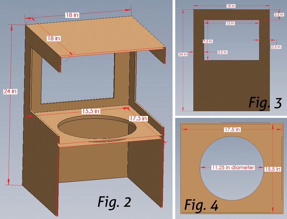
Before you start cutting any wood, study the following three drawings to get a visual sense of where we’re headed. Fig. 2 shows the cabinet dimensions, and Fig. 3 shows the measurement for the four window cutouts. Fig. 4 shows the speaker mount and its cutout; I’ll explain how I arrived at the speaker cutout measurements in a moment—its precise diameter depends on the speaker you’ve selected for this project.
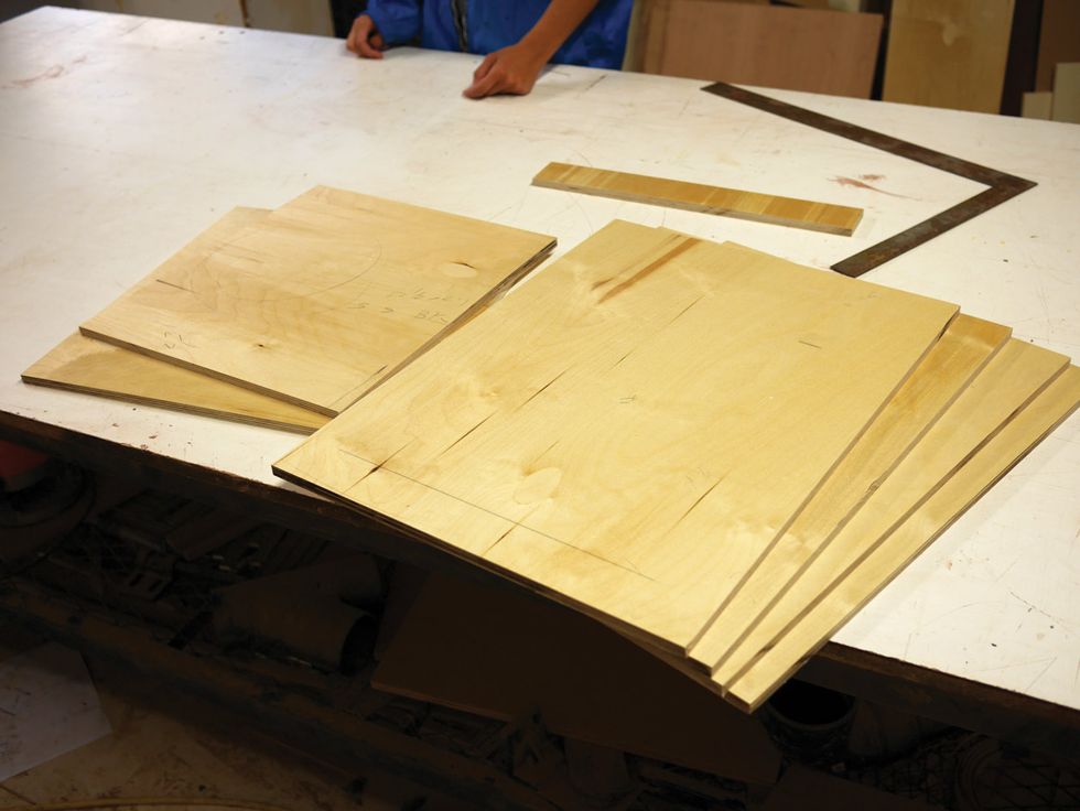
Fig. 5
Part 1: Assembling the Cabinet
Step 1. Start by measuring and cutting out the first three 24"x18" Baltic birch pieces—the cab’s front and sides—using a table saw or jigsaw. Make sure you follow the old woodworker’s creed: “Measure twice, cut once.”Step 2. Now measure and cut out the 24"x17" Baltic birch piece (the rear panel), followed by the 18"x18" roof and 17.5"x15.5" speaker mount.
When you’re done, you’ll have six pieces of wood that form the cabinet (Fig. 5).
Step 3. Now we need to cut matching windows into the front, sides, and removable rear panel. Use your table saw or jigsaw, and make sure to follow the measurements shown in Fig. 3.
Note: The 13"x9.5" window cutout is illustrated on one of our three 24"x18" pieces, and on these, the cutout is inset 2.5" from the top and sides. We want the identical 13" width for the window on the 24"x17" rear panel; this requires a 2" inset from the sides of that narrower rear panel. (The top inset remains 2.5".)
Fig. 6 shows the three matching front and side panels, and the rear panel (far left)—all with identical window cutouts.
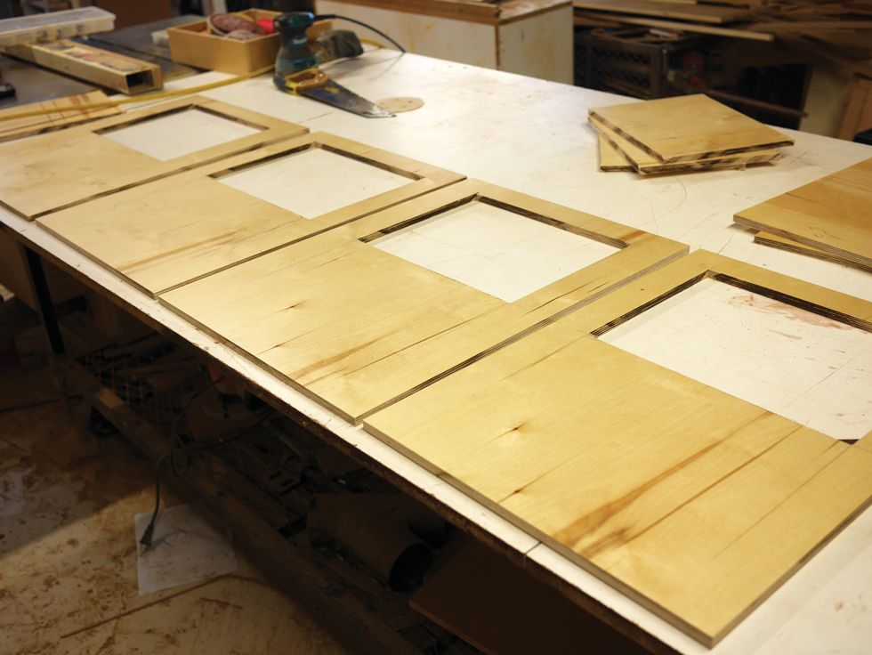
Fig. 6
Step 4. With your sander, work the edges of each panel until they are smooth to the touch. If you over-sawed a little on the windows, consider filling up the corners with wood putty so it looks neat.
Step 5. Grab the 17.5"x15.5" speaker board and find its center. Before you begin cutting, measure the flange of your 12" speaker and then subtract the flange measurement from 12. (In my case, the flange was 3/4", so I was left with 11 1/4" or 11.25" for the speaker cutout.)
Divide that number in half (5.625" or 5 5/8" for my speaker) and you have your radius. Using a compass, measure out that radius from the midpoint of the 17.5"x15.5" speaker mount, and then carefully draw a circle.
Step 6. Using a router or drill bit, drill a pilot hole near the edge of the circle. Then from that hole, carefully cut the circle with your jigsaw (Fig. 7). After that, sand the cutout edges smooth.
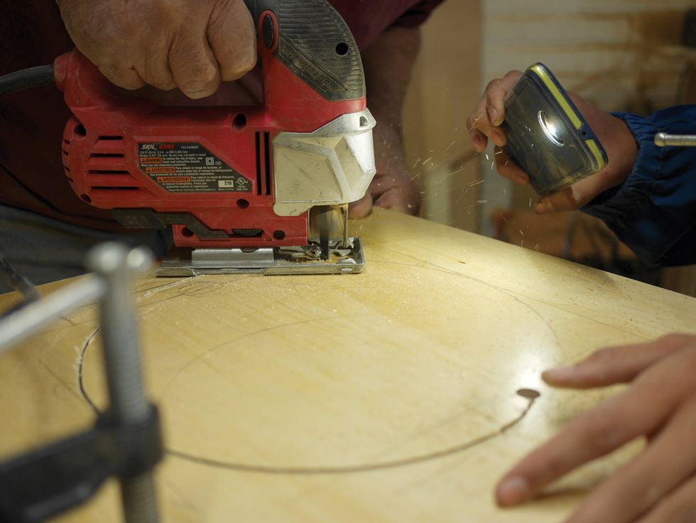
Fig. 7
Step 7. Now we’re going to attach the slats to support the speaker mount to the three 24"x18" pieces. Measure 2" down from the window of one of these pieces and apply a stripe or two of wood glue on the wall—not on the slat itself. Next, affix the slat to the wall (Fig. 8), making sure the slat is perfectly level.
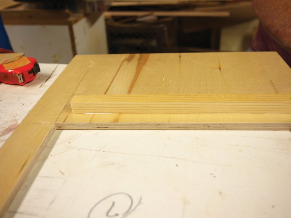
Fig. 8
Do this to all three 24"x18" pieces, and be sure to measure each slat’s location to confirm they’re identical. If you want extra strength, add four staples to each slat.

Fig. 9
Step 8. Once the glue has dried, it’s time to begin installing the speaker mount to the front and side walls. Take one of your 24"x18" pieces, place it upright, and put a stripe of glue on the top of the support slat (Fig. 9). This becomes the front of the cabinet.
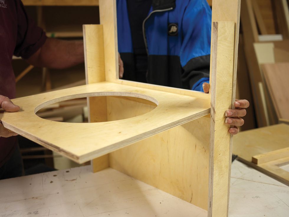
Fig. 10
Then place the 17.5"x15.5" speaker board on top of the support slat. To make sure the cabinet walls end up being flush with each other, take two pieces of scrap Baltic birch and place them on the sides while a friend holds the speaker mount and side piece together (Fig. 10). Let the glue dry enough that you can carefully lay the front wall on a flat surface with the speaker mount pointing up. Then let the glue dry on this perpendicular construction.
Step 9. Put a stripe of glue on the top of the speaker board support slat on your second 24"x18" piece. This becomes a side wall. Repeat this step for the third 24"x18" piece—the other side wall. While the glue is still wet on these two support slats, return to the front wall with its speaker board, and run a stripe of glue along the interior where the edge of each side wall will join the front (Fig. 11).
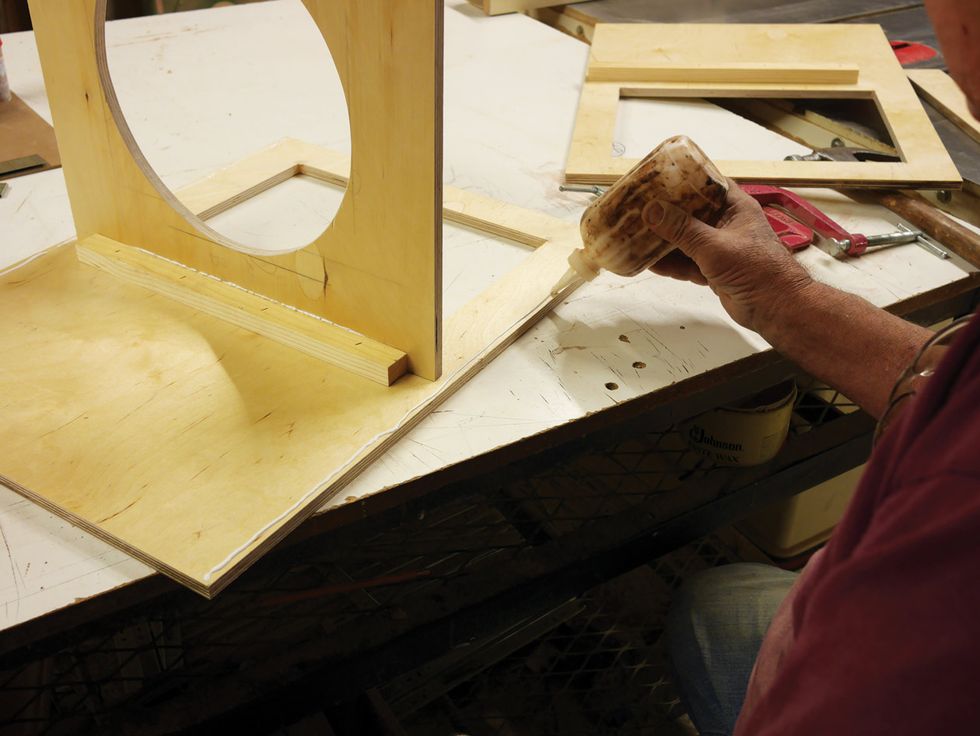
Fig. 11
Now clamp the side walls to the main wall, so you have three 24"x18" pieces joined together, as in Fig. 12. The speaker mount is glued to three support slats on the front and slides, and the front edge of each side is glued to the front wall. Wipe away any excess glue and let the frame dry.
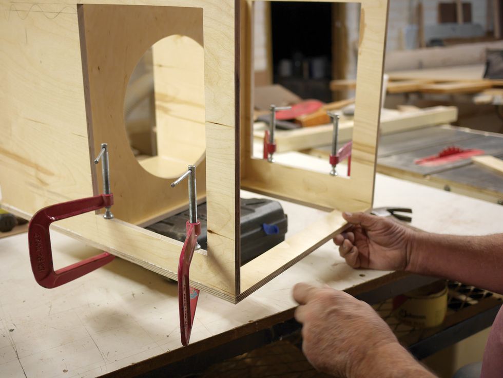
Fig. 12
Step 10. Now it’s time to install the support slats for the removable rear panel. Turn the box on its side, measure 1/2" (or the thickness of your wood) in from the edge of the open back, and then glue one of the 15" rear panel slats onto the side wall, as shown in Fig. 13. When the glue is sufficiently dry, turn the box over on its other side and repeat this process, making sure both slats are positioned identically. Let the glue fully dry on these rear panel support slats.
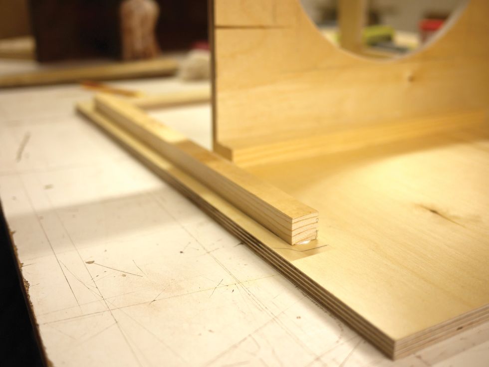
Fig. 13
Step 11. Though we won’t attach the removable rear panel or roof quite yet, this is a good time to go over the edges of the roof and box corners with sandpaper or a sander. Stand the box up, press the rear panel up against its support slats, position the 18"x18" roof on top, and smooth out any rough edges (Fig. 14). Do a loose “test fit” to make sure everything squares up. Congrats—we now have a 24" tall box with four sides—the front and sides are permanently glued together and the rear panel is currently unattached.
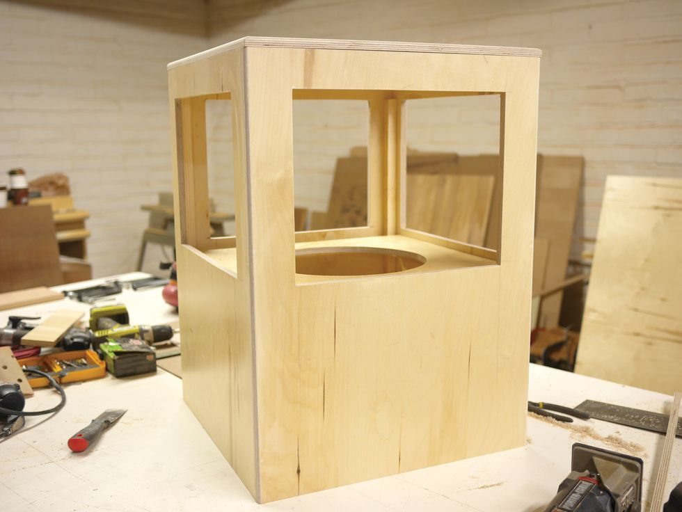
Fig. 14
Step 12. This is a good time to drill pilot holes for the wood screws that will ultimately secure the removable rear panel to the side walls. The screws will run vertically along the very back of the side walls, passing through them to penetrate the left and right edges of the rear panel.
With the box standing up on your workbench, pick a side, and pencil in marks for three screw holes. At 1/4" in from the side’s back edge (or one half the thickness of the rear panel), make three marks at 6" intervals (6", 12", and 18"). Repeat this on the other side, and then drill your pilot holes.
Part 2: Installing the Speaker
Step 13. After the glue holding your box together has dried and cured (this can take anywhere from 24 to 72 hours, depending on your glue), you can now install the speaker. Place your speaker in the hole and screw it into the mount.Step 14. Once the speaker is screwed in, test it to make sure it works. Using copper alligator clips, attach some speaker wire to the speaker terminals and a mono jack. Grab a speaker cable, and plug in any old guitar amp with a speaker output rated for your speaker, turn on the amp, and strum a few chords. If things sound right, it’s time to move on.
Part 3: Building the Motor Assembly
Step 15. Now we cut a hole in the Styrofoam baffle (Fig. 15). If you are using a hot knife, be sure to work in a well-ventilated area. If you don’t have a hot knife, a good utility knife or hacksaw will work too. The width and depth of the hole will affect how the Doppler effect sounds in your rotary cabinet. To ensure burly shifting tones, I cut a medium-sized hole that was both deep and high.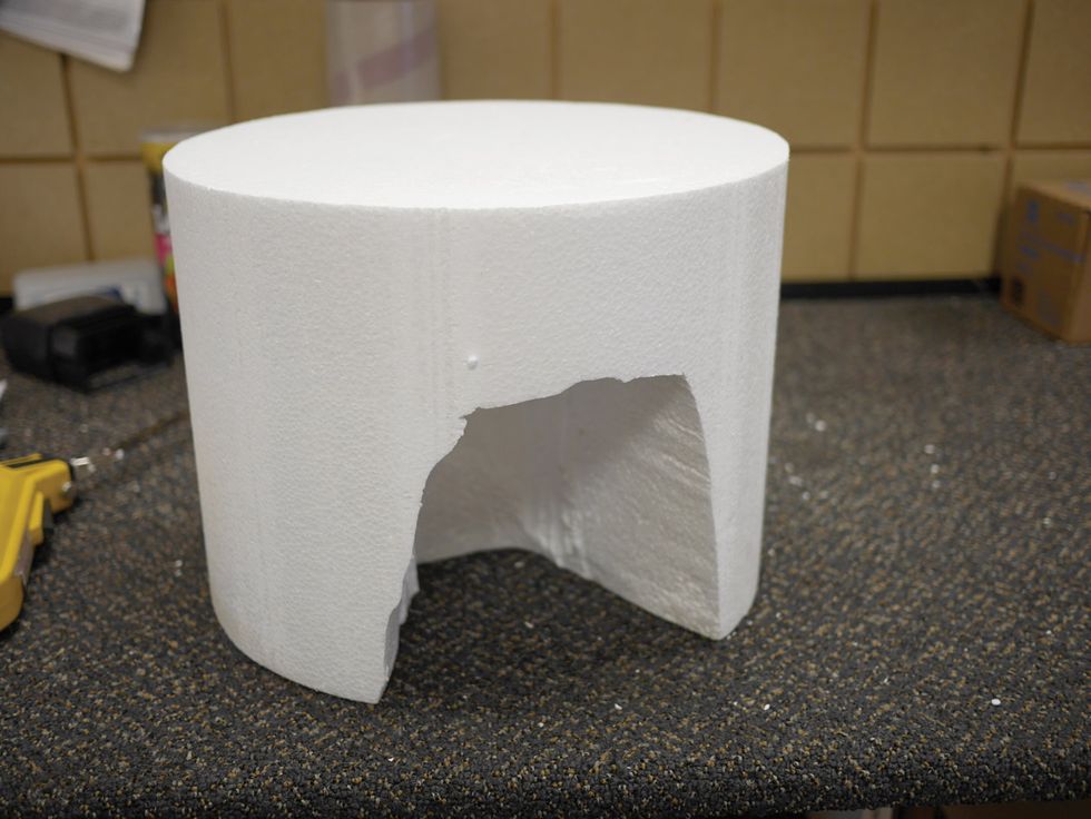
Fig. 15
Step 16. Now it’s time to mount the motor. On your 18"x18" piece of Baltic birch—the roof— create an “X” using a straight edge and pencil. Place the straight edge across diagonal corners, draw a line, and then repeat the process with the other two corners.
Place your motor with the mounting hardware in the middle of the “X,” and then verify it’s in the precise middle by making sure each side of the motor is equidistant from the edge. Finally, mark the mounting holes with a pencil.
Step 17. Find a drill bit that’s slightly smaller than the mounting hardware screws, drill through the marked holes from top to bottom, and then screw in the mounting hardware. Once all three screws are in, flip the roof over so the threads are facing up towards you. Put your motor on the screws and make sure each screw goes through each mounting hole. Drop a washer, nut, and lock washer (in that order) that fits your mounting hardware onto each screw (Fig. 16).
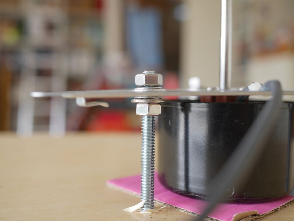
Fig. 16
Step 18. Now verify that the motor is level by placing your leveling tool on top of it as best you can. After you’ve tightened the mounting screws, check again with your leveler to make sure you didn’t bend anything out of shape.
Step 19. Now comes one of the most important steps in the entire assembly—making sure you properly mount the baffle. If the Styrofoam is not mounted exactly in the center, at higher speeds it will wobble all over the place and shake the entire cabinet. Take plenty of time and be very calculated in your approach. To find the center, use the “chord” method. There’s an excellent tutorial for this on YouTube called “How to Find the Center of a Circle” by Tomahawk DIY.
Step 20. Once you’ve found the baffle’s center point, drill the hole for the motor shaft. Find a bit that’s a few sizes smaller than the shaft, so when it comes time to mount the baffle, it’ll fit snugly. Drill into the midpoint of the Styrofoam baffle.
Step 21. Take your scrap wood and find its center. If you can, I recommend using a circular piece since that’ll help with rotary balance. If it’s a circle, find the midpoint on the piece of wood by repeating Step 19, and if it’s a square piece, find the midpoint by repeating Step 16.
Glue the wood piece to the Styrofoam (Fig. 17). Using a nail or some other rod-like object that loosely fits in the wood piece’s hole, probe around very lightly until you find the hole you drilled in the Styrofoam. Once you locate it, let the nail stay there for a short while to prevent the glue from leaking and drying in either hole. Pull the nail out after about 10 minutes and confirm there’s no glue inside the holes. Let the glue dry for 24 to 48 hours.
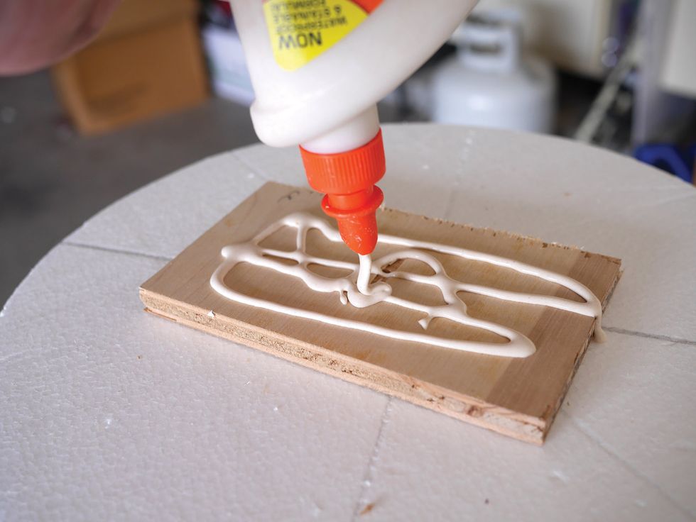
Fig. 17
Step 22. After your baffle has had time to dry, mount it onto your motor shaft (Fig. 18). Make sure it’s as straight as possible by using your leveling tool. Remember, the amount of clearance or space between your baffle and speaker will alter the intensity of the effect. I placed my baffle fairly close to the speaker.
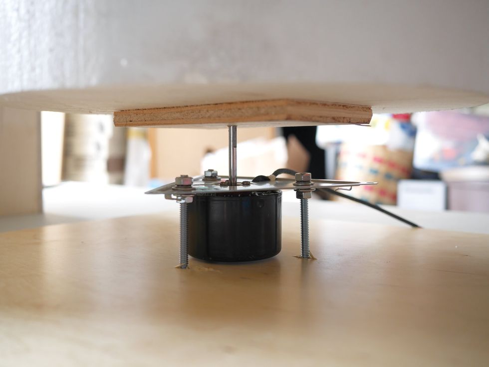
Fig. 18
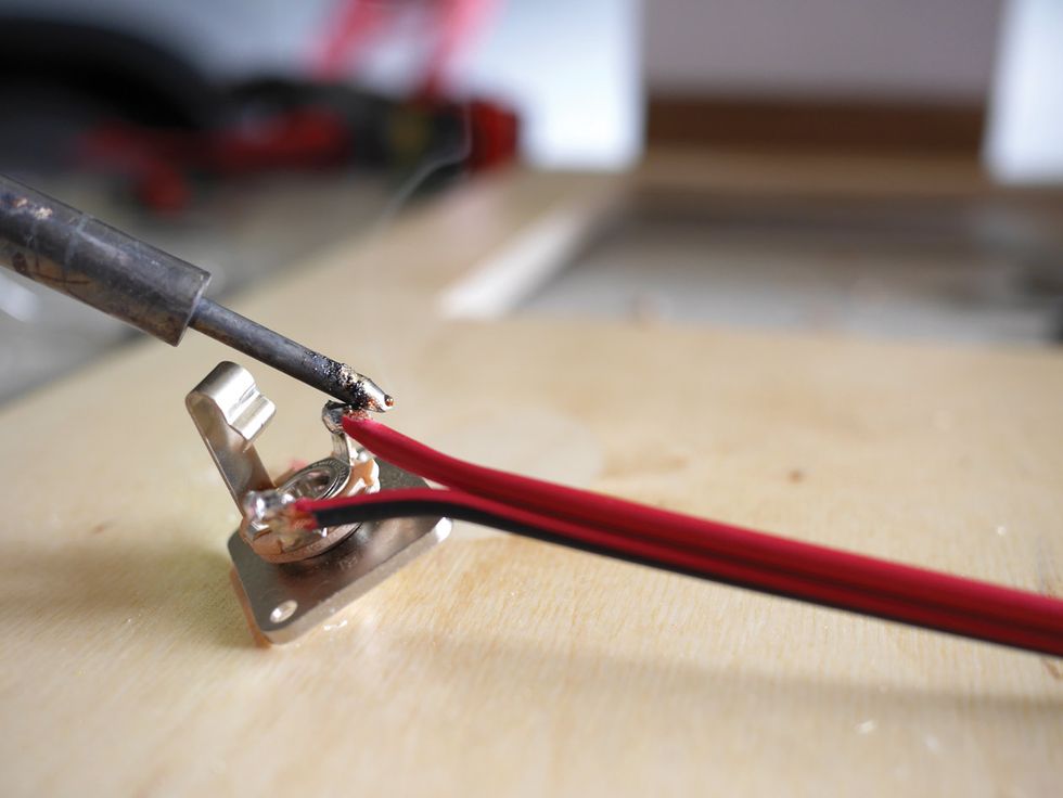
Fig. 19
Part 4: Electronics and Finishing Touches
Step 23. In the 24"x17" rear panel, drill a hole just large enough for the speaker jack.Step 24. Before you attach the jack, measure out a 3' length of wire. Solder the positive to the tip and the negative to the sleeve (Fig. 19). Now mount the jack. If you position it above the plane of the speaker board, also drill a 1/4" hole in the board so the speaker wires can snake up through it.
Note: If soldering is a challenge, read “Soldering 101: A Step-by-Step Guide” in the November 2014 issue of Premier Guitar, which can be found at premierguitar.com.
Step 25. Now we need to give the motor power. Cut another length of wire, keeping in mind this will need to run from the top of the enclosure where the motor is all the way down to where the power will be. I cut mine to 5 1/2', because I like to have a lot of wiggle room to work with. Strip the wires and solder them to the motor. Use heat shrink or electrical tape to prevent the positive and negative wires from making an unwanted connection. Then, using your staple gun, staple the wire taut all the way to the edge of the roof so your baffle doesn’t hit it when it spins (Fig. 20).
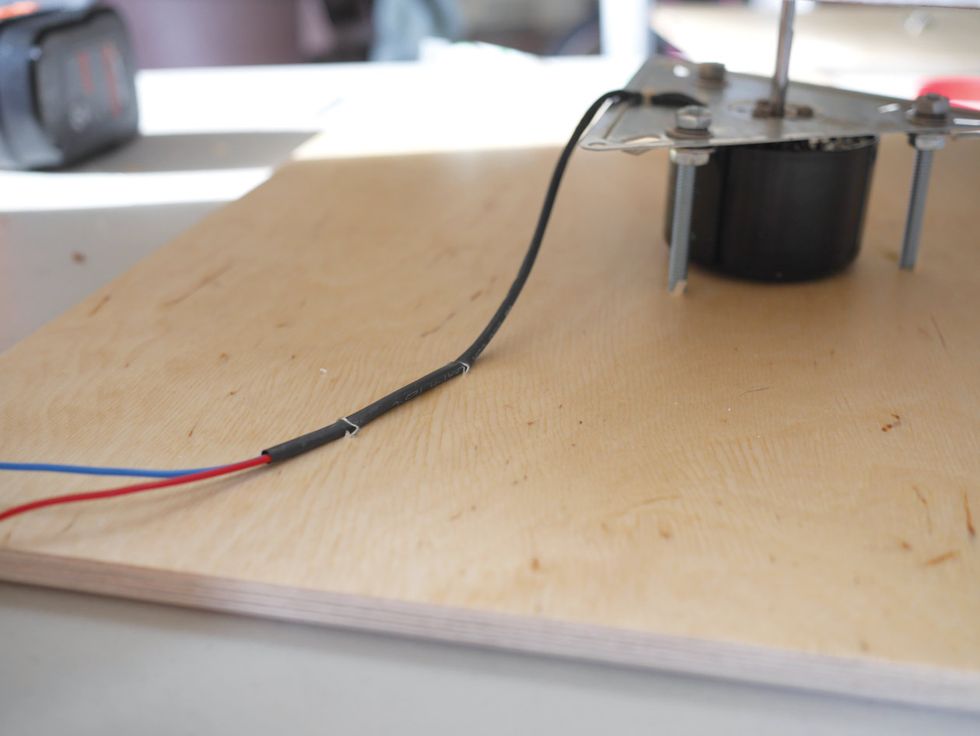
Fig. 20
Step 26. Once you finish stapling, it’s time to install the IEC power jack. Measure its dimensions, then cut a matching hole in the rear panel using your jigsaw. After checking that it fits flush onto the door, mount it to the rear panel.
Step 27. To wire the IEC jack, cut off the receptacle side of your 3' or 6' extension cord, and then separate the two wires and strip them. AC current has no polarity, so it doesn’t matter which wire you solder to which terminal, as long as it’s the upper two terminals, as shown in Fig. 21. Solder the wires to the terminals.
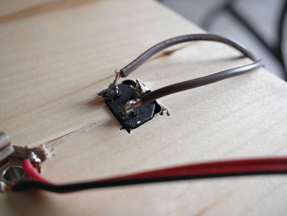
Fig. 21
Step 28. To cut the grille cloth, measure the length and width of your windows. Take note of that measurement, and then add an inch or so to both numbers, since you want a bit of overhang. Cut it to size with a utility knife—one piece for each wall, four in total (Fig. 22).
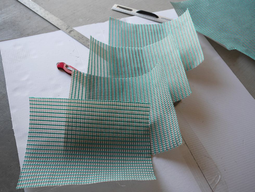
Fig. 22
Step 29. Pull the cloth taut over each window and staple the corners (Fig. 23), making sure the fabric is tight.
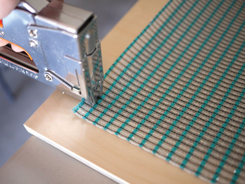
Fig. 23
Step 30. Slip the baffle off the motor shaft and put it aside. Place the roof on top of the box and staple the dangling motor wires to the nearest side wall. Make sure they’re far out of the way of the rotor baffle, and then push the baffle back onto the motor shaft.
Step 31. Position the rear panel and screw it to the sides. Screw the four 3-leg metal corners around the top, as in Fig. 24. These 3-leg corners secure the top to the cabinet walls. Now screw the four lipped metal corners to the bottom of the cabinet, and then add rubber amp feet (optional).
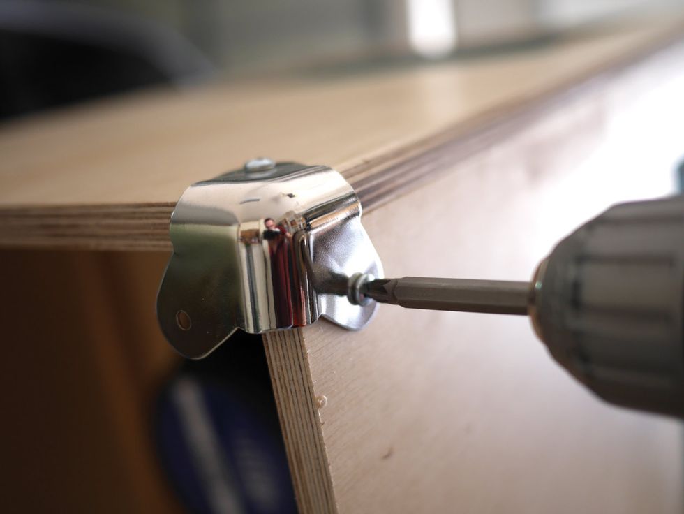
Fig. 24
Step 32. Now it’s time to hook up your electronics, following the easy wiring diagram in Fig. 25. The red line represents the positive and the black line represents the negative wires of both the motor and power supply. Once you’ve wired everything up, you can organize the power supply and wires any way you like inside the cab—just keep everything clear of the rotating baffle.
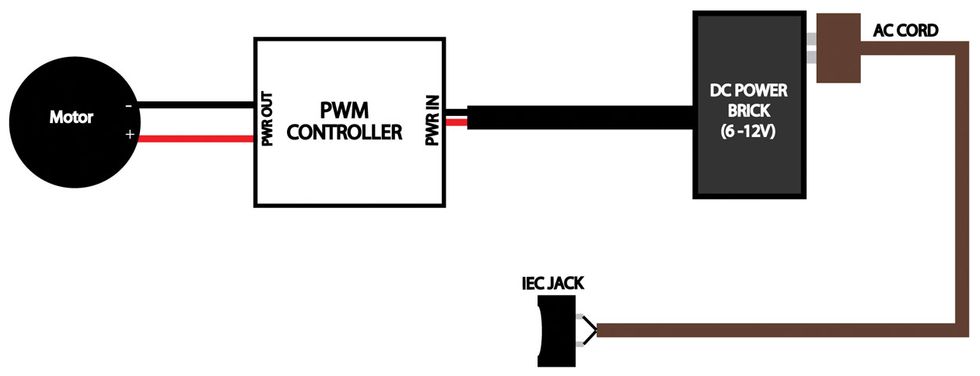
Fig. 25
Step 33. If your PWM controller came with a speed control pot, test it to make sure it works, drill a hole in the front of the cabinet, push the pot through, and mount it.
Step 34. Now find your handle, center it, and screw it into place. Make sure you bend it upwards slightly before installing it, so your hand will have room to grab it.
Just like that, you have now finished your very own rotary speaker cabinet! Plug it into your favorite amp’s speaker output, and then plug in the IEC power cable. Turn on the unit, set the speed where you like it, and fire away!
Author Yoel Kreisler welcomes questions or feedback about this project. You can reach him at YKreislerPG@gmail.com.
Sound Judgment
If you’ve trudged through this wilderness of wood, wires, speakers, and Styrofoam, you’ve come to the final and most critical question: How does this DIY rotary speaker sound? I recorded two stereo clips, so I’ll let you be the judge of that.These are the signal paths for both samples. The clean sample is a Strat loaded with David Allen Echoes pickups plugged into a Ceriatone OTS Mini 20, and an Origin Effects Cali76 Compact Deluxe compressor into the DIY cab. The dirty sample is the same Strat loaded with Echoes, the Ceriatone OTS Mini 20, and a Gurus Amps SexyDrive MkII into the DIY cab.