Is there a 15-year-old out there who’s never dreamed of having a time machine—a hi-tech contraption that’d take you back in time 10 minutes to avoid the botched joke that ruined your chances with so-and-so, or maybe to think twice about that failed guitar twirl that obliterated mom’s favorite lamp? Or, even better, beam you into the future, Biff Tannen-style, so you can ferret-out bankable sports bets—or just skip the rest of high school altogether! It’s a silly fantasy, yet one we never completely outgrow over the post-teen decades.
The funny thing is, in a sense, time machines have existed since the early 1970s. They may not have had all the bells and whistles we dream of, they may not have come with a clever talking dog who explained all the new sci-fi awesomeness for us—and heck, they didn’t even take you into the future—but they still existed in the form of delay/echo units. The first such “time machines,” at least in terms of mainstream availability and affordability, came out back during the bell-bottom decade—and they were powered by another hyphenated double-B technology: “bucket-brigade” chips.
If you’ve been playing guitar for a while, you’ve no doubt heard a lot of hoodoo and voodoo about expensive vintage bucket-brigade effects pedals and processors over the years, but even players with fewer axe-wielding years under their belts have likely seen and heard a fair amount about devices powered by modern renditions of this once-dead, now-resurrected circuitry. Which is why we’re offering this handy-dandy guide to help you understand bucket-brigade devices (BBDs) from then and now.
So What Exactly Are BBDs?
Bucket-brigade devices were the first wholly electronic devices for producing time-delay of electronic signals. Prior to their development, most effects that time-staggered an audio signal relied on magnetic tape and manipulation of tape speed. (Examples include the various iterations of the Echoplex and Roland’s Space Echo.) BBDs permitted easier production of echo and effects like flanging, chorus, and double-tracking from a much smaller device. Further, BBD effectors enabled flanging to be produced onstage without the prior need for two tape decks, and rotary-speaker-like effects were possible without lugging around a massive Leslie setup.
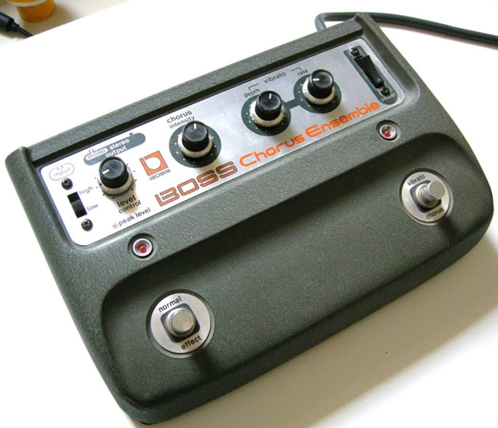
The original Boss CE-1 Chorus Ensemble was a classic early BBD-driven chorus stompbox.
Photo courtesy of Spaghetti Vintage
Between the late 1970s and mid 1980s, many classic BBD-based effects were issued, including the Boss CE-1 Chorus Ensemble and CE-2 Chorus; flangers like those from Electro-Harmonix, A/DA, and MXR; and delays like the Electro-Harmonix Deluxe Memory Man and Boss DM-2—not to mention desktop and rackmount delays and multi-effectors like the Ibanez AD-230 and MXR Flanger/Doubler. BBDs would also find their way into synthesizers, mixers, and even karaoke machines. Eventually, many of these effects—particularly the delays—would become replaced by digital units, largely because of the latter’s greater delay capacity. But the demise of original BBD effects was also due to the fact that the principal manufacturers—Matsushita (now known as Panasonic), Reticon, and Philips Research Laboratories—eventually ceased production. Even so, musicians’ affection for analog BBDs never really went away.
But MXR’s Flanger/Doubler was an BBD processor found in studios during the early ’80s.
Photo courtesy of Vintage and Rare/Soundgas
Despite the fact that both entry-level and high-end digital multi-effect units became all the rage during the ’80s (with players like U2’s the Edge, Steve Vai, and Eddie Van Halen becoming notorious for their “refrigerator stacks” full of rackmounted digital gear), a small segment of devoted players never gave up on the “warm,” classic sound of analog gear. As the 1990s wore on, new boutique pedals powered by new-old-stock (NOS) BBD components (for example, Moogerfooger’s MF-104M Analog Delay) started to build the buzz anew—although at a premium price, and often in very limited runs. Beginning slowly in the early 2000s, and picking up the pace considerably in 2015, a new generation of much more affordable BBD-driven pedals has been made possible thanks to companies like Coolaudio, Belling, and Xvive Audio producing accurate replicas of original BBD chips.
Much like classic 3-tube amplifiers of yore—amps like the Fender Champ, with its basic preamp-tube, power-tube, and rectifier-tube circuit—there are common design aspects and considerations for nearly all effects that use BBDs. So let’s take a closer look at the nuts and bolts of how these magical chips work and how they’re used.
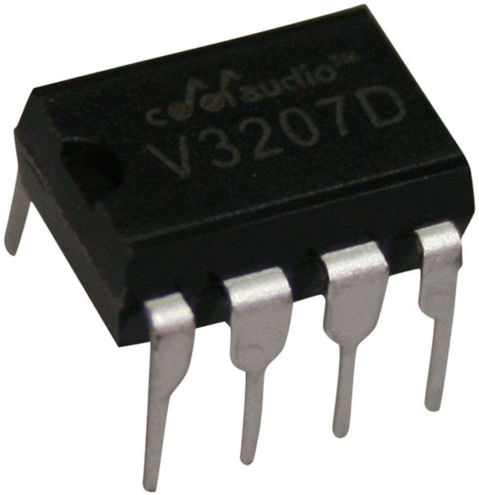
Manufacturers such as Coolaudio (whose new 1024-stage V3207 BBD is shown here), Xvive, and Belling are now manufacturing accurate replicas of classic analog chips of yore.
Would You Care to Try a Sample?
BBDs—or analog shift registers, as they are properly called (or sometimes charge-coupled devices)—were first developed in 1969 as integrated-circuit (IC) chips containing a large number of storage cells (tiny capacitors, actually) and switching transistors. The “register” part of a BBD chip is capable of holding a sampled voltage (i.e., the “analog” part) and passing (or “shifting”) those sampled voltages along in a first-in, first-out fashion. Like a film that creates the illusion of continuous motion using 24 frames per second, BBDs create the illusion of continuous sound by capturing and spitting out samples. The sampled voltages (or sounds) can seem to occur more slowly by setting the device to spit them out slower than they came in, or by simply holding onto them for a wee bit. Because the innards of these IC chips acquire and pass along the samples continuously, from input to output, in a manner similar to a line of firefighters passing along buckets of water from one to the other, they are referred to as “bucket brigade” devices. And just as with motion pictures, the more samples (or frames, in the case of a film) taken in within a set period of time, the smoother the apparent transition between samples.
When most people hear the word “sample” in a context such as this, they immediately think of digital samples. How are analog BBD samples different from digital samples? In a number of ways. First, they aren’t transformed or encoded, as digital signals must be. They are a literal snapshot of whatever the signal voltage is at the moment the snapshot is taken. One could argue that analog BBD devices have infinite resolution, because unlike with the analog-to-digital (and then digital-to-analog) conversion required in digital processors, there’s no rounding off of signal information to the nearest coded value. In fact, back in the early digital days when the best signal resolution one could hope for was 12-bit resolution, the analog sampling of a BBD circuit made for higher audio fidelity. With 24-bit digital encoding being common these days, the difference in audio quality between an encoded digital snapshot, and a literal analog snapshot, is largely unnoticeable to most players.
A second way in which analog samples are different from digital samples is that, unlike digital code’s ability to be retained in memory for as long as one wishes, analog samples have a limited lifespan. The capacitors storing them leak, so each sample has to get moved along to the output quickly enough. Otherwise there won’t be much left in the “bucket” to pass along. At the exact moment a sample is taken, it may have been 250 millivolts (mV), but eventually declines to 247 mV, then 243 mV, etc., if it’s not passed along right away. This signal loss is less of a problem when the delays are very short and the samples get passed along quickly, as in flanging. But when samples get passed along very slowly (for example, to achieve a long echo), they pass through all those leaky stages again and again for additional repeats. If you set an analog delay to its maximum delay setting, you can often hear a substantial loss in fidelity. Given this reality, it goes without saying that no matter how much you may like analog delays, the very idea of an analog looper pedal is a nonstarter.
Another thing to remember is that the sample that gets passed along is a snapshot of something that already happened. It may not have happened very long ago, but it still already happened. So, while BBDs can almost catch up to real time in some instances, in general they will always lag behind by some small amount of time. The various musical applications of BBD chips vary how much they lag, and how closely they nearly catch up to a nondelayed version of the signal.
The more Legos you use, the more realistic-looking your sculpture. Same goes for audio sampling.
Photo by Shawn Hammond
Year after year, a group of local enthusiasts shows off fantastic dioramas made entirely out of Lego bricks at the annual Maker Faire in my area. One of the things I’m always struck by is that the realism of the construction depends on how many bricks are used to make it—the more bricks there are, the more nuance there is in the final image. The same is true of audio sampling. Basic depiction of a sound at any given frequency can be accomplished with two samples: one representing the positive half-cycle of the sound wave, and one representing the negative half-cycle. But that turns the signal into a series of square waves, and does that really convey the complexities of the original, or are we building something with two bricks that really needs many more to look and sound like the real thing? A sound wave might have a gradual ascent and descent, so describing it as one step up and another step down just doesn’t cut it.
The general principle with digital audio sampling is that the sample rate should be three to four times the highest frequency to be reproduced, if not more. So, if a signal processor is intended to process and output a signal whose content goes as high as 5 kHz, it should not sample the audio signal fewer than 20,000 times per second (20 kHz). That will do a bare-bones job of accurately representing a 5 kHz signal, and a better job at representing lower frequencies. At a 20 kHz sampling rate, a single cycle of a 1 kHz signal would be portrayed with 20 samples—better than four, but still somewhat block-y and definitely not hi-fi. Think Commodore 64 graphics rather than 1080p.
Considering this, the amount of delay time one can expect to get out of a BBD depends on how wide a bandwidth you want to reproduce with it. If you want more frequency content to be included in the time-shifted signal, you’ll need to sample more of the signal and do it faster. But the trade-off is that, even though sampling faster yields better sound quality, it also yields less time from the BBD. Which brings us to….
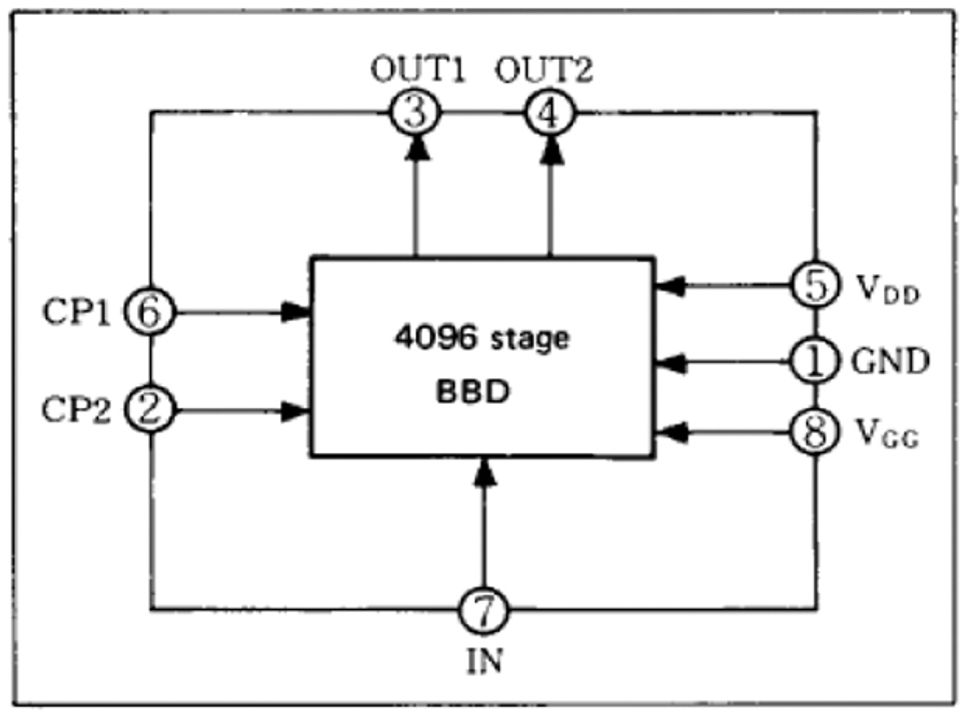
Fig. 1 — In this pin diagram for a Matsushita MN3005 BBD chip, pin 7 is where the signal enters the chip, pins 3 and 4 are the output, and 6 and 2 are the tick and tock pins.
Just as a movie projector and tape recorder require a motor to pour out their content, a BBD requires something to move the samples along. That something is a clock that puts out a complementary tick and tock to pins on the BBD chip at varying speeds, which in turn help dictate the fidelity and bandwidth of the signal. Internally, the chips themselves are essentially divided up into two parallel sets of stages—two lines of little people passing buckets, if you will. And just as with a real bucket brigade made up of people passing pails of water, each pin in the BBD can hand off or take a bucket—but it can’t do both at once. Consequently, the two parallel sets of stages take turns. When the clock ticks, one set of stages is passing off a sample to the next stage in line, and the other set of stages is receiving a sample. When the clock goes tock, the reverse happens. The two paths work in complementary manner so that there is always one sample available in interleaved fashion, each arriving at a separate output pin. Fig. 1 is a pin-out diagram of a Matsushita MN3005, the chip used in many analog delays from the late ’70s to the early ’80s. As you can see, there is only one input pin (7) but two output pins (3 and 4). The tick and tock pins are 6 and 2.
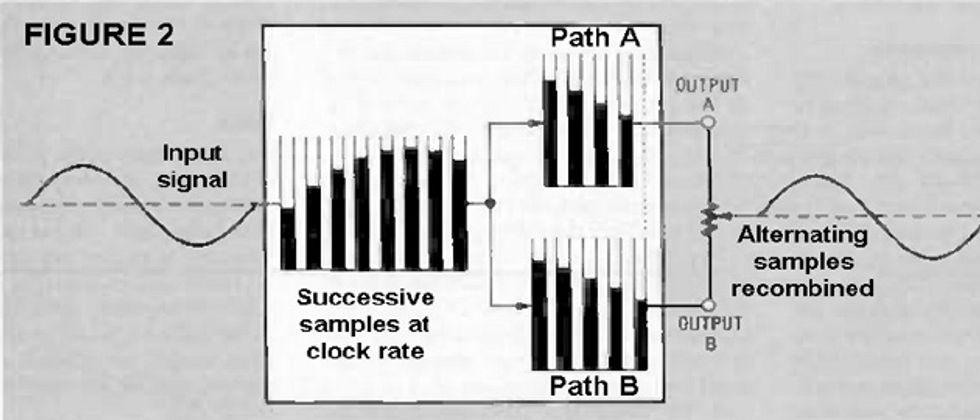
When these alternating interleaved samples reach the output of their respective path, they are combined to provide a continuous, seamless stream of samples (see Fig. 2). Some pedals (such as the Boss BF-2 Flanger) simply link the two output pins together directly, while others (like Electro-Harmonix’s Deluxe Electric Mistress) use a pair of equal-value resistors to electronically mix the two paths together. Still others (like the old A/DA Flanger) use a trimpot to perfectly balance the two outputs. In the latter example, not only does the more precise balancing yield a more faithful representation of the input signal, but it also serves to better cancel out artifactual noise from the clock—kind of like a humbucker in a chip!
Fig. 2 — The input signal is sampled, with a tick and tock from the BBD’s clock assigning each sample to its respective path. The alternating samples are interpolated and “stitched” together at the output.
How Much Time You Got?
Many tube-amp fans can calculate roughly how much power an amp will deliver based on the number and types of output tubes it uses. For example, we don’t expect more than 5 to 10 watts from a single-ended amp using one power tube, 12 to 25 watts from a pair of 6V6GT tubes, and so on. Similarly, we wouldn’t expect a builder to design a 100-watt amp based on a dozen EL84s, because a quartet of EL34 will yield that kind of power in a smaller, more affordable, easier-to-maintain package.
Similarly, BBDs come in different capacities, as indicated by the number of stages they have. Just as with power tubes, stages can be coaxed to yield a little more or a little less, depending on the rest of the circuit. For audio purposes, BBDs begin at 256 stages, with each unit higher in the series generally doubling in capacity: 512, 1,024, 2,048, and 4,096 stages. The latter is the largest capacity available on a single chip.
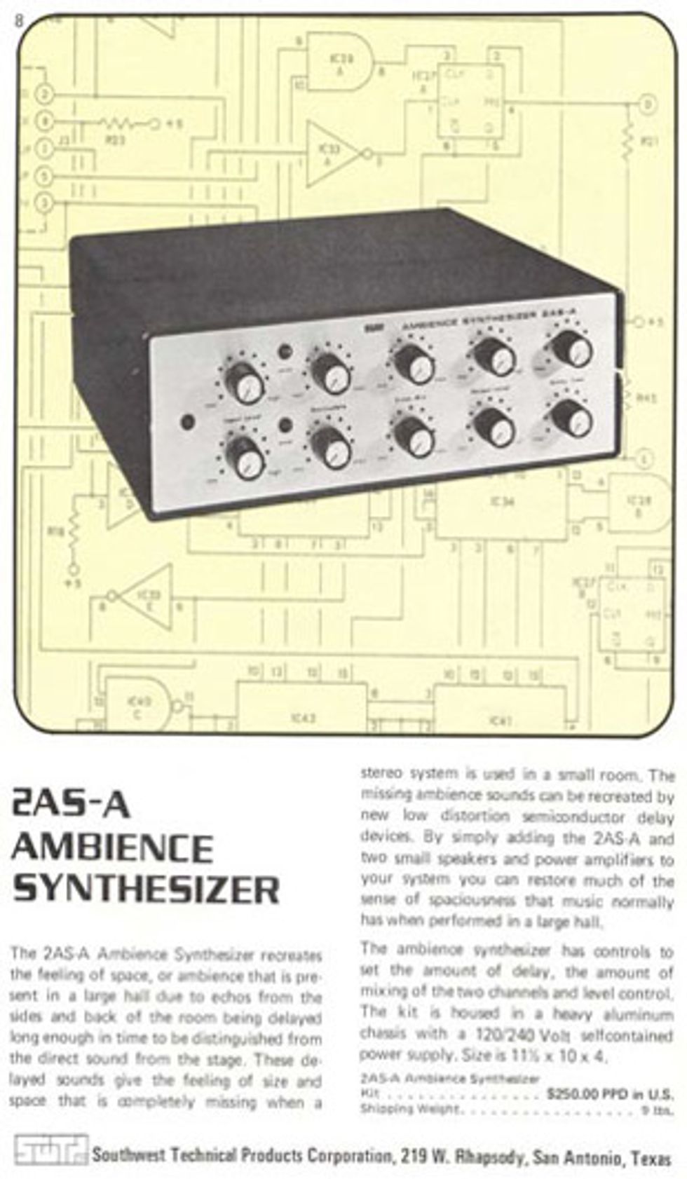
A vintage ad for SWTPC’s Ambience Synthesizer, which used three 1,024-stage BBDs in series.
The maximum time delay available from any single BBD is a joint function of the number of stages, the clock (i.e., sampling rate), and the desired bandwidth. So, a 1,024-stage chip can provide twice as much delay time as a 512-stage chip if it runs at the same clock rate, and the same amount of delay if clocked twice as fast in order to give the signal a little more bandwidth and fidelity. It works the same in reverse: An effect designer could squeeze a full second out of a 4,096-stage BBD chip (which is normally not used for more than maybe 350–400 milliseconds), but doing so would require a very slow clock rate—which would seriously limit bandwidth and fidelity. (It would sound like something happening in the apartment next door, and lose considerable fidelity after two or three repeats through the chip.) The old Boss DM-1 used a now out-of-production Reticon chip with 2,000 stages and claimed a maximum delay time of 500 ms, but at that delay setting there was a steep roll-off of the signal above 1 kHz. The next Boss analog delay, the DM-2, used a 4,096-stage chip to generate a maximum delay time of 300 ms at greater bandwidth.
Cascading multiple BBDs yields the sum of their individual delays—although each handoff between BBDs does pose small possible risks to audio quality. But careful circuit design can mitigate these risks. There have been some interesting products over the years that used this cascading BBD approach. Before 4,096-stage units became available, the earliest EHX Deluxe Memory Man pedals, as well as the MXR Analog Delay and the Southwest Technology Products Corporation (SWTPC) Ambience Synthesizer, used a trio of 1,024-stage chips in series. More recently (but still before 4,096-stage chips were back in production), Electro-Harmonix used four 2,048-stage Panasonic MN3008 chips for its Deluxe Memory Man reissue.
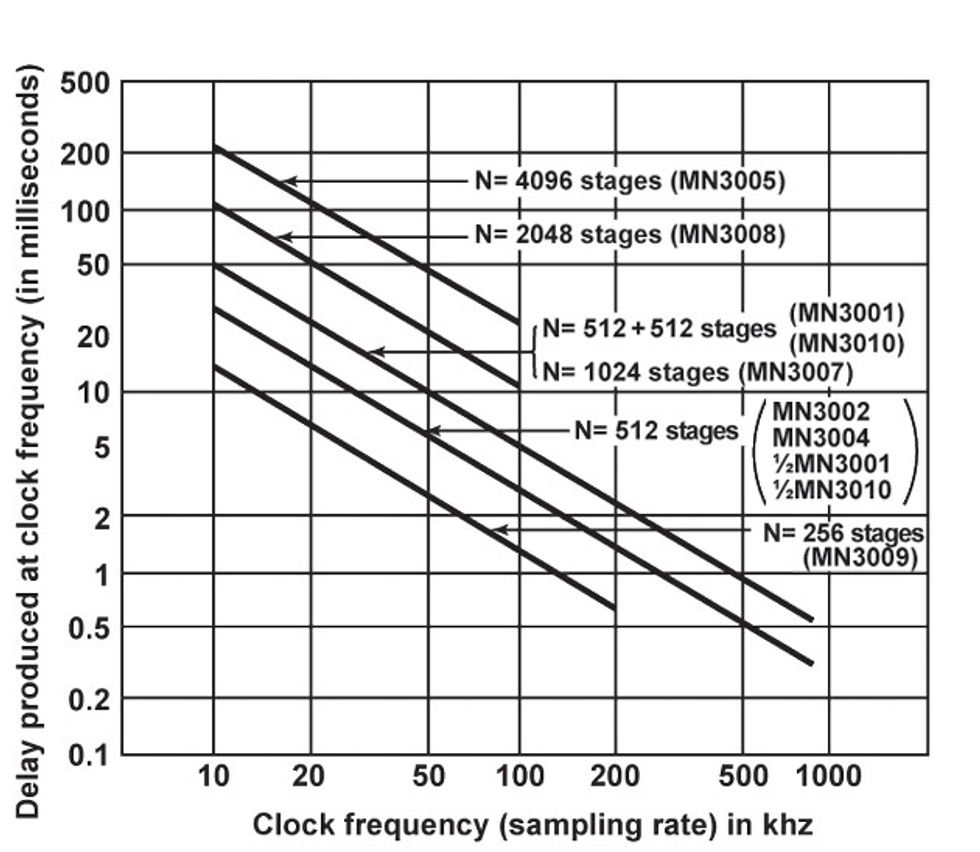
Table 1 — Delay times available from 512-, 1,024-, 2,048-, and 4,096-stage Panasonic BBD chips at various clock frequencies and sampling rates.
Table 1 shows how much delay time can be expected from the various Panasonic/Matsushita chips at different sampling frequencies. A pair of 4,096-stage chips in series can produce around 500 ms with respectable bandwidth. A number of commercial delays have gone this route, often with a switch to select between the outputs of the first or second BBD. (It should be noted that, though there are two chips in these designs, both chips are driven by a single clock.)
All the Trimmings
All BBD chips require what is referred to as a bias voltage. If the audio signal does not come riding into the chip sitting on top of a particular DC voltage, it won’t make it to the other side. As a consequence, nearly all pedals that use BBDs, regardless of effect type, will have a small bias trimpot (separate from the one used for balancing output signals). Some pedals with cascaded BBDs may have a single trimpot providing the same correct bias for all BBDs used, but the effectiveness of such a setup would be due more to a lucky guess than anything. Optimal audio quality occurs when every BBD in the circuit has its own trimpot for custom-tailoring its bias. It’s more work and increases production costs, but it makes for a better transfer between chips and is worth the additional labor, parts, and space.
The trimpot for adjusting a chip’s DC bias voltage is usually located somewhere near the delay chip’s input pin. If that bias voltage is too high or too low, you won’t hear any signal from the BBD. If it is just a little high or low, you’ll hear output, but it will be distorted. So if you have an old BBD device that doesn’t seem to be working (or sounding quite right), it’s worth opening it up and fiddling with this trimpot to see if that fixes things. There’s no risk of damaging the BBD or overall circuit if you simply let your ear guide you as you adjust it to restore audio quality. But when there’s more than one BBD in series and you can't hear the impact of each separate adjustment, it’s handy to have an oscilloscope so you can measure each chip’s output for minimum distortion as you adjust its bias trimmer.
Typical BBD-based effects have anywhere from one to four trimpots on the circuit board. As previously noted, some designs also have a trimpot for balancing output between two BBD outputs—and this is also found very close to the chip. Further, BBD effects in which feedback is used (like flangers and echoes), often have another trimpot for adjusting maximum feedback before howling or oscillation set in. This is usually found close to where the feedback is returned. Finally, there may also be a trimpot for adjusting the maximum delay time. This is useful for when, between like-valued BBD chips, there’s variation in where the clock-noise filtering begins to roll off top end and, consequently, the clock speed has gone low enough to be audible.
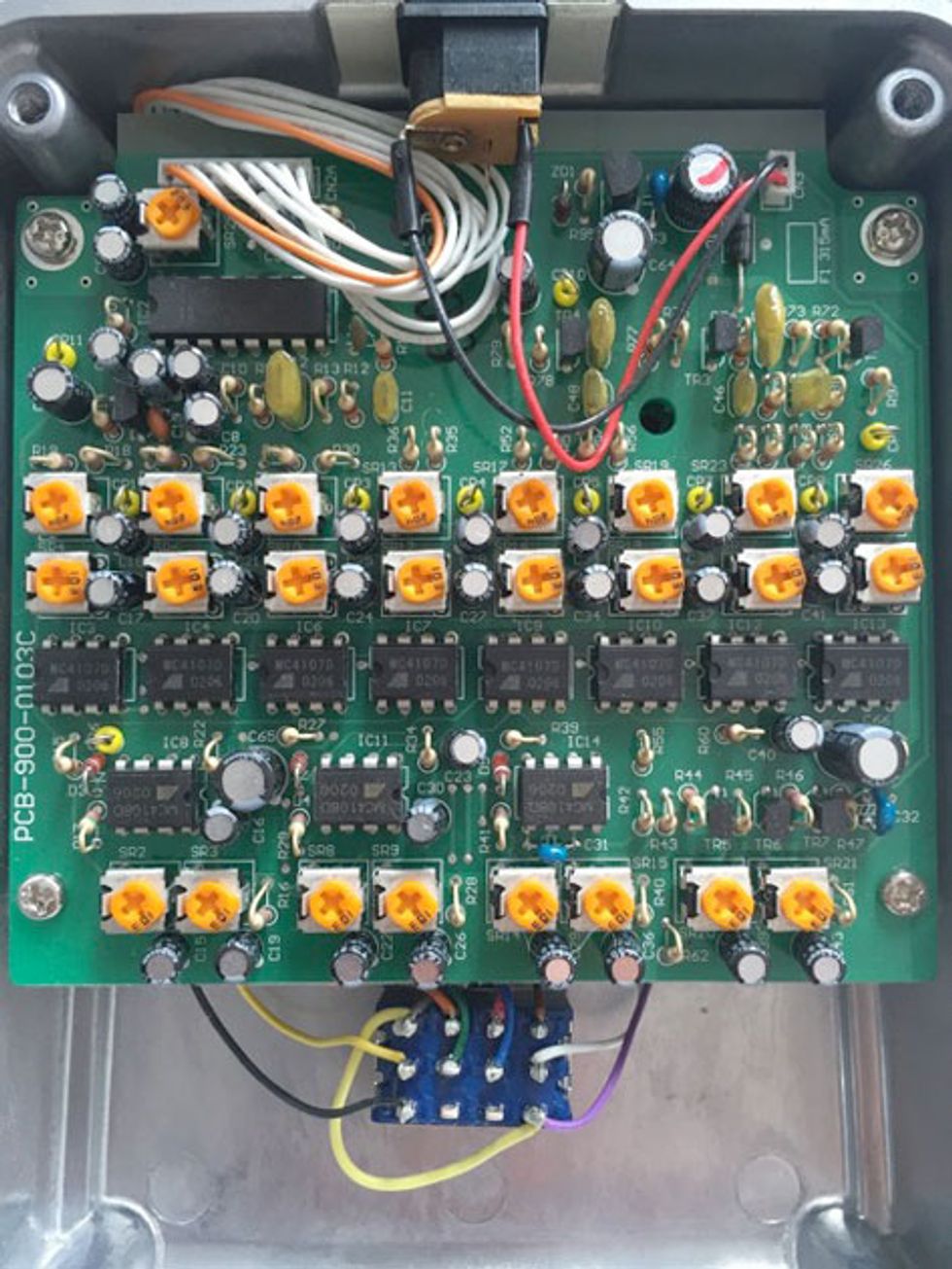
As you’ve probably gathered by now, when there’s more than one BBD chip in an effect housing, these trimpots can appear in duplicate or triplicate. For example, as noted earlier, the much-coveted Maxon AD-999 delay eschews high-capacity chips in favor of eight 1,024-stage chips, resulting in 25 total trimpots! Meanwhile, Electro-Harmonix’s most recent reissue of the Deluxe Memory Man has a bias trimmer for each of its two 4,096-stage BBDs, and an output balance on the second one, but it also includes a small gain stage for each BBD to compensate for potential signal loss (all BBDs lose a tiny bit of signal in comparison to the dry path), which means there’s a trimpot for each gain stage, too. Needless to say, when it comes to repairing or recalibrating a BBD-based effect, it pays to know where all the specific trimmers are and what they do! To aid in the process, track down a schematic and—if possible—a service manual for your pedal’s circuit.
Even simple effects with BBD chips typically have one to four internal trimpots for adjusting things like bias voltage, output balance, maximum delay time, and feedback. As you can see from the guts of this Maxon AD-999 analog delay, each BBD chip can exponentially increase the number of trimpots. Photo by Mark Hammer
Whoa, Slow Down!
As mentioned earlier (and as revealed in Table 1), shorter and longer delays can be produced by clocking a chip faster or slower. But there are limits. You can’t transfer the samples inside the chip too slowly (which is why Table 1 doesn’t go below 10 kHz), but you also can’t clock them too fast either—otherwise the sample-transfer process gets corrupted.
A BBD chip’s clock input pins have what is referred to as input capacitance. For our purposes, we’ll simply say that this capacitance can “dull” the clock pulse and turn it from square-ish to more triangular. When the clock frequency is low enough, the capacitance has no effect and the clock pulses are able to instantly switch the transistors in the chip that feed the samples to the next. But as the clock frequency increases, that input capacitance begins to add some lag and to turn what started out as a pretty square (i.e., either on or off) clock pulse into something more triangular. The near-instant switching action that normally yields seamless taking and passing of samples now begins to have a gap, as it takes longer for the transistors to be switched on. The gap itself is not directly audible since it is on the order of microseconds. But imagine a movie with a blank frame inserted between each successive image. It simply won’t look the same—the seamlessness of the flow of samples matters. Consequently, data sheets for many BBDs indicate a maximum clock frequency, beyond which performance will suffer. Table 1 shows that many common Matsushita chips can’t normally be clocked faster than 100 kHz.
Second-generation Matsushita chips had about 700 pF of capacitance for each 1,024 stages on the chip. For example, a 4,096-stage MN3005 or MN3205 would have an input capacitance of 2800 pF. In contrast, Reticon chips only had 110 pF for the same pins. Why does this matter? For long delay, it doesn’t. For flanging, where the most dramatic effects are produced by shortening the time delay to something almost negligible, you want a chip that is tolerant of very high clock frequencies (remember, faster clocking results in shorter delay time). The Matsushita chips weren't comfortable being clocked much faster than 100 kHz, while the Reticons were good up to 1.5 MHz. If you ever wondered why that A/DA Flanger or Boss BF-1 sounded so much better than your Boss BF-2, it’s because your Matsushita MN3207-based BF-2 couldn’t delay any shorter than 1 ms, while Reticon-based pedals could zip well below 1 ms with ease.
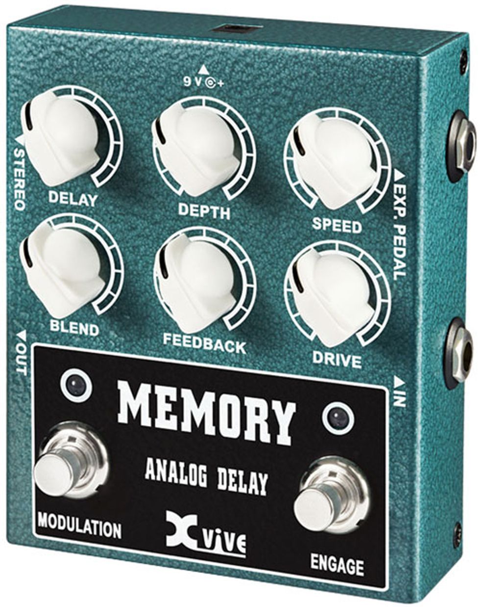
Xvive Audio manufactures replicas of the Matsushita MN3005 chip found in original Electro-Harmonix Deluxe Memory Man pedals—as well as in its own W3 Memory Analog Delay.
But don’t blame the Matsushita BBDs too much. They were limited by their companion clock generators: the MN3101 (for MN30xx chips) and MN3102 (for low-voltage chips). These provided an inexpensive, simple, compact solution for directly driving Matsushita’s BBDs, but they couldn’t adequately overcome that clock-pin capacitance. They were great for chorus or medium-delay echo, but you couldn’t get them to clock fast enough for great flanging, and they couldn’t handle the total capacitance of more than 8,192 stages (i.e., from a pair of 4,096-stage chips) needed for longer delay times. However, when properly buffered to overcome that capacitance, Matsushita BBDs can be pushed much higher—just like a buffered guitar signal can travel long cable distances and still retain treble. I’ve witnessed MN3207s pushed to 1.5 MHz clock rates without difficulty.
Can it work the opposite way? That is, can you buffer a clock chip to drive, say, four MN3005s (for a total of 16,384 stages, and 11,200 pF of clock capacitance)? It’s a bit like our earlier example of a 100-watt, EL84-powered amp: In theory, it could be done—but why not simply go digital?
Cut out That Racket!
BBD-based designs are susceptible to noise. The chips themselves differ in their individual noisiness, but the necessary inclusion of a clock only makes matters worse. There are two basic sources of noise to contend with in normal use. One is the sometimes-audible whine of the high-frequency clock that’s always running. If a 10 kHz clock pulse is required to achieve the desired delay time, there’s a chance you might hear that clock leaking through to other parts of the circuit, and eventually coming out your speakers.
Now let’s talk about the second kind of noise. We may think of BBDs as providing a seamless, continuous representation of the input signal, but in actuality there are teensy-weensy steps between each successive sample, and those can create the illusion of high-frequency content riding on top of the actual signal. This is referred to as aliasing noise.
Historically, these two noise sources have been addressed using some combination of the following five strategies:
- Low-pass filtering. A low-pass filter is placed before and after the BBD in an effort to eliminate everything above the highest frequency that’s intended to be audible. This approach is used in virtually all BBD-based effect devices.
- Gating. A noise gate is applied at the BBD output, so that any remaining BBD noise is killed when you stop playing. This approach is used in the Boss CE-1 Chorus Ensemble and A/DA Flanger.
- Treble manipulation. Treble is emphasized at the input and then de-emphasized in complementary fashion at the output. This restores normal tone to the dry signal, but cuts any hiss or clock whine added by the BBD to the delayed signal. This approach is used in the Boss CE-2 Chorus and BF-2 Flanger.
- Companding. Companding—compressing and expanding—keeps the audio input to the BBD at an optimal level, well above the noise floor, and restores dynamics after the delay is created. This approach is used in the Electro-Harmonix Deluxe Memory Man and Boss DM-2
- Output balancing. As noted earlier, a trimpot is used to balance BBD levels in an effort to cancel out clock noise.
Ironically, a great deal of the “warmth” that players are referring to when discussing analog delays is actually a result of the low-pass-filtering strategy for eliminating clock noise. The thing is, if you use the same sort of filtering in a digital delay circuit, it can sound remarkably similar to analog!
Grading BBD Chips
For the longest time, there were effectively three manufacturers of BBDs: Reticon, Panasonic/Matsushita, and Philips. I’m not sure about Philips, but Reticon stopped making BBDs in the early ’80s, so anyone trying to repair or clone a Reticon-based pedal has to pay astronomical prices for NOS replacements. Panasonic (formerly Matsushita) stopped production in the late ’90s, but since there was demand for them, several companies resurrected clones of the old Matsushita chips. In the late 1990s, Belling began reissuing copies of Matsushita’s MN3208 and MN3207 with the designation BL3208 and BL3207, and more recently Coolaudio started producing clones of the MN3207, MN3208, and MN3205. Even more recently, China-based Xvive Audio (which, not so coincidentally, has its own line of very affordable stompboxes) began making replicas of Matsushita’s venerable MN3005. The chip is available for sale separately, but is also used in the company’s higher-end W3 Memory pedal—which was designed by Howard Davis, manager of analog circuit design at Electro-Harmonix from 1976–1981. The chip itself isn’t cheap, but it’s not prohibitively priced, either. Sadly, new Reticon chip clones don’t seem to be on the horizon.
As with seemingly everything else in guitar gear, there are many legends attached to different BBD chips. One is that there’s a difference between generations of Matsushita chips—particularly between the MN30xx series and the lower-voltage MN32xx series. Certainly the earliest Matsushita chips (like the MN3001 and MN3002 used in the Boss CE-1, and the MN3010 used in the A/DA Flanger) were quieter and could be clocked faster (because they had a lower clock-pin capacitance). But the quality of the signal in any of the various issues is still very much a matter for debate. I’m not so sure specs and data sheets capture the differences people think they hear.
With regard to the difference between the MN30xx and 32xx generations, recall that BBDs can’t pass an audio signal unless it’s sitting atop a DC bias voltage (derived from the power supply). In the 1980s, the power supply for the bias voltage would’ve usually been a battery. As the battery aged and the voltage dropped, dividing down that voltage could result in the “wrong” bias voltage, and sound quality would suffer. It seems a silly consideration now, in an era of plentiful power supplies, but back then there were no pedalboard power bricks, and you couldn’t expect musicians to keep changing the battery or opening up a pedal to twiddle the bias trimmer. So Matsushita designed the MN32xx series to operate off of 5 volts, and the bias would be derived from that 5 volts. The pedal’s 9-volt battery would then be down-regulated to provide a stable 5 volts for the BBD and its bias until the battery dropped below around 7 volts—at which point it wouldn’t have enough juice to power the pedal anyway. The redesign allowed the MN32xx series to work flawlessly without any drift in the bias as the battery aged. But with contemporary powered pedalboards, concerns about supply-voltage drift are history.
Tying It All Together
Happily, in comparison to modern production of vacuum tubes, the quality of BBDs currently in production is generally no different from those made in bygone days. A new MN3205 is the equal of a NOS version from 1981. Further, many of today’s effect designers have mined the rich vein of tricks and strategies for extracting the best out of this technology. That said, there were a lot more BBD types and configurations available 30 years ago, and I do wish someone would reissue certain models—like the Reticon SAD-1024 used in great old flangers from Boss, A/DA, EHX, and MXR (as well as in the ADR S24 Scamp), and the multitap Matsushita MN3011, which powered the legendary A/DA STD-1 Stereo Tapped Delay exploited to such great effect by Allan Holdsworth. But that hasn’t stopped current designers from coming up with feature-rich pedals yielding remarkable sounds and options that nobody dreamed of in 1979—including things like tap tempo and digital control.
Although many stompbox companies are migrating to the digital domain, I find it both interesting and heartening that new BBD pedals are unveiled quite often these days. Which prompts the question, is there anything about using BBDs that’s somehow inherently better than state-of-the-art digital circuitry? Probably not. And certainly, back in the day when all effects were analog, there were both stellar and ho-hum products. But the reason many BBDs have been reissued in recent years is not simply due to romanticized notions about the good ol’ days. When all is said and done, it’s because both the established old-school BBD know-how and newly discovered circuit-engineering tricks—and yes, even the things that have to be done to keep noise down—simply sound great when done well.
Special thanks to Joel Korte at Chase Bliss Audio, Steve Daniels at Small Bear Electronics, and Mike Irwin.


