
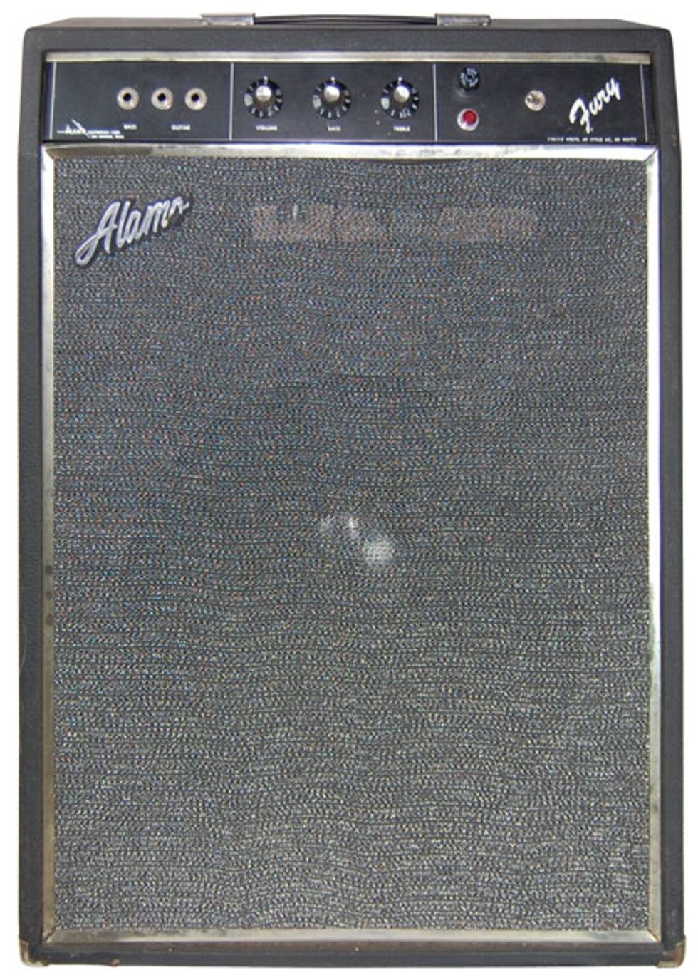
Alamo Fury Combo
Once again I’m going to stray from the typical format for this month’s column. Instead of attempting to answer a reader’s question, I’m going to feature an amp that came in for servicing. Okay, if you really need a question, we’ll go with, “Hey Jeff, I just acquired this cool old amp. I don’t know too much about it, but it’s dead. I’d like to know if it’s repairable, but I don’t know what it’s worth or how it sounds, so I don’t want to invest too much in the repair.”
The amp in question is an Alamo Fury combo. Remember the Alamo? No? Me neither. I don’t know if I’ve ever seen one before, and if I have, it wasn’t this model. This combo has two 7868 output tubes and appears to have a single 15" speaker. But wait—there’s only one 12AX7 tube. Hmmm, a couple of possible scenarios here, so let’s see what’s going on under the hood.
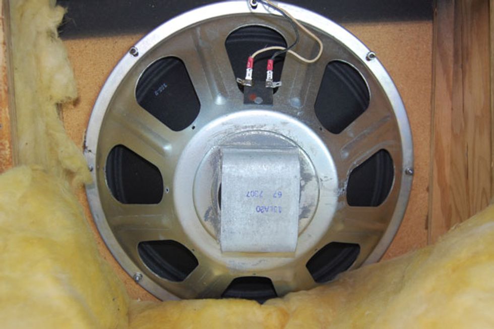
Photo 1
Because the output is directly wired to the speaker, the first move is to remove the rear panel of the speaker enclosure and disconnect the speaker. This reveals a stock 15" speaker (Photo 1) stamped 67-7307. This would be an Eminence speaker (67) that was manufactured in the seventh week of 1973 (7307).
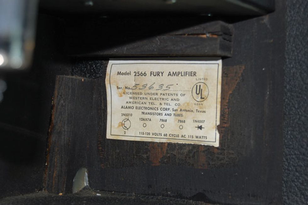
Photo 2
So now it’s on to the electronics. Upon pulling the chassis, the question of a circuit with only one 12AX7 is put to rest. That tube was used as a phase inverter, which means that the front end of the amp is solid state. I would have already known this had I taken the time to look at the tube chart first (Photo 2), which is on the inside wall of the cabinet. It’s actually a “hybrid” chart and happily touts the fact that the Fury’s preamp is powered by a 2N5210 transistor! It also appears to tell us that the amp has a solid-state rectifier, as denoted by the diode symbol. Okay, mystery solved. Now let’s see why the amp will not power up.
Multimeter in hand, I did a quick check of the fuse. It shows continuity, although I don’t think a 10-amp fuse belongs here. That could easily cause transformer failure, but let’s continue. After installing a more appropriate fuse, I began measuring voltages starting with the AC line voltage, which we find stops right after the fuse holder. By process of elimination, if the fuse isn’t bad, the fuse holder is. Replacement of the fuse holder yields … an illuminated pilot light. Progress!
A quick signal at the input and load on the output shows that the amp is working, but barely. More issues. A sound check with a guitar and speaker reveals that the amp has weak output with hum. Okay, this sounds like a filter capacitor issue. Seeing as how this amp has a chassis mounted multi-cap can, I opted to reduce the time and expense by installing discrete filter caps.
One important thing to bear in mind when doing a repair this way is to keep all the capacitor ground connections as close to the original ground point as possible, as this is the way the amp was designed. It may be easier to install the capacitors in other locations, but this often results in increased hum. Now, let’s see what the amp does.
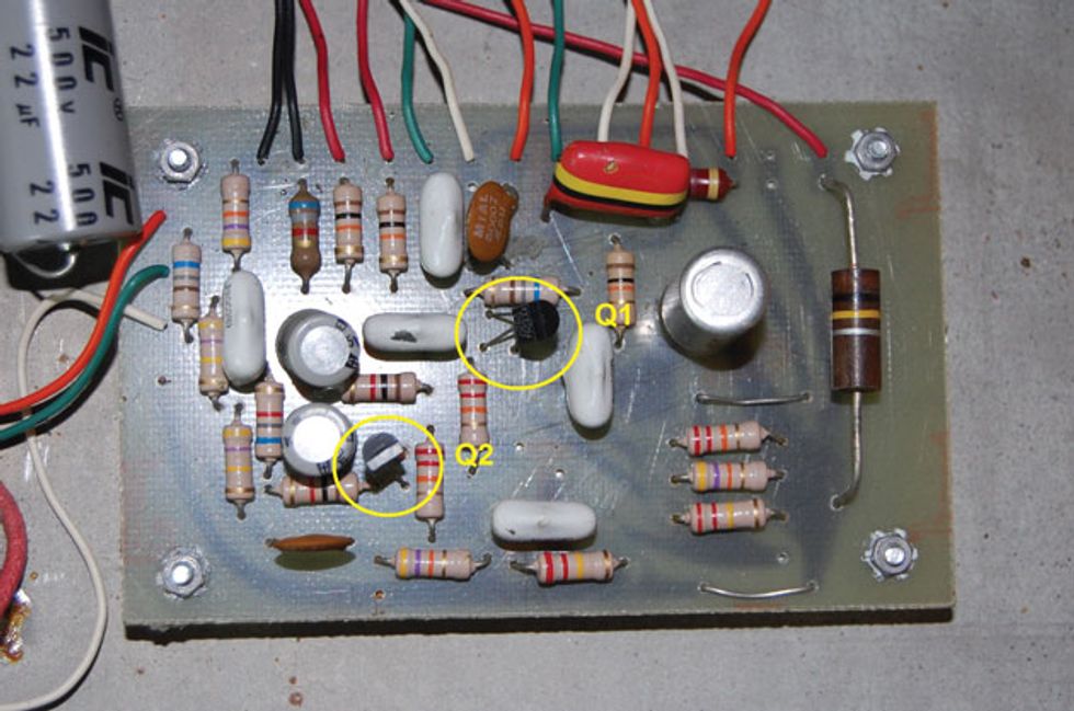
Photo 3
Power on, plug in, turn up and … we’re good. The amp seems stable and, while it’s not going to set the world on fire, seems to function as intended. Could the amp benefit from a new set of tubes? Probably. And maybe a new, more efficient speaker? Probably. But I’ll leave that to the customer, should he wish to invest further in his acquisition. But hey, while I have the amp on the bench, let’s learn a bit about it and see if it could benefit from any improvements.
The preamp board is designed around not one measly transistor, but two (Photo 3). The first is used as the initial gain stage for the inputs and drives the tone controls. The second re-amplifies the signal from the tone stack and drives the phase inverter tube. Surely there must be some way to enhance the performance of these devices—and there is. Both transistors use a 1k emitter resistor (Photo 4).
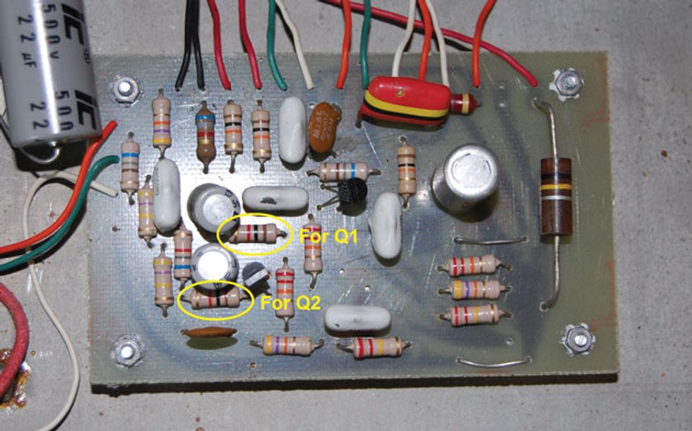
Photo 4
Placing a capacitor across these resistors is the same as placing a bypass capacitor across a cathode resistor in a tube amp. Too large a value here might be too much of a full range boost for this little amp to handle, but because this was designed as a bass amp, a bit more highs may add some needed sparkle for guitar. I found that a value of 0.1 µF added a noticeable increase in high end.
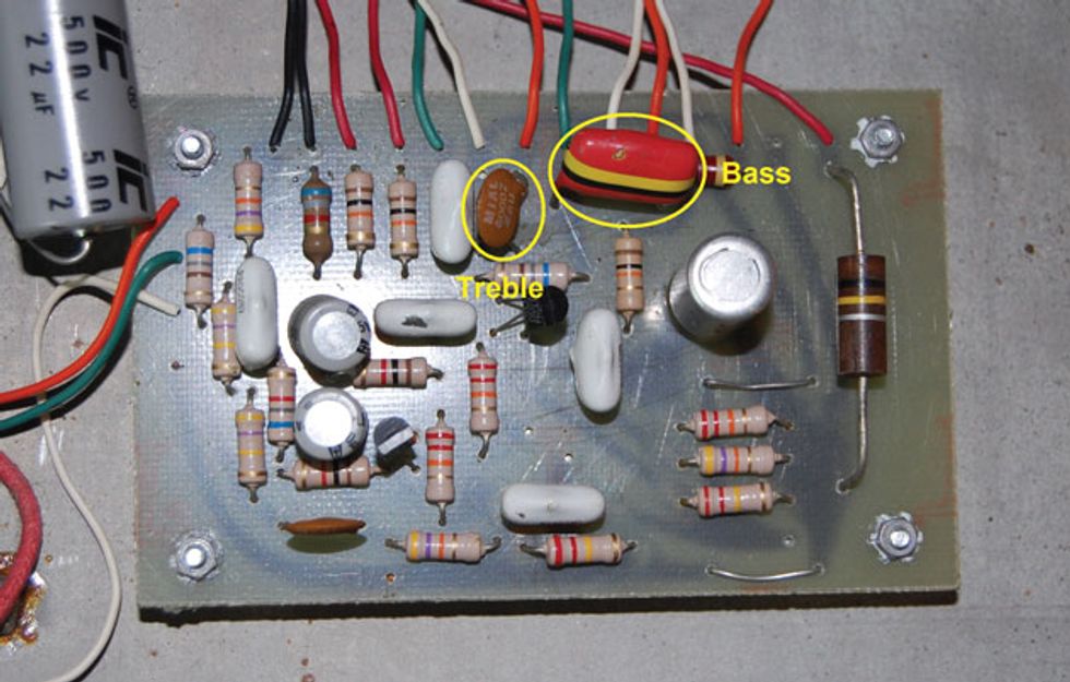
Photo 5
Placing it across the Q1 resistor gives the increase before the tone stack, which means it’s controllable, while placing it across the Q2 resistor gives the boost just prior to the phase inverter. It’s a matter of sonic preference. Also, Photo 5 shows the tone stack bass and treble caps, which can further alter the amp’s tone.
There you go. Now maybe this amp will be an Alamo to remember!
WARNING:
All tube amplifiers contain lethal voltages. The most dangerous voltages are stored in electrolytic capacitors, even after the amp has been unplugged from the wall. Before you touch anything inside the amp chassis, it’s imperative that these capacitors are discharged. If you are unsure of this procedure, consult your local amp tech.


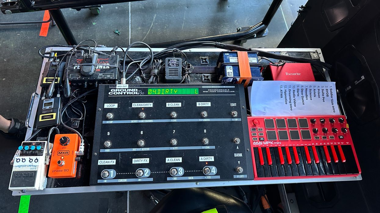


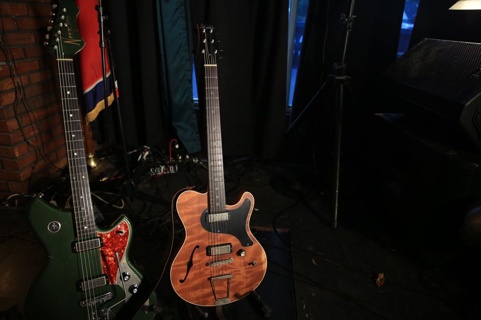
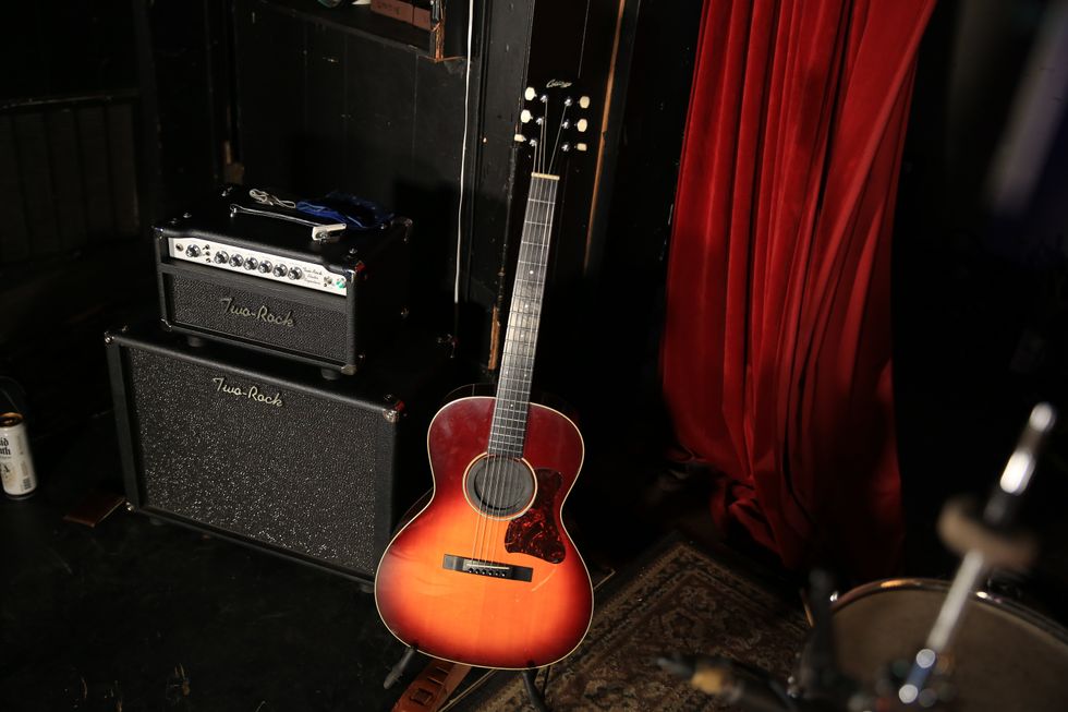
 Miller’s Collings runs into a Grace Design ALiX preamp, which helps him fine-tune his EQ and level out pickups with varying output when he switches instruments. For reverb, sometimes he’ll tap the