Greetings, amp fanatics, and
thank you for reading my
column and submitting your
questions and comments. While
I typically pick one of your
questions to discuss here, this
month I’m breaking with tradition.
I recently had an unusual
combo come across my bench,
and I felt it would make a great
topic for a column. The amp—a
Sound X-305-R—belongs to
a friend of mine named John
Ingram, and it’s a model I had
not previously seen.
Since the amp was already in good working order, though a bit lackluster in the performance category, John brought it in for some basic service and also asked me to “turn it into something cool.” That sounded like a good idea, so that’s exactly what I did. In case you ever come across your own Sound amp, I’ll explain these simple but effective modifications. But first, let’s investigate the history of Sound amps.
While doing research for this column, I read a comment regarding Sound amps posted by Andy Fuchs of Fuchs Audio Technology. So I contacted Andy and asked him what he knew about these rare birds.
“I know that they were made on Long Island—Mineola to be exact—by John Daugherty,” Fuchs told me. “Daugherty may have worked for Ampeg and/or Oliver [Amps]. I don’t know how long Sound was in business, but I know Daugherty ended up working at Marlboro Sound Works—along with Ed Finger, a former Ampeg sales person—selling solid-state amps of various sizes and shapes. Musical Instrument Corporation of America owned Marlboro, which eventually folded. I’ve seen and heard some Sound amps that actually sounded pretty good. Every one I ever saw was covered with gray vinyl and had aluminum accents on the box. I don’t know much else about them.”
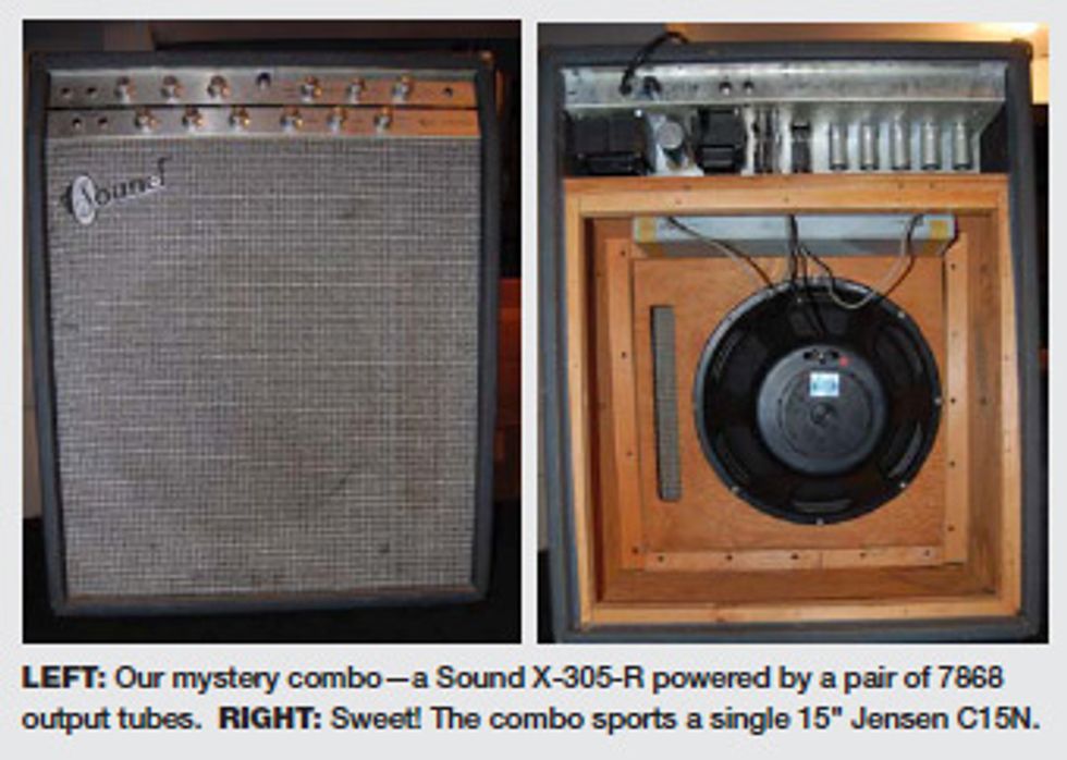
Well, as you can see in the photo, this amp is indeed covered in gray vinyl with a brushed-aluminum faceplate, aluminum knobs, and even narrow aluminum rests on each side of the cabinet in lieu of feet. The combo sports a single Jensen C15N with a manufacturing code of 220629. The reverb-tank date code of 6649 and the mid- to late-’66 date codes on the pots suggest the amp was manufactured in late 1966.
The X-305-R has two channels, each with two inputs and Volume, Treble, and Bass controls. There is also a Reverberation control to select reverb for Channel 1, Channel 2, or both, along with Depth and Rate controls for the tremolo. The tremolo is a bias-modulated circuit, which means it affects the output stage. Because the amp only has one output section, the tremolo works for both channels. Other front-panel controls include rotary switches for Power and Polarity (ground).
The amp’s tube complement consists of four 12AX7s, one 12AU7, and two 7868 output tubes, the latter of which appeared in some ’60s Ampegs. Inside, the similarity to ’60s Ampegs was so strong that I wondered if Ampeg produced Sound amps as an in-house brand, perhaps for a chain of music stores. I couldn’t confirm this, so let’s stick with the “former Ampeg employee” story.
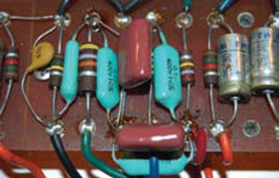
Testing the amp, I found it a bit on the weak side, with no appreciable gain or overdrive, and both channels sounded identical. The tremolo was decent, but even at the slowest setting it was a bit fast. Here, you see the capacitors that form the tone stack for Channels 1 and 2.
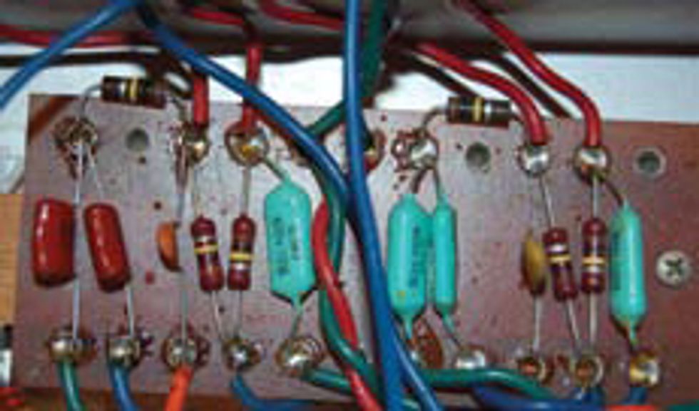
The two blue caps, 100k resistor, and tan ceramic cap to the right of the blue wire are the components for Channel 1’s tone stack. These consist of a 0.1 μF, a 0.039 μF, and a 330 pF capacitor— an atypical set of values that definitely gives the amp its own sonic character. The components to the left of the blue wire are for Channel 2’s tone stack, which I decided to replace with more traditional “British” values. I changed both capacitors to 0.022 μF and the ceramic cap to 470 pF, which yielded two different-sounding channels. Using an A/B footswitch, John could have channel switching on the cheap!
This next photo shows a 1.5k resistor attached to a cathode of V4. This resistor was originally not bypassed (that is, it had no capacitor in parallel with it), so I bypassed it with the 2.2 μF 25V capacitor shown here. This greatly increased the gain in that part of the circuit, which allowed the amp to develop substantially more overdrive.
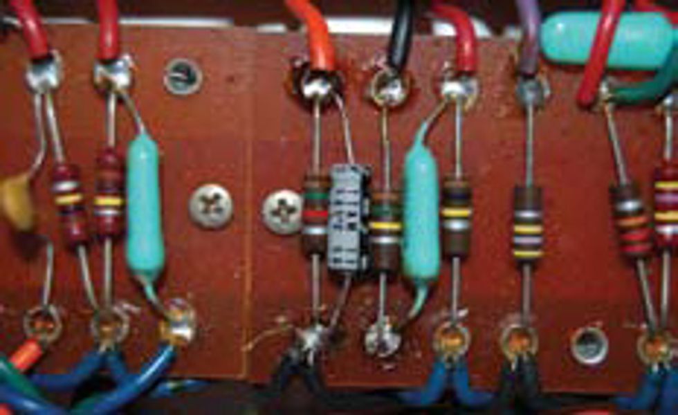
This last photo shows a pair of brown 0.047 μF capacitors paralleled across an existing pair of blue 0.047 μF caps. This is the tremolo’s oscillator circuit. As previously mentioned, even with the Speed control fully counterclockwise, the speed was originally far too fast to be practical. Increasing the capacitance by paralleling these caps slowed the oscillator enough to provide a nice, swampy feel.
Because this is a bias-modulated tremolo, the louder and harder you play, the less the effect is apparent. But you can definitely use this to your advantage. For instance, you can play deeply tremolo’d chords and then crush into a solo with almost no trace of tremolo, only to have the tremolo fade back in as the notes decay or as you reduce your Volume control. Very cool.
So there you have it. More sounds from the Sound!
 Jeff Bober is one of
the godfathers of the
low-wattage amp revolution,
co-founded and was
the principal designer for
Budda Amplification. Jeff recently launched EAST
Amplification, and he can be reached at
pgampman@gmail.com.
Jeff Bober is one of
the godfathers of the
low-wattage amp revolution,
co-founded and was
the principal designer for
Budda Amplification. Jeff recently launched EAST
Amplification, and he can be reached at
pgampman@gmail.com.


![Rig Rundown: Russian Circles’ Mike Sullivan [2025]](https://www.premierguitar.com/media-library/youtube.jpg?id=62303631&width=1245&height=700&quality=70&coordinates=0%2C0%2C0%2C0)