


Hello again Ask Amp Man fans, and thanks for coming back to the column month after month. This month yet another cool amp crossed my bench that I thought would be a good subject for my offering here in the pages of Premier Guitar.
The original Thunderbolt has its control panel at the amp’s bottom rear. The control panel is top mounted
in today’s reissue version.
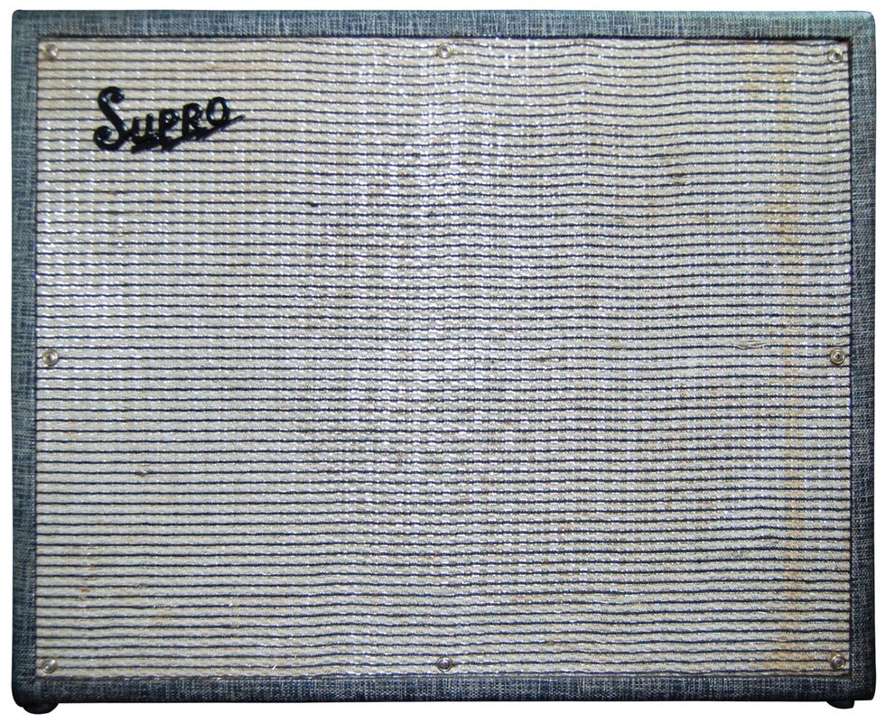
Most of us have heard stories about how the iconic tones of our favorite players were recorded—and this particular amp is often part of that lore. Although there have been yarns both confirming and denying the use of this model on a certain English band’s first album, I’m not even sure if the band’s Tele wielding (at the time) guitarist with the initials J.P. can remember with absolute assuredness. That said, we’re going to assume the Supro S6420 Thunderbolt was the magic box that gave us the crushing guitar tones on Led Zeppelin and have a look inside one.
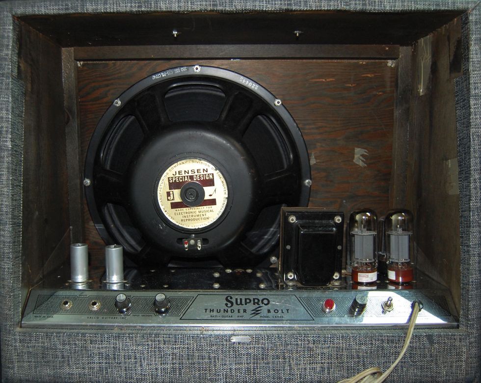
The first thing we notice, both from the control panel as well as a quick look under the hood, is that this is a pretty basic amp: two jacks, two knobs, and an on/off switch. What more do you need? Well, today, maybe a crap-load of pedals to get a monstrous tone at bedroom levels. But not the iconic players of yore! A great player, a good amp, a good mic, and a great engineer was all it really took in the ’60s. Obviously this amp is capable of some great tone and drive, but can it be made “better?” Let’s try a couple of simple mods to see if we can improve on this classic.
Let’s try mod one. First, this is a cathode-biased amp, meaning the output tubes develop their bias across a cathode resistor as opposed to having a fixed bias voltage supplied to them. I actually like this type of output stage and use it in all my EAST amps. The unusual thing is the cathode cap is un-bypassed, meaning there is no capacitor in parallel with it. Almost all cathode-biased amps have bypass caps, so let’s see if adding one will be an improvement.
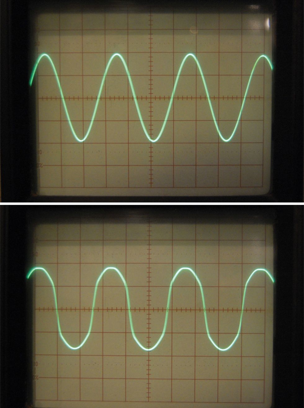
Photo 1 (top) and Photo 2 (bottom)
Photo 1 shows the input signal to the amplifier and Photo 2 shows the output at the start of clipping. This is not really a true representation of the input, but this is typical of a non-bypassed cathode-biased amp.
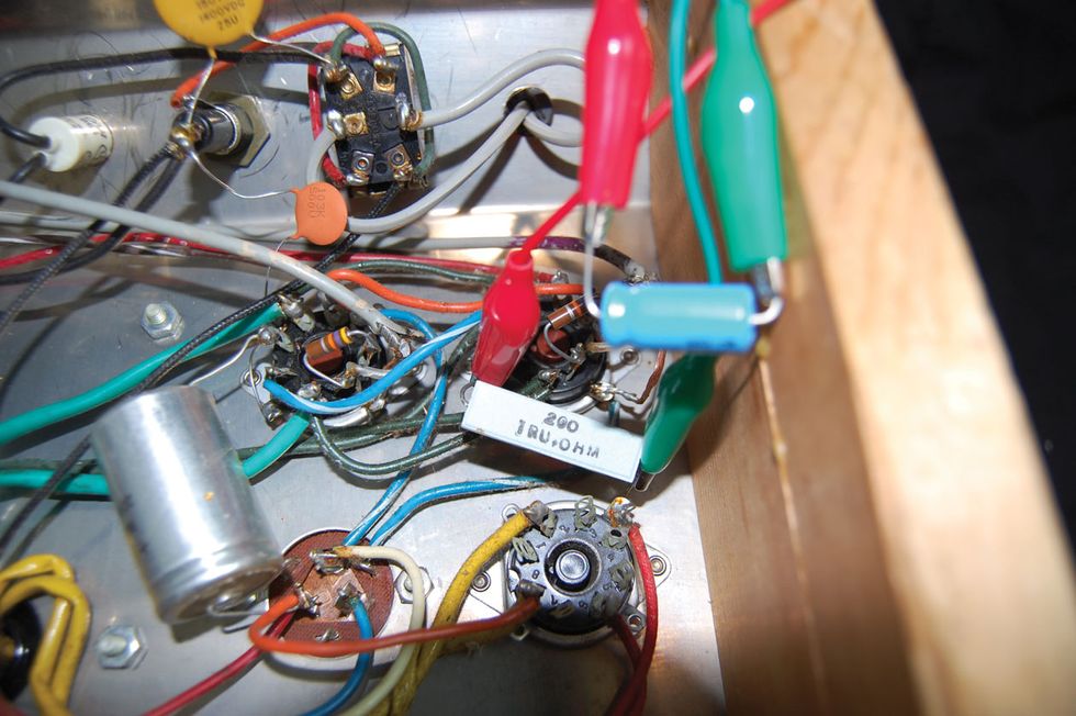
Photo 3
Let’s use a pair of alligator leads and temporarily attach a bypass capacitor (Photo 3) and see what happens. In Photo 4, you see the result: a much more perfect sine wave. Okay, a quick soundcheck reveals … a bit of disappointment. The amp has lost some of its character. It’s just not as “snotty” when you really lean into it with a Tele.
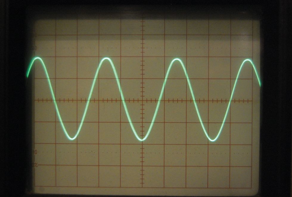
Photo 4
That said, remember, this amp was marketed as a guitar/bass amp and does have a 15” speaker. This might be a good mod for bass, but it certainly lost a bit of guitar magic. No bypass cap for you, Thunderbolt!
And now, mod two. This amp suffers the same design tragedy as some of the early Fender Bassman amps: an unused gain stage! A sacrilege, indeed! Okay, not always, but it can also be useful for modding. After a look at the input wiring, let’s give it a try. Carefully examining the circuitry for the two input jacks, I realize both inputs are identical. Well, what good is that? Let’s turn one into a higher-gain input for some versatility.
WARNING:
All tube amplifiers contain lethal voltages. The most dangerous voltages are stored in electrolytic capacitors, even after the amp has been unplugged from the wall. Before you touch anything inside the amp chassis, it’s imperative that these capacitors are discharged. If you are unsure of this procedure, consult your local amp tech.Photo 5 shows the five components necessary to do this quick mod—which is completely reversible, by the way. Here are the steps for attaching the components to the unused side of the first 12AX7 preamp tube. And remember, the pin count starts at the space on the socket and moves clockwise, starting at pin 1. First, there is an orange wire coming from the first input jack. Let’s disconnect it from the terminal board. Next we’ll connect one side of a 10k resistor to pin 8 of the tube socket. Connect the other side to the first (far left) terminal of that same terminal strip. This terminal is attached to the chassis and will serve as a ground point.
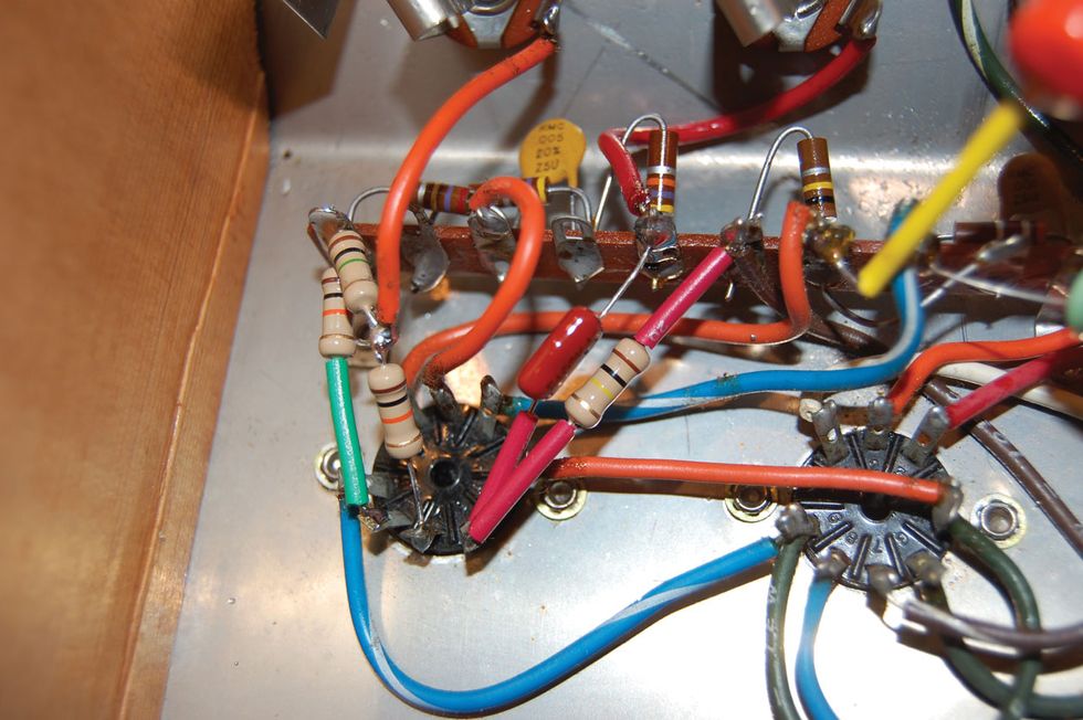
Photo 5
Now let’s connect both a 100k resistor and a .001 µf capacitor (anything over a 400V cap is fine here) to pin 6 of the socket. Connect the other end of the capacitor to terminal 5 on the terminal strip, which has the red wire coming from the second input jack. Connect the other end of the 100k resistor to terminal 6. This has the brown wire and another one or two 100k resistors attached to it. (Note: This is the high-voltage supply, so always be sure all the filter caps have been discharged prior to working around high voltages!) Last, let’s take a 1M and a 10k resistor and solder one lead of one to one lead of the other, placing the two resistors in series. And let’s try to keep them very close to each other. Twisting them together before soldering works pretty well.
Next, we connect the 10k end of the pair to pin 7 of the tube socket. And connect the 1M end to terminal 1 of the terminal strip (ground). We take the orange wire coming from the first input jack and solder it to the junction of these two resistors. That’s it. You’re done. (If you didn’t follow that, go back and read it again.)
Now we’ve effectively cascaded the two gain stages when input 1 is used. Plug into input 2 and you’re back to the stock configuration. Input 1 is now brighter than 2, but in order to keep this mod really simple and reversible, we needed to keep it that way. That said, the tone control in this amp does a lot, so dial it back just a bit and the tone is right back in the ballpark of the stock input.
When I told my editor I was doing a column on the Thunderbolt, he asked if I could do a quick comparison to the new reissue. While I’ve not had the opportunity to audition the reissue, I took a quick look at the amp and its feature set. The first obvious thing is the control panel is now top mounted, which actually makes the amp easier to use, but what’s more interesting is a look at the two inputs on the control panel. They’re labeled “lo” and “hi.” Their specs even refer to the high as “hot.” Might the new Thunderbolt have taken advantage of that second gain stage? Also, on the new 6420+ model, there is a 3-position rectifier switch. I assume it switches between tube and solid-state rectification for the lower and higher power, but I’m guessing that center position might just be adding the cathode bypass resistor we spoke of earlier. Well, whatddayaknow!


![Rig Rundown: Russian Circles’ Mike Sullivan [2025]](https://www.premierguitar.com/media-library/youtube.jpg?id=62303631&width=1245&height=700&quality=70&coordinates=0%2C0%2C0%2C0)