Hi Jeff,
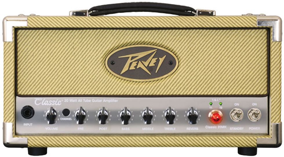
Is there any way to increase the clean headroom in a Peavey Classic 20 amp?
Thanks,
Jeff
Hi Jeff,
Great question—it has to be the most succinct one I’ve ever received. Of course, having a bit more information as to how you set the amp and what kind of guitar(s) you prefer might make it a bit easier to suggest modifications best suited for you, but I’ll give you a few different options and you can select those that seem most appropriate.
A bit of advice: Prior to late 2012 (when the company started rolling out revisions to this long-running amp line), Peavey’s Classic series used a construction technique where the three circuit boards in the chassis were all connected by quite a few individual buss wires and then folded over themselves into a “C” shape. The group was then positioned in place inside the folded chassis and mounted to the chassis via the pots and screws. This was actually a decent cost-cutting technique from a manufacturing perspective, but it made servicing the amp rather difficult. Thankfully, post-2012 Classic series Peaveys have reportedly been redesigned to rectify this difficulty.
If the boards from earlier Classics (like the one here) are removed and reinstalled more than a couple of times, the buss wire leads start to break, and at that point you’ll find yourself replacing all the buss wire jumpers. So pick the mod(s) you want carefully and try to minimize board removal and replacement.
The first modification I’ll suggest deals with the output stage. I recommend you do this one, as it works to keep the output stage a bit cleaner and more defined. It requires isolating the cathodes of the output tubes from each other. Some manufacturers have models that are designed and built like this, I’m guessing for this very reason. This amp is a cathode-biased amp and both output tubes share a common cathode resistor and capacitor. The mod requires cutting a trace, so it’s not for the faint of heart.
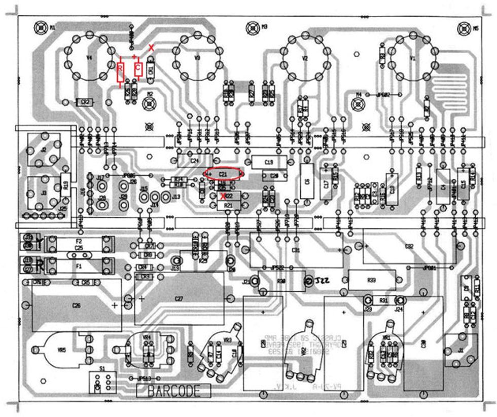
Fig. 1
Take a look at Fig. 1. You’ll see an “X” over a trace between V3 and V4. The trace needs to be cut in this area. Next, carefully scrape away some of the solder mask on the two necessary traces and install the “R” and “C” components. The “R” should be a 220-ohm resistor, at least 1W. The “C” can be anywhere between 4.7 µF and 10 µF, and at least 25V. The smaller value will reduce the low end just a bit, which is not necessarily a bad thing when looking for headroom in a low-power amp. Be sure to observe the polarity indicated by the “+” sign on the drawing.
Next, remove R22, indicated with an “X,” and change C21 (circled) to whatever value you chose for the “C” next to V4. Be sure to observe the polarity here, too. You have now isolated the output tube cathodes.
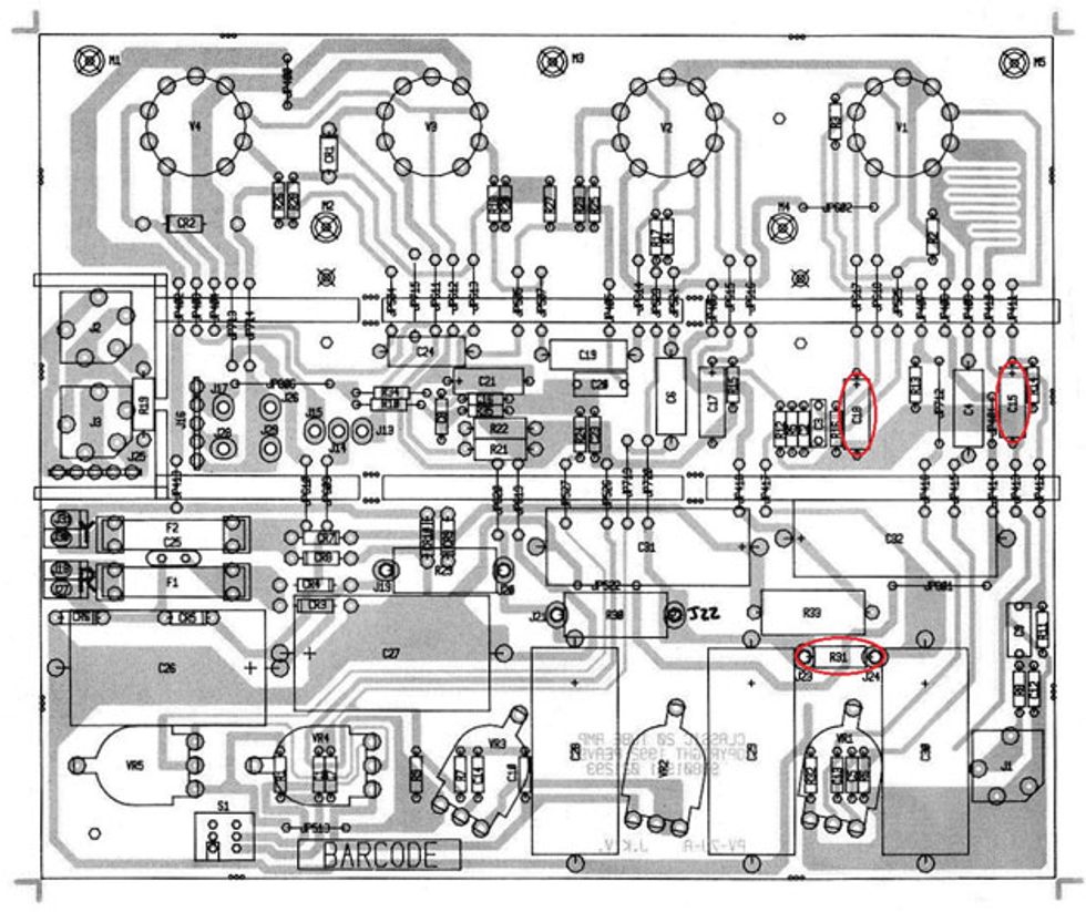
Fig. 2
Next, in the lower right corner of Fig. 2 you will find R31 circled. Remove this 10k value and replace it with a 4.7k 1W resistor. This will slightly increase the plate voltage on the first preamp tube and give you a bit more headroom there. You will also see C15 and C18 circled. For more headroom using humbuckers, I’d suggest removing C15 altogether or replacing it with a substantially smaller value such as a 0.47 µF or 0.68 µF. This will reduce the gain of the tube in the lower frequency ranges. The other option would be to swap C15 and C18. This will accomplish the same result in the first gain stage, but give the second stage a fuller frequency response.
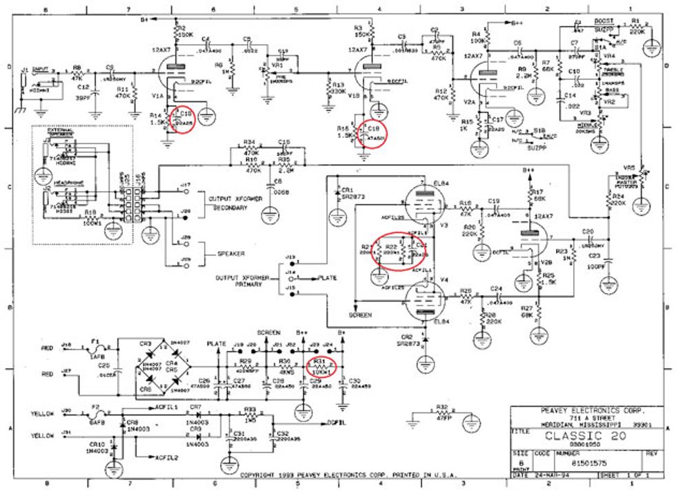
Fig. 3
Well, there you have it. Fig. 3’s schematic shows you the locations in which we made the changes. Hopefully this will give you a well-behaved and classy Classic.


![Rig Rundown: Russian Circles’ Mike Sullivan [2025]](https://www.premierguitar.com/media-library/youtube.jpg?id=62303631&width=1245&height=700&quality=70&coordinates=0%2C0%2C0%2C0)