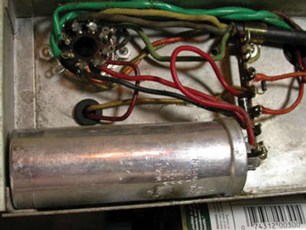
This vintage GA-79RTV has a non-original can cap.
Hi Jeff,
I’m doing a cap job on a Gibson
GA-79RTV. I can’t see the symbols next
to the respective connections on the
bottom of the cap can to verify which
capacitance values and voltages I need to
use as a replacement. The values listed
on the can are 80/450, 40/450, 30/450,
and 40/150. The amp schematic shows
two 20 μF, so I believe all I need are two
20 μF/200-250V electrolytics. Is that
correct? I’ve heard you should replace
old caps with a higher-voltage cap if
you can. Any recommended brands?
I recently replaced the caps and installed a 3-prong AC cable in a ’63 Gibson Skylark combo. Not a huge job, but it came out well and the amp sounds much better. However, this GA-79 is another animal! I’m planning on replacing all of the electrolytics, including the 30 μF/450V yellow Sprague. Would any electrolytic of that value be a proper replacement, or should I opt for a more expensive metal-foil type?
Finally, the fiber washers between
the tube socket screws and washers
have disintegrated after 40-some years.
The sockets are getting really loose
and I’m afraid the connections will be
jeopardized. Could I use small rubber
washers as a replacement? If so, any
suggestions for finding such items?
Thanks in advance.
—Mike Butler
Hi Mike,
Thanks for your question. For those who
don’t know, the Gibson GA-79RVT is pretty
cool—a true stereo amp with two discrete
output stages, each feeding a 10" speaker.
Each output stage uses one half of a shared
12AU7 as the phase inverter, driving a pair of
6BQ5/EL84 output tubes. This would generate
approximately 15 watts per side, making
this a 30-watt combo. The GA-79RVT also
included reverb and tremolo.
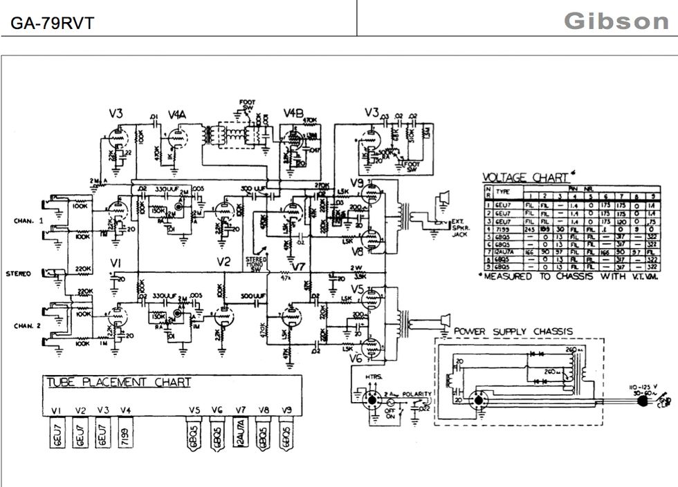
A mono/stereo switch allows you to use the amp in several configurations. Plugged into channel 1 with the switch in the mono position, the signal goes to both output stages and sound emanates from both speakers. However, because the reverb and tremolo are exclusive to channel 1, these effects are only present in the channel 1 speaker.
With the switch in the stereo position, the amp accepts dual signals from stereo guitars, such as Gibson’s ES-345 and ES-355. In this mode, the neck and bridge pickups feed separate channels. Because only channel 1 has effects, only one pickup can have effects.
Alternatively, you can plug a separate instrument into each channel, which might be cool for a duo in a small coffeehouse jazz gig. Perhaps the coolest way to use the amp today would be to feed each channel with the output of a stereo delay. One amp, true stereo.
Anyway, back to your question about capacitors. But first, the disclaimer: Tube amps can contain lethal voltages—even when shut off. If you don’t know what you’re doing, please engage the services of someone who does!
Looking at the schematic, I see the power supply section (which is a separate chassis mounted to the bottom of the cabinet) is shown as having two 20 μF capacitors. In the photo you’ve provided, the can cap shown is obviously a replacement for the original cap(s) and probably installed many years ago by someone trying to get the amp up and running with whatever parts were immediately available. Since you stated that the values of the can were 80-40-30/450 and 40/150, I’m assuming that to remain close to the original values, the sections used here would have been the 40 μF and 30 μF 450V.
You also mentioned you couldn’t see the symbols next to each terminal that correspond to the capacitance values indicated on the side of the can. Sometimes these symbols are indicated next to each terminal, but other times they are actually punched as part of the terminal cutout itself. Look closely at the area where the terminal exits the bottom of the can, and it’s likely you’ll see part of the cutout itself in the shape of a triangle, half moon, or square, as indicated on the side of the can cap. You should then be able to tell which sections are connected. Not that it really matters, as your intention was to replace all the electrolytic caps anyway.
Go ahead and replace both 20 μF caps in this section with 20 μF/500V and you should be fine. Since this part of the power supply is a “pi” type, increasing the value of the filter in the first stage for potentially quieter operation would probably not make a significant difference in this case. The output transformers are fed by the second stage of this power supply, which is after the choke and not before, as in most guitar amp designs. Just remember to ground the caps to the same place that the original cap was grounded, as this can sometimes make a difference.
Regarding the filter caps in the audio section of the amp: The schematic again shows the use of two 20 μF capacitors. It’s not quite clear from your photo if the large yellow Sprague in this section is a dual cap, but feel free to use two discrete 20 μF/500V caps here as well. But again, be sure to attach their negative connections to the same place where the existing cap is grounded.
As far as brands, most makes available from the distributors that supply the repair industry would work fine. And the more expensive metalized polypropylene-style caps may have a place in audio, but personally I don’t feel that it’s inside a guitar amp. Plus, they are physically larger, so you may run into a space issue.
With regards to the re-mounting of the “shock mounted” preamp tube sockets, I’d recommend checking a local hardware store that has a good selection of individual screws, nuts, and related hardware, as they may have a selection of small rubber grommets. If you cannot source any locally, check the Mouser Electronics website, as they should have what you’re looking for and I believe they sell to retail customers as well as businesses. I hope this helps improve the sound of your amp from both sides!
 Jeff Bober is one of
the godfathers of the
low-wattage amp revolution,
co-founded and was
the principal designer for
Budda Amplification. Jeff recently launched EAST
Amplification, and he can be reached at
pgampman@gmail.com.


