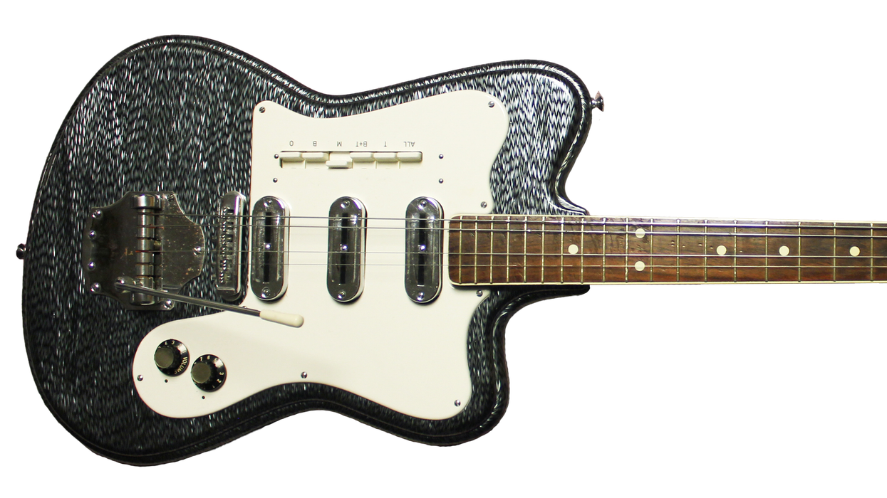
It’s exciting when an unusual project lands on my workbench, and I always welcome the challenge to solve the unexpected problems that inevitably accompany ambitious rebuilds or upgrades. When a guitar has sentimental value to a client—as was the case with this ’74 Epiphone ET-290 Crestwood—I derive extra satisfaction from a successful outcome.
Some background: Our project guitar is a mid-1970s Japanese Epiphone that was given to the owner by his father, who worked for Norlin Music Corp. at the time. Norlin owned Gibson back then and the Crestwood was one of the models Norlin imported from Japan to round out the Gibson and Epiphone lines. A double-cutaway slab solidbody with dual humbuckers and a bolt-on maple neck, the Crestwood blends elements of an SG and a Strat.
My client played this guitar in his first band, but since then it had languished in the closet for decades. It was time, the owner felt, to bring the Epi back into service, and he was willing to invest in the requisite electronics and hardware to make it stage- and studio-worthy.
of an SG and a Strat.
He also had a crazy idea: Add a Bigsby. Until recently, this would have meant drilling holes into the body—a permanent mod I wasn’t keen on doing. But a new product called the Vibramate ($65 street) seemed like it might allow me to install a B5 Bigsby ($168 street) on this Crestwood without drilling any new holes. I was intrigued and we decided to give it a shot. More on this in a moment.
Other planned upgrades included swapping out the stock pickups for a pair of Seymour Duncan Seth Lovers (each $104 street), installing new volume and tone pots, making a new bone nut, and replacing the Tune-o-matic-style bridge, 3-way switch, and output jack.
The owner also wanted to upgrade the tuners, which were not original. The budget keys on the headstock wouldn’t hold their tune and had to be replaced for the guitar to be playable. However, I knew installing pro-quality tuners would require drilling new screw holes and reaming out the post holes. Although the owner wanted to avoid mods that couldn’t be reversed, he felt this was one exception he’d be willing to make.
In the past someone had redrilled the back of the headstock to install the cheap replacement tuners—meaning there were multiple screw holes—so in a sense, the damage had already been done. And as the owner pointed out, it’s not like this Crestwood was a ’59 Les Paul—a sacred relic that couldn’t be touched. So we agreed that since our goal was to bring the guitar back into service, we’d do whatever was required to install better tuners.
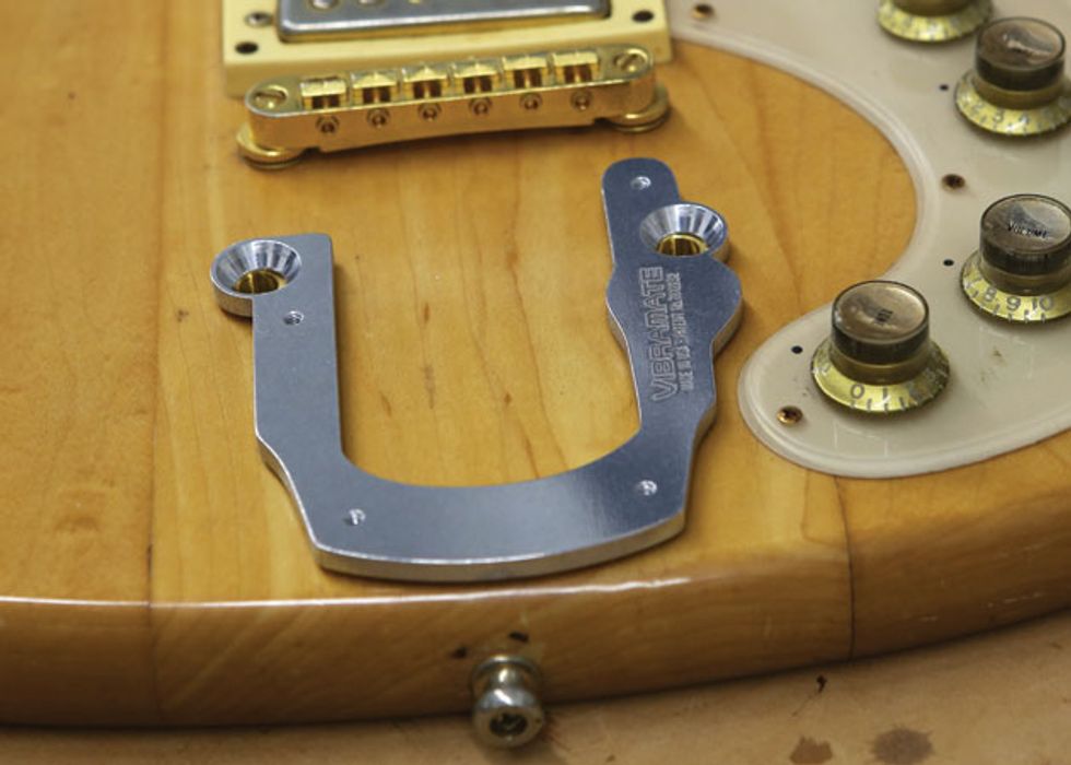
Fig. 1. Checking the fit: The aluminum Vibramate mounts to the original stop-tailpiece stud bushings.
Betting on the Bigsby. First I wanted to answer a burning question: Could we install a B5 Bigsby on this guitar? A sturdy aircraft-grade aluminum plate that replaces the stop tailpiece, the Vibramate sits on the face of the guitar and attaches with studs that thread into the existing bushings. The Crestwood’s large pickguard curves almost behind the stop tailpiece, and because we didn’t want to alter the pickguard, I wasn’t sure we’d have enough room to accommodate the Vibramate plate. Amazing! It fit just fine (Fig. 1). So far, so good.
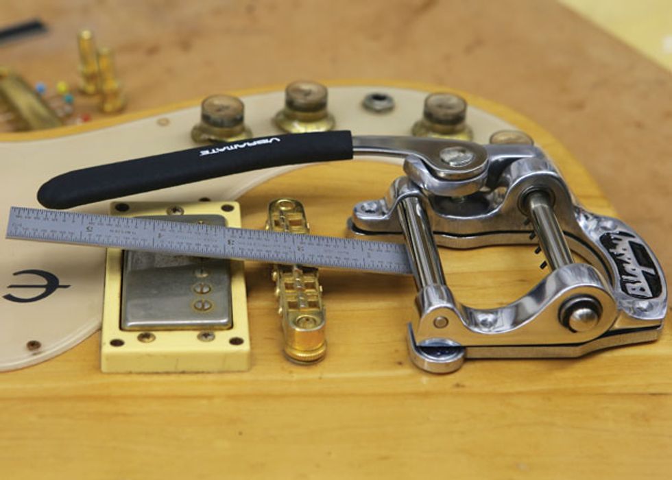
Fig. 2. Confirming the string-break angle before installing the Vibramate and Bigsby.
But before I declared victory and actually installed the B5 Bigsby, I needed to set it on the Vibramate and observe the strings’ break angle as they passed under the rollerbar and up to the bridge saddles. This break angle is important because if it’s too shallow, the strings rattle and lift off the saddles when they’re plucked. Using a 6" precision metal ruler as a guide, I determined the angle was sufficiently steep (Fig. 2). Had it been too shallow, I would have had to reset the neck angle using a full-pocket shim—a big job.
To learn how to make a full-pocket shim, search for “Guitar Shop 101: How to Shim a Bolt-On Neck” at premierguitar.com.
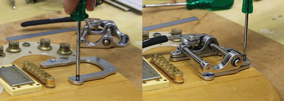
Fig. 3. (left) Mounting the Vibramate. Fig. 4. (right) Mounting the Bigsby to the Vibramate. No drilling required, so it’s a
100% reversible mod.
Now I could confidently mount the Vibramate (Fig. 3) and B5 Bigsby (Fig. 4). The Vibramate’s two stud screws come in both U.S. and metric threads, and I used the latter to attach the plate to the existing stud holes. Then using the four supplied machine screws, I secured the Bigsby to the Vibramate.
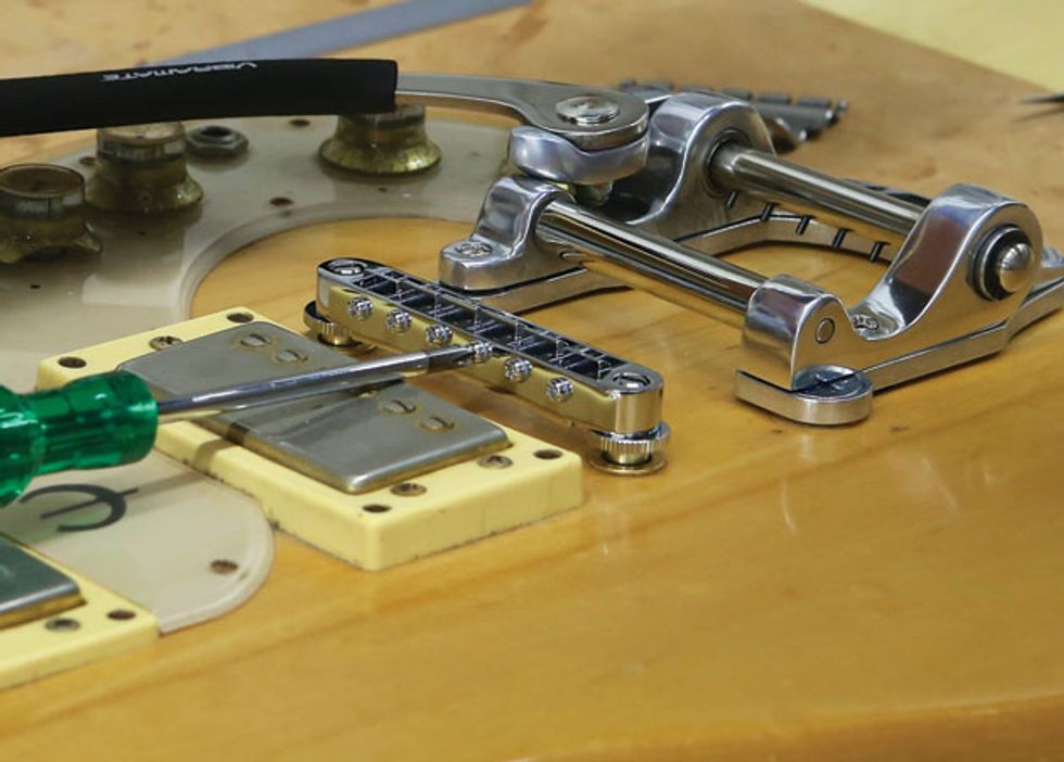
Fig. 5. Installing the Tune-o-matic-style bridge with the saddle intonation screws facing forward.
Once the Bigsby was attached, I removed the old bridge and posts and replaced them with a new system ($40 from Allparts). Knowing the Bigsby rollerbar would make it hard to access the intonation adjustment screws from the rear of the saddle, I faced it forward (Fig. 5).
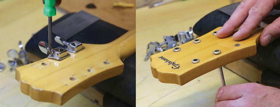
Fig. 6. (left) Removing the cheap tuners that had obviously replaced the original set. Fig. 7. (right) Pushing out the old bushings with the handle of an X-Acto knife.
Installing the tuners. This turned out to be trickier than I’d anticipated, and we almost had to halt the project here. After carefully unscrewing the old tuners (Fig. 6), I removed their press-fit bushings from the face of the headstock using the handle of a small X-Acto knife. Pressing the rounded end through the post hole and gently applying pressure to the bushings (Fig. 7), I was able to coax them out without damaging the finish around them.
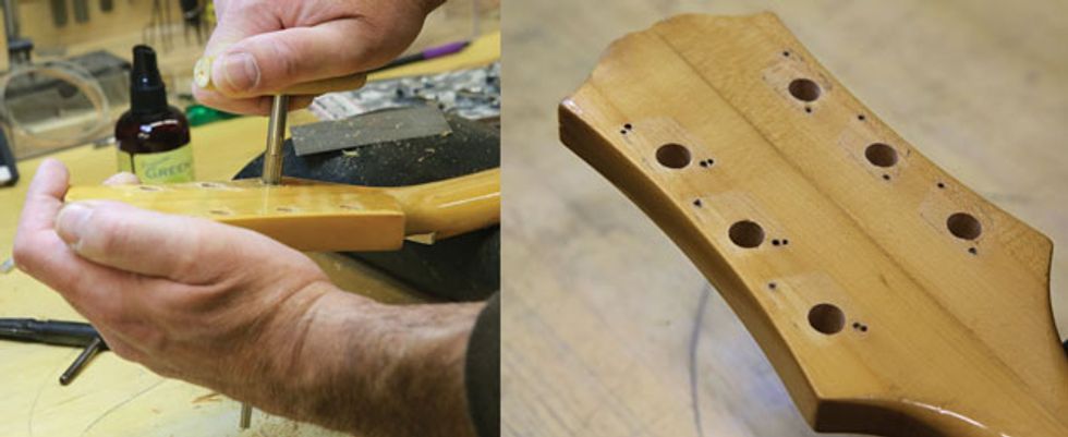
Fig. 8. (right) Carefully enlarging the tuner holes with a Stewart-MacDonald Peghole Reamer to accept the new 16:1 Gotoh tuners. Fig. 9. (left) The specialized headstock reamer leaves clean, round holes that are tough to achieve with hardware-store reamers.
We chose to install a high-quality set of Gotoh tuning keys ($55 street from Allparts). These Gotohs have a 16:1 turning ratio and are very well machined, but for the keys to fit properly I had to ream out the holes on the back of the headstock (Fig. 8). Again, it’s not something I’d do to a valuable vintage guitar, but in this instance I had the owner’s blessing. I used a specialized peghole reamer from stewmac.com that cuts cleaner, rounder holes (Fig. 9) than reamers you’d find at the hardware store. In this photo you can clearly see that different sets of tuners had previously been installed on this Epi.
Tip: A reamer is the correct tool to use for enlarging a tuner hole. You can work slowly and carefully and you won’t split the headstock like you might with a power drill.
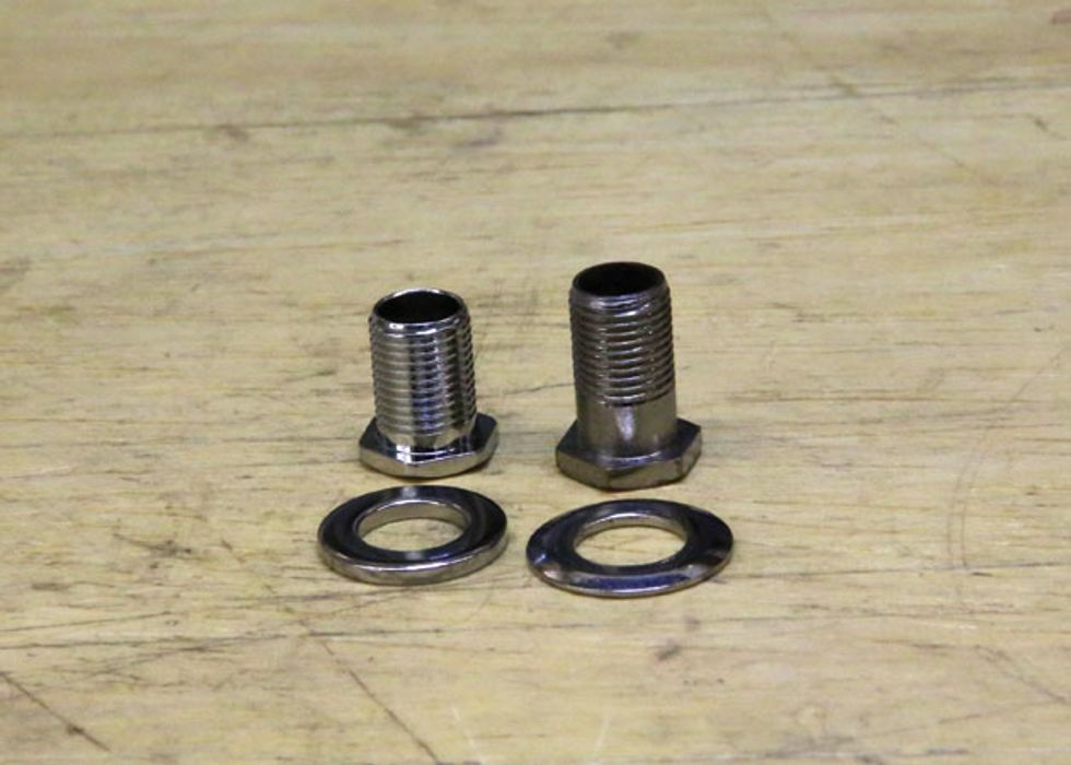
Fig. 10. Yikes! The Gotoh threaded collar (left) is too short to reach its tuning machine through the headstock. Fortunately, taller collars and thinner washers (right) pirated from another set of tuners fit through the headstock and match the Gotoh threads. A close call.
Here’s where the project almost went off the rails. After I’d fitted the tuners into their snug, new holes and pushed them through the headstock, I was dismayed to discover that the supplied threaded collars were too short to reach the matching threads in the keys themselves. These collars secure the tuners to the headstock, so they’re essential. The problem? The Epi’s headstock was thicker than a typical Strat-style guitar. Fortunately, I found a set of longer collars (Fig. 10) I could pirate from another set of keys in my shop. We got lucky this time.
Tip: Always measure the thickness of the headstock before you purchase tuners.
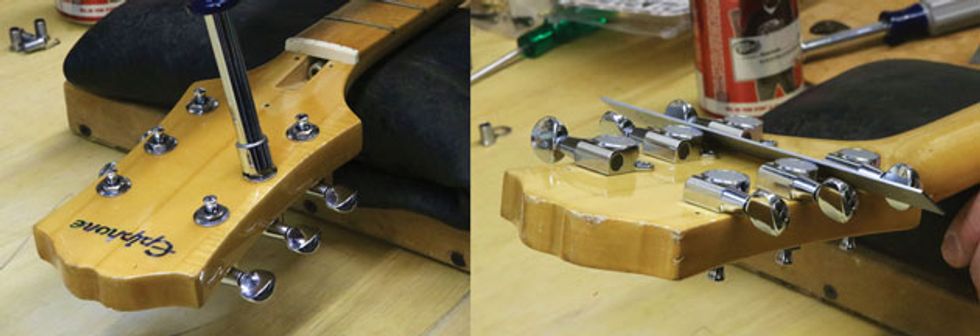
Fig. 11. (left) To avoid marring the collar nut or headstock, always use a socket wrench—not an adjustable wrench—to install this type of tuner. Fig. 12. (right) Use a metal ruler to align the tuners with each other on the headstock.
Using a socket wrench, I installed the Gotoh tuners (Fig. 11). Don’t do this with an adjustable crescent wrench because it’s likely to slip off and butcher the nut or mar the headstock.With the collars moderately tight—but not completely torqued down—I then worked on aligning the tuners with each other. Once again, a 6" metal ruler comes in handy (Fig. 12).
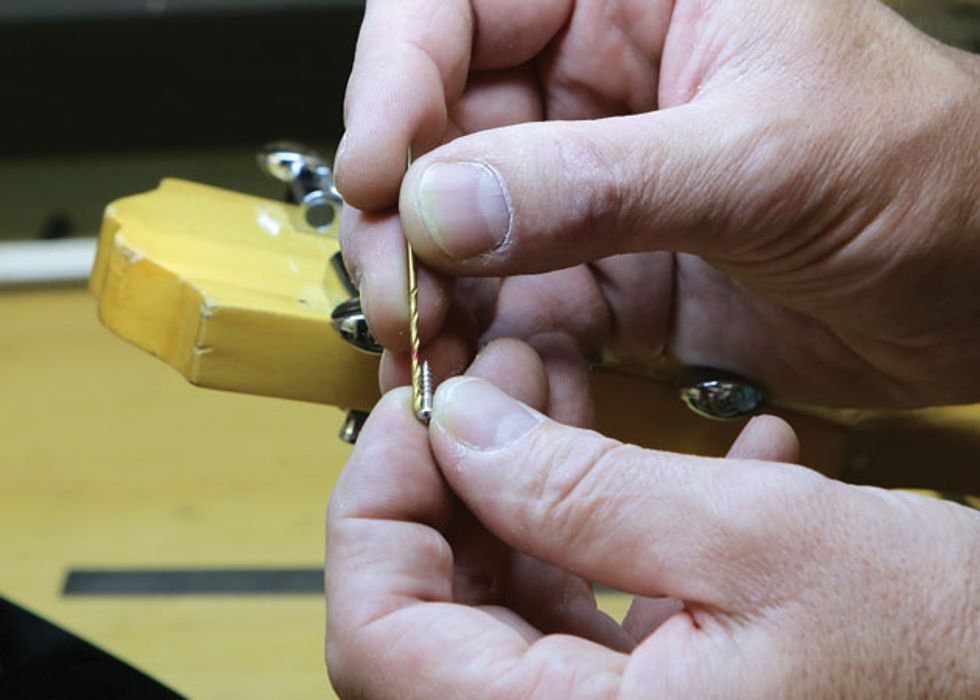
Fig. 13. Measuring the drill bit against the tuner mounting screw. Once you’ve found the correct drill bit, mark the drill depth with a red Sharpie.
With the tuners now aligned and tightened against the headstock, it was time to drill holes for the tuner mounting screws. You must do this very carefully. For starters, use a drill bit that’s the same size as the screw shaft (Fig. 13). This leaves enough room for the screw threads to “tap” into the wood without splitting the headstock. If you drill the screw holes too small, inserting the screws can cause the headstock to crack. Never force the screws into the headstock.
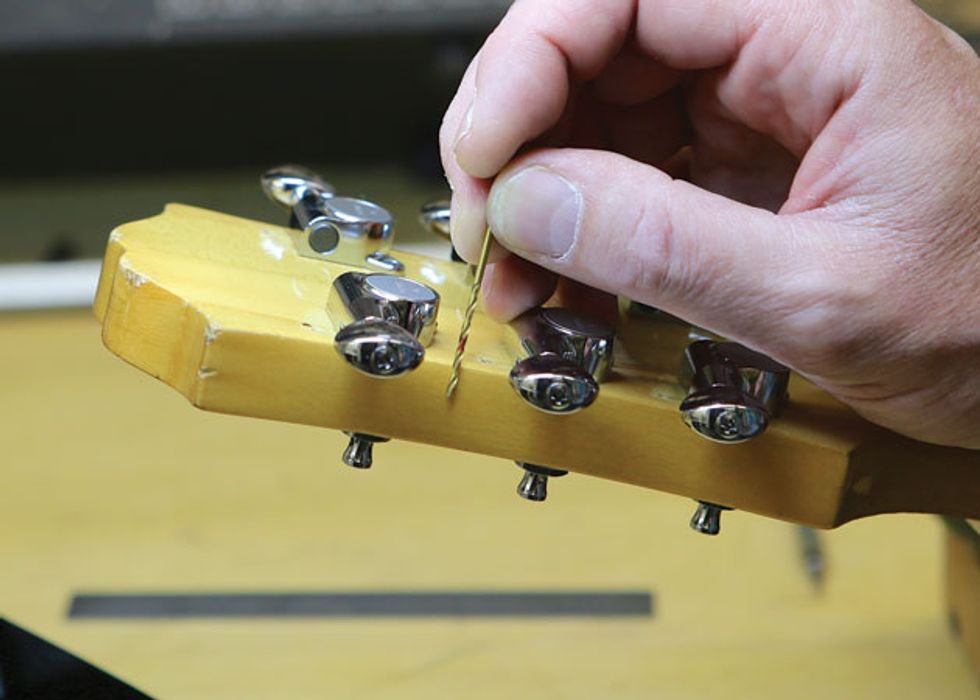
Fig. 14. Confirming bit depth with the red guide mark. Remember to take the tuner’s screw eyelet
into account when measuring.
Here’s another trade secret: Mark the drill bit with a red Sharpie to illustrate the correct depth for the mounting holes, as shown in Fig. 13. Before drilling any holes, place the bit against the headstock. While taking into account the thickness of the eyelet that holds the mounting screw, determine how far the screw will penetrate the headstock (Fig. 14). The last thing you want to do is drill through the headstock!
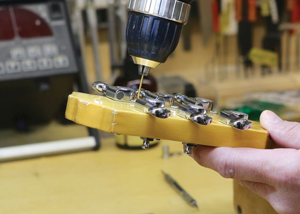
Fig. 15. Carefully drilling holes for the tuner mounting screws. Always support the headstock and work slowly, checking the red depth mark as you drill.
Once I’d double-checked the drill bit depth, I slowly drilled the tuner screw holes while watching the red guide mark like a hawk (Fig. 15). Always support the headstock to keep it steady and above all, take your time.
Diving inside. In addition to the Seth Lovers, the owner specified all new electronics, so I planned to install Bourns potentiometers (two 500k volume and two 250k tone, each at $17 street) and a short Switchcraft 3-way toggle switch ($23 street). A Switchcraft output jack and a pair of .047 µF capacitors for the tone controls completed the package. We’d already decided to use the ’50s Les Paul wiring for the tone pots, so I was set to go.
For details on the ’50s LP wiring, visit premierguitar.com and search for “The Fabulous Four: Mods for your Strat, Tele, Les Paul, and “Super Strat.”
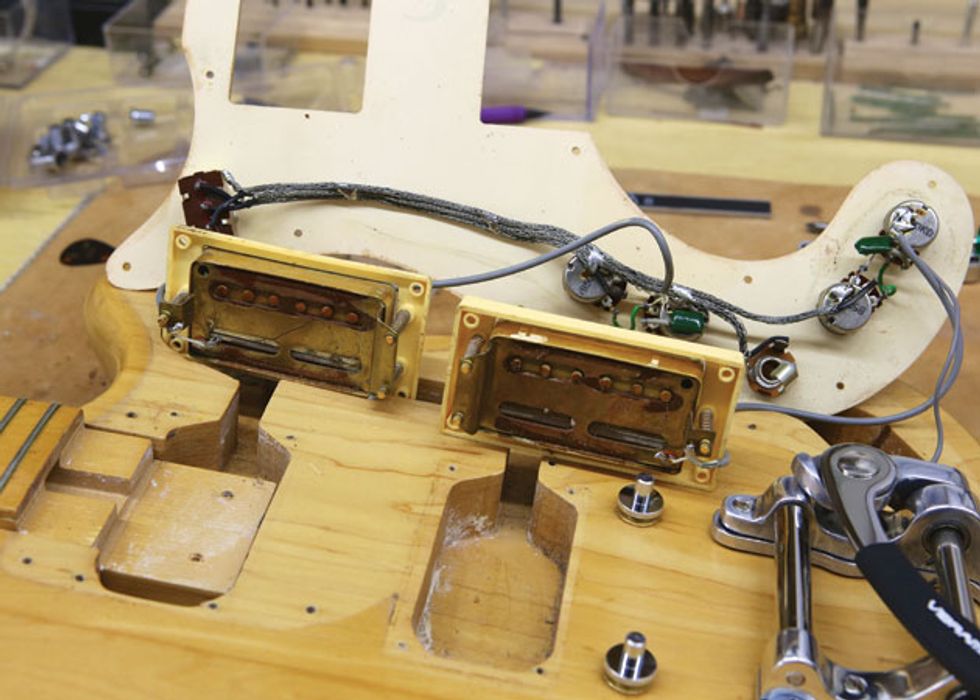
Fig. 16. Surprise! Part of the neck extends into the neck pickup cavity, making it very shallow.
Unscrewing the pickguard and pickup mounting rings allowed me to examine the wiring harness and original pickups to get a sense of what work lay ahead. If you study Fig. 16 carefully, you’ll notice two things: First, part of the neck extends into the neck pickup cavity. Second, the original pickups had a single height adjustment screw on the treble side, but two height adjustments screws on the bass side. Okay, two problems to solve.
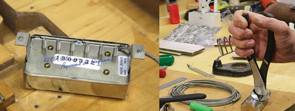
Fig. 17. (left) A stock Duncan Seth Lover humbucker has long pole piece screws. This neck pickup isn’t going to fit in the Crestwood. Fig. 18. (right) Ah—there is a solution. Carefully trimming the pole pieces with a diagonal cutter allows the pickup to fit in the cavity with enough room for height adjustment.
Fig. 17 shows the underside of the Lover neck humbucker, complete with signatures and serial number. The long pole pieces prevented the pickup from dropping down into the cavity. I knew I wasn’t going to start routing out wood from this guitar, and that left just one alternative: trim the pole pieces. Using a pair of dikes, I carefully snipped off the pole pieces close to the baseplate (Fig. 18). Now the pickup could fit into the cavity with enough room to adjust its height.
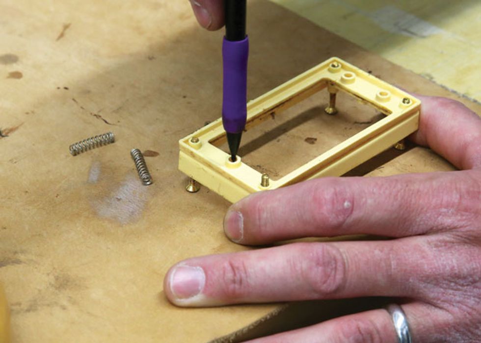
Fig. 19. Using the original pickup rings to make a temporary jig for marking centered mounting-screw holes.
Normally I’d replace the pickup mounting rings with new rings that matched the Lovers’ mounting brackets, but the original Epi rings were much larger than modern ones and they nestled snugly into the pickguard. Modern rings would have left an ugly gap, so we had to keep the old rings. As much as I hated to modify them, I had little choice but drill a center hole into the bass side of each ring. I temporarily attached the original rings to each other, which gave me a jig to mark the new screw holes (Fig. 19).
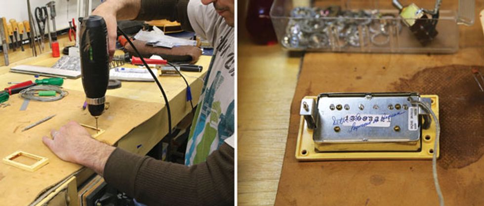
Fig. 20. (left) Drilling the new centered holes in the old mounting rings. Always scribe a mark and then make a pilot hole before drilling into soft plastic. Fig. 21. (left) The neck pickup mounted in the original ring.
Note the trimmed pole piece screws.
Using the mark as a guide, I scribed a pilot hole, then reverse-drilled a deeper pilot hole, and finally drilled a new hole in each ring to accommodate the Lovers (Fig. 20). (Fig. 21) shows the neck Lover mounted in the original Epi ring. Note the trimmed pole pieces.
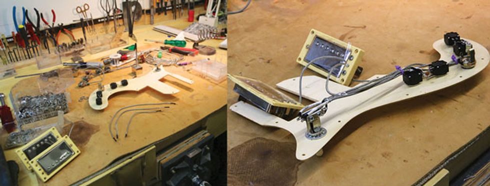
Fig. 22. (left) Bourns pots and Switchcraft jack and 3-way toggle are mounted on the pickguard, the harness wires are cut and tinned, and the pickups are mounted in their rings. Time to wire this baby up. Fig. 23. (right) Everything is now wired on the pickguard. Cable ties keep the harness neat so the pickguard will easily fit onto the cavity.
Firing up the soldering iron. Next I mounted the pots, toggle switch, and output jack to the pickguard, and then cut and tinned new harness wires using braided shield wire with a cloth core jacket (Fig. 22). When I was done wiring all the electronics, I added a couple of cable ties to keep everything neat and compact, and also inserted a pair of screws to each pickup ring to fill the empty, unused holes (Fig. 23). The latter was strictly a cosmetic decision, but such little details can make a big difference.
I connected the bridge ground wire to the harness, and after testing the electronics to confirm everything was working properly, I used new screws to attach the wired pickguard to the body.
Replacing the string nut. The original bone nut wasn’t too bad, but the bass strings sat too low and the overall string spacing was just a little off. I found a nice piece of bone stock and carved a new string nut. I shaped the nut blank to fit the nut slot, and marked it with a pencil to determine how much material to remove from the top. Next, I used my belt sander to remove the excess material and then contoured the nut top with a radius block and fine self-adhesive sandpaper. With the nut blank shaped and ends trimmed, I measured out the string spacing and began to carve the string slots.
For a detailed description of the nut carving process, along with photos illustrating every step, visit premierguitar.com and read “DIY: How to Convert a Flattop to Nashville Tuning.”
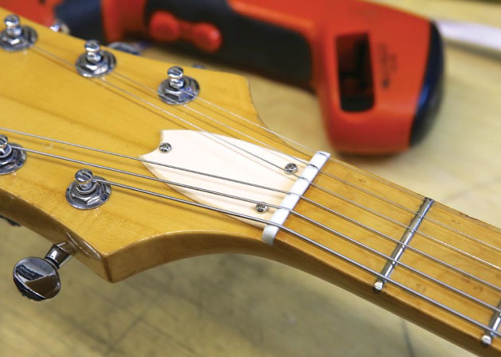
Fig. 24. The finished bone nut. Graphite from a mechanical pencil provides dry lubrication for the string slots.
When I had the slot depth, string spacing, and string exit angles where I wanted them, I polished the nut and colored the slots with a mechanical pencil for lubrication. Then I strung up the guitar with a D’Addario EXL110 set (.010–.046), which is what the owner requested, and gave the nut a final check (Fig. 24).
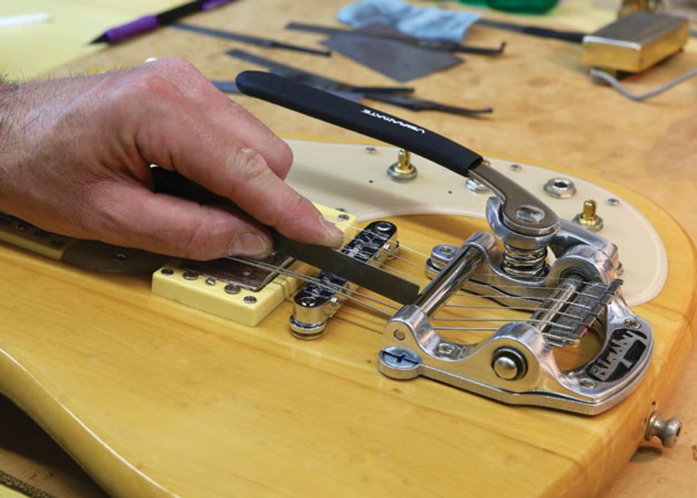
Fig. 25. Notching the bridge saddles with gauged nut files. Notice how the strings attach to the Bigsby with the Vibramate String Spoiler—a real time-saver compared to the traditional “curl strings over and under the bar” method.
Notching the saddle. Next I turned my attention to spacing the strings on the Tune-o-matic-style bridge and notching its saddles (Fig. 25). This involves filing a small, shallow channel in each saddle to hold the string and prevent it from shifting when you pluck it. I use gauged nut files to match the different string widths in the owner’s .010 set.
Some considerations: It’s important to have all the strings an equal distance from each other, as well as the 6th and 1st strings placed equally in from the edge of the fretboard. Ideally, you also want the strings sitting over the center of the pickup pole pieces.
Unfortunately, this isn’t always possible. It’s rare that a pickup’s generic pole-piece spacing perfectly matches the string spacing on a given guitar. Also, the fret ends on one side of the neck may be beveled at a slightly different angle than the other, which means you may have to position the 6th or 1st string further in from the fretboard edge than the other. This is a horror story for those of us with OCD! The trick is to “average” the spacing to compensate for the uncorrectable variables, and this is more art than science.
For more details and photos on string spacing, read “How to Install a New Tune-o-matic Bridge” at premierguitar.com.
You can buy bridges with either pre-notched or un-notched saddles. If there’s one thing I’ve learned about installing Tune-o-matics, it’s that pre-notched saddles never put the string in the correct spot. String alignment can vary dramatically from guitar to guitar, and thus the correct location of the notches can vary too. My advice is to get un-notched saddles and cut your own.
If you look closely at the Bigsby in Fig. 25, you’ll see that the strings are held in a claw-like device by their ball-ends instead of wrapping over and around the second bar to attach to neck-facing pins—the standard Bigsby configuration. This nifty ball-end holder is called the Vibramate String Spoiler ($35 street). Named after the auto spoiler fin, this beautifully machined stainless steel bracket fits on any Bigsby without any modification or tools. It really simplifies stringing up a Bigsby—a huge time saver.
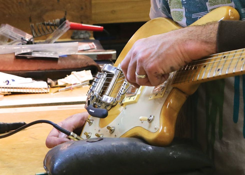
Fig. 26. When installing a Bigsby, face the bridge’s saddle intonation screws toward the pickups.
Final setup. Once the saddles were notched I was ready to do the final setup, which includes adjusting pickup height, neck relief, action, and intonation. You may recall that I turned the intonation screws toward the pickups, rather than the Bigsby, and Fig. 26 illustrates why: You need room to reach the intonation screws with a screwdriver.
For photos and detailed explanations of how to adjust pickup height, neck relief, action, and intonation, visit premierguitar.com and search for “How to Convert Your Axe to a Baritone.”
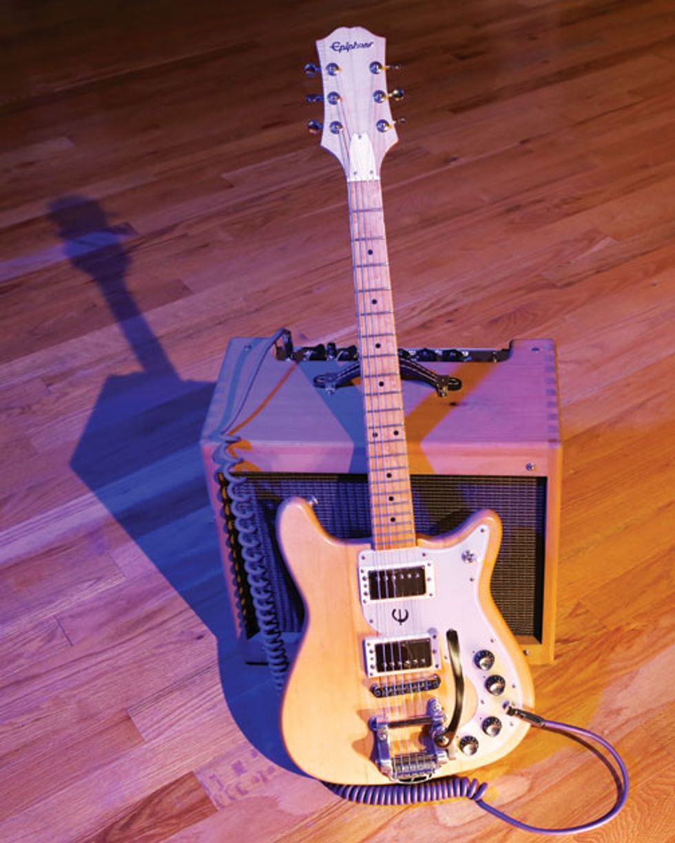
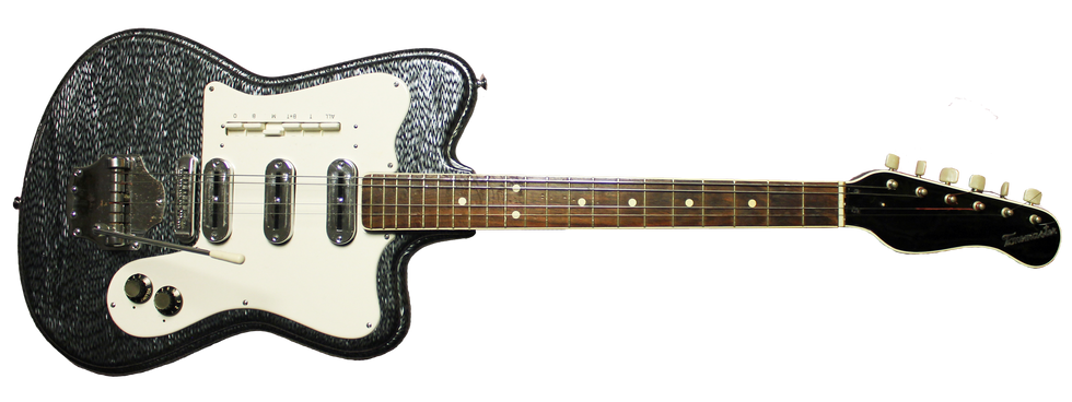
Fig. 27. With its new pickups, electronics, hardware, and bone nut, this Epiphone ET-290 Crestwood is all
dressed up and ready to rock.
Ready to rock. Finally, after many hours of work, this ET-290 Crestwood was ready for prime time (Fig. 27). It sounds amazing and plays beautifully—a tribute to its solid build quality and top-shelf electronics and hardware upgrades. For the owner, who invested a serious chunk of change in this project, the joy of bringing his 40-year-old friend back from retirement was worth the cost. Now transformed from a budget axe to a gig-ready sound machine, this Epi is geared up to provide decades of music-making pleasure.
Watch this “before” and “after” video of the ET-290 Crestwood in action:


 Boyd Holbrook is a fan of “Dueling Banjos.”
Photo by Leo Jacob
Boyd Holbrook is a fan of “Dueling Banjos.”
Photo by Leo Jacob