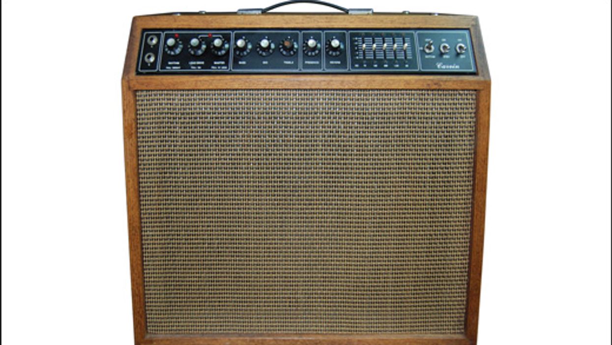
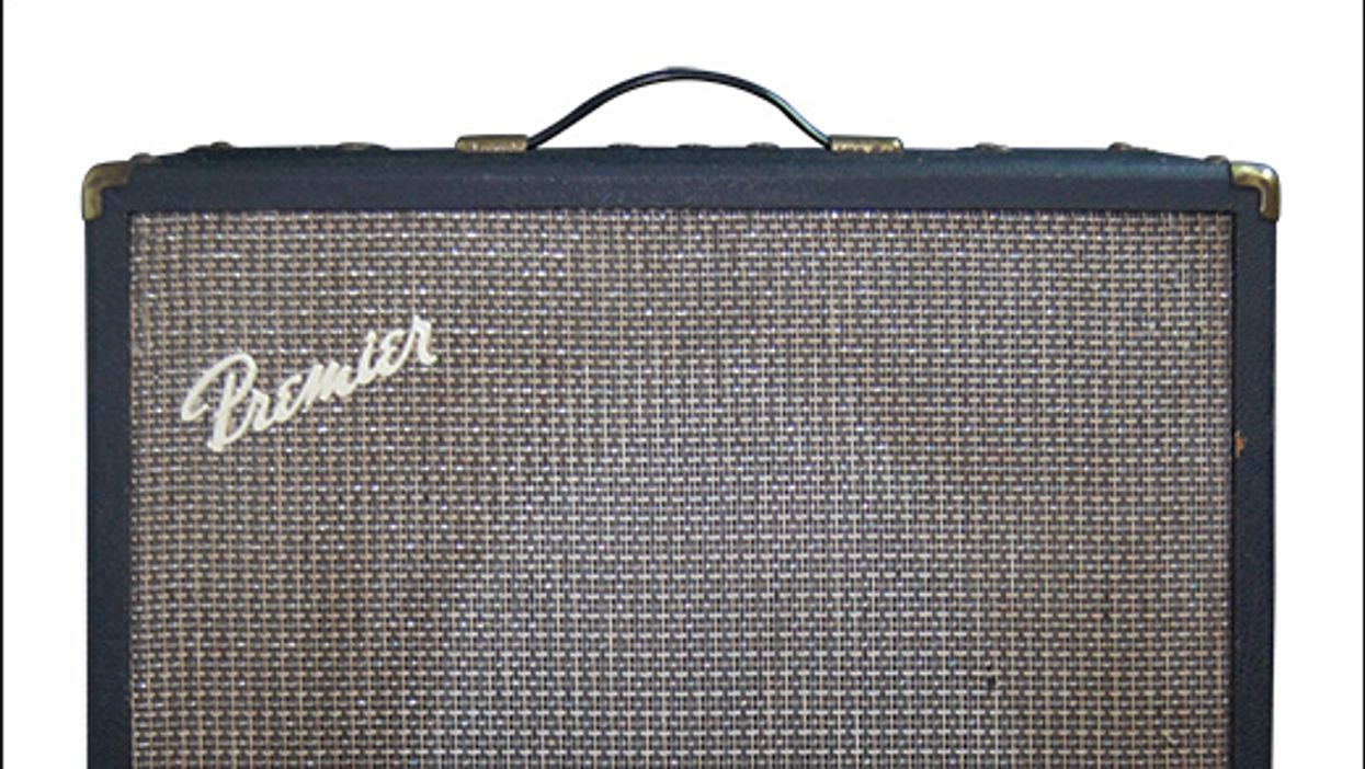
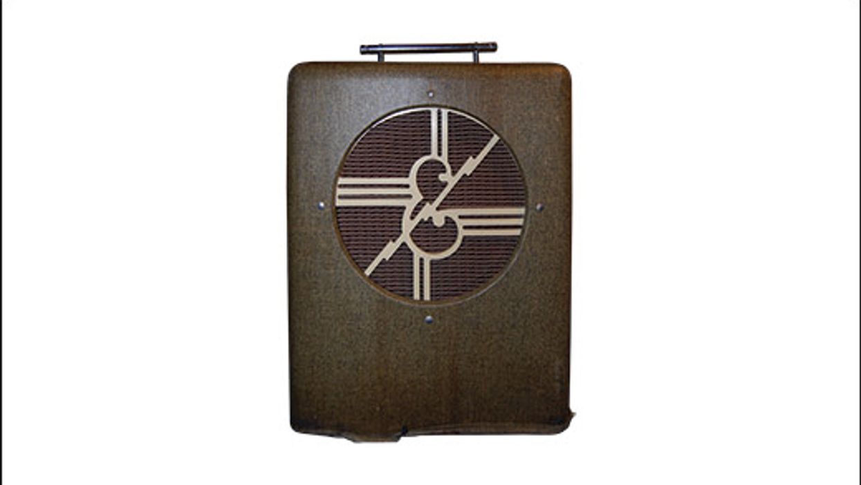
Photo courtesy of Richard’s Gear Bazaar/Reverb
Search
Latest Stories
Start your day right!
Get latest updates and insights delivered to your inbox.

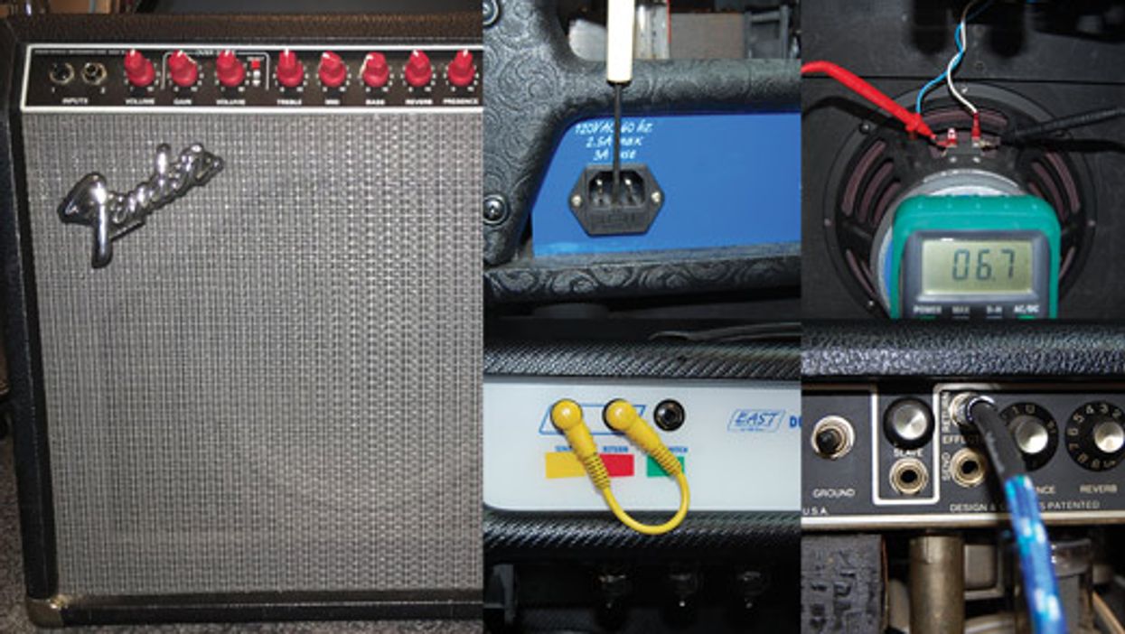
Ask Amp Man
It’s no secret that tube amps require regular TLC to sound their best. But it doesn’t stop there: Tweaking key components can yield dramatic sonic benefits—but you have to know what you’re doing. Whether you’re looking for more gain, higher clean headroom, or simply want to return an old combo or head to its former glory, amp guru Jeff Bober has the answers you’re looking for. Got questions? Shoot him an email at pgampman@gmail.com.

Don’t Miss Out
Get the latest updates and insights delivered to your inbox.
Popular
Recent
load more