Hello Amp Man readers. This month I’ve picked two interesting questions, and since the first references a Fender Super Reverb, I’m going to answer both based on that amp. So read on!
Question #1
Dear Amp Man,
I’ve been maintaining and modifying my meager amp collection for a few years and studying amp technology/topology. You know … for fun. (Who doesn’t have a folder of Fender schematics near the john?)
One aspect of modern amp design that I don’t understand is the headphone out—especially with respect to the load (the output not “seeing” the amp’s speaker). How does it work? Is it something that can be added to an amp? Would I want a wire connecting a Super Reverb and my ears?
Cheers,
Bill Fugate
Okay, let’s get started with question #1. As far as “would I want a wire connected between a Super Reverb and my ears?” Well, that’s for you to decide, but if you choose “yes,” here’s how to do it.
Fig. 1 is a simple circuit I came up with to allow you to play your amp through your headphones without waking the kids or disturbing your neighbors at 2 a.m. So you can understand what’s happening, I’ll go through it and describe the function of each component.
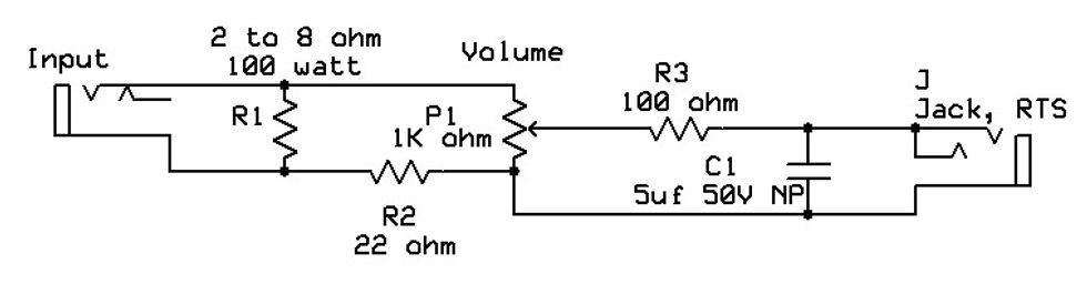
Fig. 1: This diagram illustrates the modifications required to add a headphone out to a Fender Super Reverb.
Jack 1 is the input from your amplifier’s speaker output, at left in Fig. 1. The resistance value should be as close to the output impedance of your amp as possible. For a Super Reverb, that would be 2 ohms. If it’s not possible to get the exact resistance, it’s okay to go up in value, but not down. This resistor will be replacing the speakers in your amp, which need to be disconnected, so it will be absorbing your amp’s full output power. I recommend that the resistor’s power-handling capability be at least double your amp’s output power. A Super is rated at about 40 to 45 watts, so I recommend at least a 100-watt resistor here. Also, if you’re using the large, gold anodized aluminum resistors, they get very hot and need to be mounted to properly dissipate the heat. If you’re building this inside a Bud box or something similar, mount the resistor to the box and be sure to install feet on the bottom of the box so that the heat doesn’t damage what the box is sitting on—like possibly your amplifier. It would also be a good idea to vent the box.
Next, the signal goes to the volume pot. A 1k-ohm, half-watt or higher, linear pot works fine here. A 22-ohm 1-watt resistor gets connected to the pot’s counter-clockwise arm to provide a little isolation from the amp chassis and add a bit of a signal drop.
Then the signal from the pot’s wiper gets connected to the headphone output jack through a 100-ohm resistor. For testing, I used a set of Tascam headphones with a 32-ohm impedance, which is pretty standard today, and the 100-ohm resistor worked fine and provided plenty of volume. If you need a bit more level, decrease the value of this resistor. Also, the output jack should be insulated from the chassis because we’re trying to maintain a bit of isolation from input to output. A typical “British-style” jack works fine here. Just make sure it’s stereo and don’t forget to connect the tip and ring connections together. The last component you see is a 5 µF 50V non-polarized cap. Since a resistive load on an amplifier causes it to react differently from a speaker load, amps tend to sound more “spiky” with a resistive load, so this capacitor helps smooth out some of the brittleness of the sound in the headphones.
There you have it—a way to play your amp silently.
Question #2
Dear Premier Guitar,
I’ve grown to appreciate your DIY pieces, and they’re well written to the targeted reader. I would like to get your take on the possibility of using the reverb “send and return” loop as an effects loop. It seems easy: An adapter cable changes the RCA plugs to 1/4". The cables go to your effects pedals and return, instead of the reverb can. The cool part is the reverb control would now mix the wet and dry signals. Will this work? Can you use “Y” cables and a switch to include the reverb as well? Are the impedances so far out to lunch that it’ll never work? Is that why I’ve never heard of anyone doing this?
Wysong Perabula
Question #2 asks about the possibility of using the amp’s reverb circuitry as an effects loop. In essence, it already is an effects loop, but it’s optimized for use with the reverb tank, which is far different from an effects pedal. We can, however, get it to work as a pedal loop.
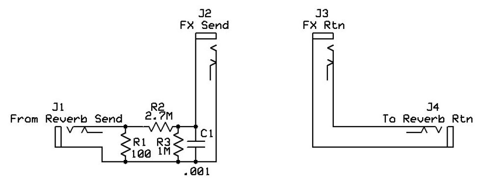
Fig. 2: This schematic shows how a reverb circuit can be turned into an effects loop. Unfortunately, it’s at the price of the reverb—but there are pedals for that.
The biggest difference between a normal effects loop and a reverb circuit is basically in the “send” department. A typical Fender-style reverb tank has very low input impedance, and this requires a substantial level to drive it. This level is far too hot to feed into any effects pedal, so we must first tame the beast. Looking at Fig. 2, R1 serves as a load on the reverb drive transformer. Next R2 and R3 form a voltage divider to reduce the signal to an acceptable level for an effects device. Since the reverb drive circuit is actually a small amplifier output stage using its own little output transformer, removing the inductive load from the reverb tank and replacing it with the 100-ohm resistive load is similar to removing the speaker load from an amplifier and replacing it with a resistive load. Things get a little “spiky.” To compensate for this, we add the .001 µF capacitor—identified as C1—to smooth out the sound.
Now we have a signal that will be a better match for a pedal. Regarding the effects return, the effects can be connected directly to the reverb return (out) of the amplifier, either by 1/4" to RCA cable or, if you’d like to contain this all in a project box, simply connect the loop return jack directly to the reverb return jack, as most pedals should be able to comfortably drive its 220k input impedance. The loop can now be used for your time-based effects (delay, reverb, chorus, flange, phase, etc.). The reverb knob will mix in the amount of effect, so set your effects for 100 percent wet, if possible, to minimize any phase cancellation problems. The footswitch will now turn the effects on and off as well. As far as including the reverb tank back into the circuit, the output impedance is too low and would more than likely attenuate the output of the effects devices.
Well, there you have it. Enjoy the experimentation!