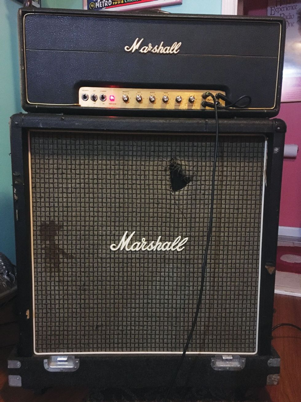
A higher feedback resistor value is among the design aspects that make an old-school Marshall amp have more grit or grind than an old-school Fender.
Hi Jeff, First, I want to tell you how much I enjoy your articles. I’m not a technician, but I enjoy learning about electronics and amplifiers, because it‘s helpful to know your gear and tonal options. For example, regarding your column about the Fender DRRI [“Beefing Up a Fender Deluxe Reverb Reissue,” December 2017], I have a couple of follow-up questions for you:
- 1) I have a 1976 silverface Fender Deluxe Reverb (a pre-volume boost model) and obviously, it’s handwired versus the circuit-board construction of the DRRI. If I were to do your tone mod to my amp’s vibrato channel, would you still recommend the same values for the bass and mid capacitors in the tone stack?
- 2) Is it possible for me to add reverb to the normal channel without adding tremolo? Or is it “all or none?” (I would rather not add tremolo, if possible.)
- 3) To give the amp more of a Marshall flavor, what are your thoughts about removing the negative feedback loop? Is this effective or do you think the Deluxe Reverb needs a certain amount of negative feedback? I've heard this would increase the amp’s midrange aggressiveness, but I'm afraid it might make the amp too bright. (Maybe add a switch for this function?)
Mark Hunter
Lebanon, Ohio
Hi Mark,
Thanks for reading my columns, and I’m glad you can appreciate them from an “options” perspective. As I’ve told players over the years: You don’t need to know everything about how it works; you just need to be happy with it. That said, let me try to answer your questions, although it will be technical at times. Let’s get started.
No. 1. The answer here is “yes.” The type of construction does not dictate the values of the capacitors in the tone stack. Although there may need to be some changes, deletions, or additions of smaller capacitor values in one type of construction verses another in some amps, these suggested values (2x 0.022 µF in this instance) would remain the same.
No. 2. The answer here is, unfortunately, “no.” The vibrato (tremolo) circuitry is actually post-reverb circuitry, so once the signal from the normal channel is routed into the reverb circuit, the subsequent tremolo circuit will affect both channels. Sorry, but as with most changes (modifications, improvements, etc.) in an amp, there’s generally some degree of trade-off somewhere.
No 3. My initial answer here is “no,” I wouldn’t recommend removing the negative feedback loop. However, we certainly can change the negative feedback loop in a few different ways, so let’s have some fun with this one!
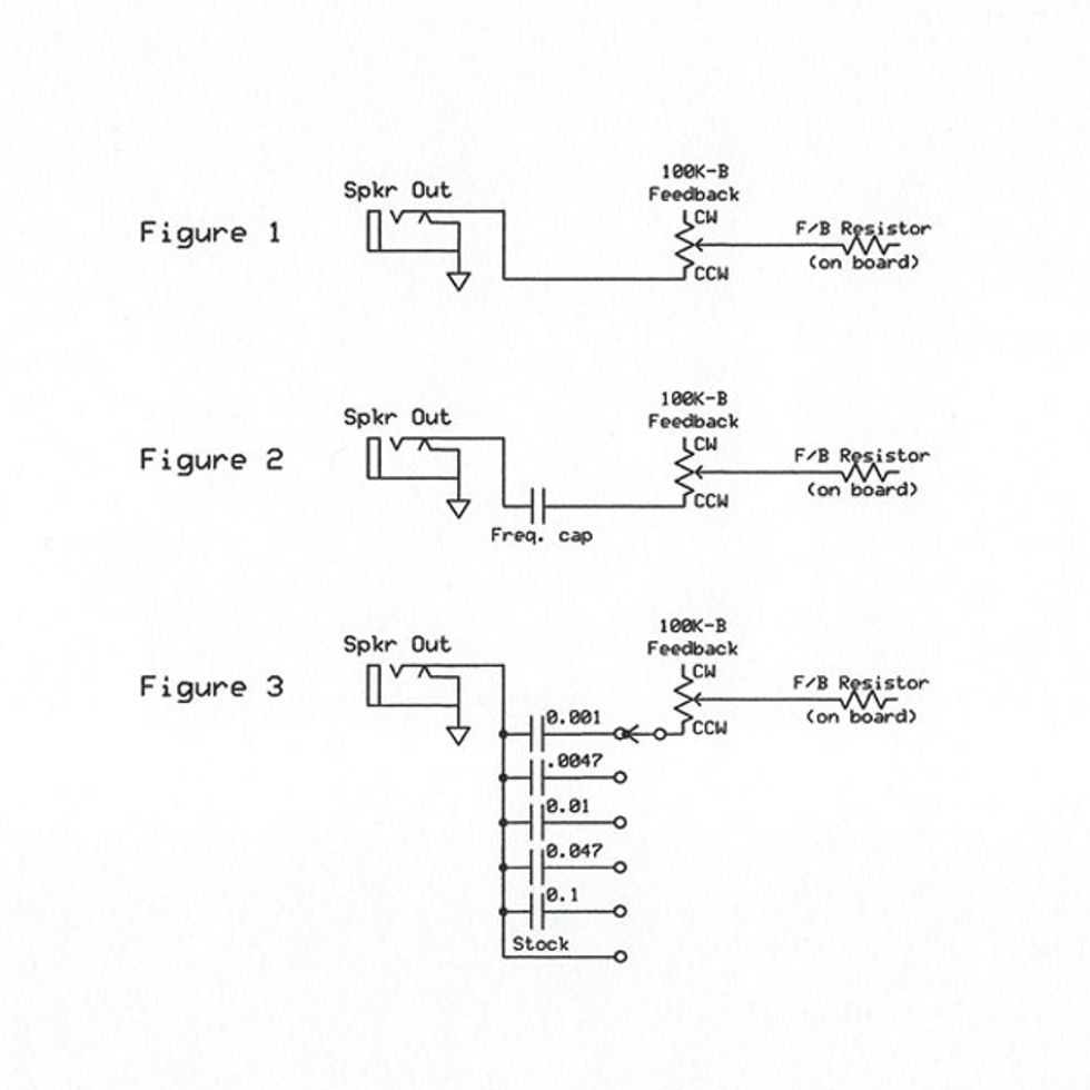
This drawing illustrates all three wiring options Amp Man suggests for modifying a Fender’s negative feedback loop to create more control and alter tone.
First, let’s have a very broad look at what negative feedback actually is. In a nutshell, negative feedback is incorporated in an amp design as a way to minimize distortion in the output stage of an amplifier. This is done by sending an out-of-phase signal into the phase inverter circuit, reducing its gain and, thereby, distortion. This is especially important in hi-fi amps to reduce THD (total harmonic distortion) and possibly other types of distortion as well. But hey, we’re guitarists…. We like distortion. Maybe not in every situation, but at least when one is “rocking out,” as the hipsters say. (Ha-ha!)
So, why not just remove all the negative feedback from your Deluxe Reverb? Well, you certainly can do that, but I find the result to be a bit too “woolly” or uncontrolled for my taste. If we take a look at the feedback resistor in a typical Fender-style amp, we would generally find a value of 820 ohms. Now, looking at a vintage Marshall, we’d find a 47k or 100k ohm value.
WARNING:
All tube amplifiers contain lethal voltages. The most dangerous voltages are stored in electrolytic capacitors, even after the amp has been unplugged from the wall. Before you touch anything inside the amp chassis, it’s imperative that these capacitors are discharged. If you are unsure of this procedure, consult your local amp tech.Definitely a large difference in value, and although there are other aspects of the design that come into play, this is why an old school non-master 50- or 100-watt Marshall amp tends to have more “grit” or “grind” than an old school 40- or 80-watt Fender.
So what do we do? Let’s make the feedback variable. I’ve done this mod to many Fender amps—especially in the early days of my career. It’s a very simple mod I used to call an “output response control.” I would remove the external speaker jack from the rear of a Fender amp, install a 100k pot, remove the feedback lead from the output jack “hot” lug, connect it to the wiper of the pot, and connect a short lead from the CCW lug of the pot back to the hot lug of the output jack. (You can see the schematic for this in Fig. 1.) That’s it! Now you have a variable feedback signal that can go from a stock setting (CCW) to far less feedback, yielding a more aggressive-sounding output stage. Okay, that’s cool—but what if we can tailor the response even further? Let’s examine.
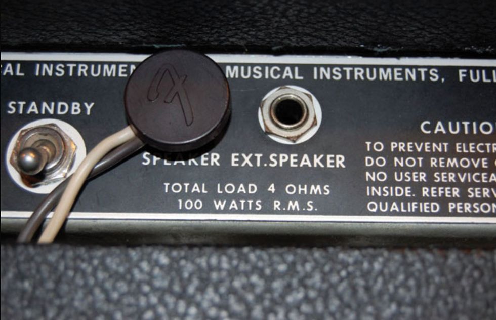
Removing the external speaker output is the first step in making a Fender amp’s negative feedback loop variable.
With the current setup, the signal from the output stage is fed back equally over the full frequency range of the amp, thereby reducing the gain over the entire frequency range. But what if we could be selective about the frequency range? Well, we can, if we add a capacitor in series with the resistor. This will begin to reduce the amount of low frequency signal that is fed back. (See Fig. 2.) The smaller the capacitor value, the less low frequency is fed back. This way we can reduce the gain of the higher frequencies while keeping the low end more full. You can experiment with different capacitor values here, and don’t be too concerned about the voltage rating of the caps. Anything with a 25V or greater rating should work fine.
Start with maybe a 0.1 µF cap and go smaller from there: 0.047, 0.022, 0.01, 0.0047, and all the way to a 0.001 µF. You could also use this cap in place of the small jumper wire that connects the pot to the output jack “hot.” That way both leads are solidly attached. If you want to get more creative, you could even use a multi-position rotary switch to be able to select between values (Fig. 3). If you decide to install both (and drill a hole in your amp), you would then have full control over the frequency and level of your feedback loop.
So Mark, now you can enjoy frequency selectable feedback!