Dear Amp Man,
I am unable to find anything on cascading the half-unused tube in an AA371 Bassman. I have converted the amp to a Marshall tone stack and other suggestions you've made very successfully, but found nothing on tapping into the unused gain stage for the bass side. I've left the normal channel mostly stock and really want more gain on the modded side. The article you wrote on the Supro (“Modding a Supro 6420 Thunderbolt") got me inspired to try this. I've been looking for a layout over a schematic; I'd feel much safer with a layout so I don't damage anything. I'd love a little more gain and to make full use of that tube. Help or a link would be greatly appreciated.
Thanks,
Kevin
Hi Kevin,
It's nice to hear you've successfully incorporated some of my suggestions. Bassman amps have always been a great platform for mods—they're easy to work on and there are quite a few fun things you can do. Because I currently don't have a Bassman to mod and then photograph, I've tried to do the next best thing and draw the modification layout and connections directly on the Fender factory drawing of the physical layout. I'll also give you a list of necessary parts and a step-by-step procedure. Let's go!
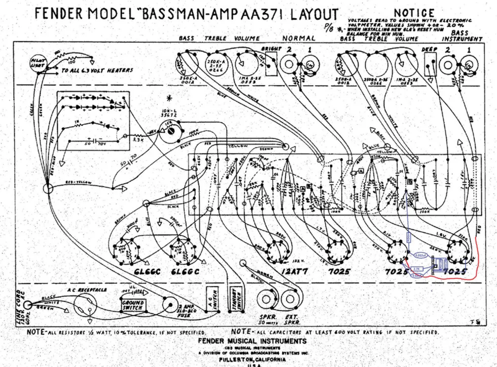
This illustration shows the gain stage mod, breaking out the area around tube positions V1 and V2 from a schematic drawing of an AA371 Bassman amp.
This mod is not very extensive, and you'll only need a few parts and a couple of pieces of wire:
- one 3-lug terminal strip (the kind typically manufactured by Keystone)
- two 470k resistors (1/2 watt is sufficient, but I typically use 1 watt for almost everything)
- one 100k resistor
- one 2.7k resistor
- one 0.022 µF 600V capacitor (poly or foil)
- one 0.68 µF 25V or greater capacitor
- two small pieces of shrink tubing or electrical tape
- one ¼" 4-40 screw and nut
- less than a foot of 20- or 22-gauge wire
Before beginning, be sure the filter caps are discharged. If you don't know how to do this, find someone who does. Then:
1. Install the terminal strip in a comfortable location between tube positions V1 and V2. You'll need to drill a small hole in the chassis and mount it using the 4-40 screw and nut. Be sure the screw and nut are very tight. This point will act as a ground connection.
2. Unsolder the wire coming from the bass channel input jacks (red, according to the schematic) that is connected to pin 2 of V1. Connect an additional piece of wire to this and insulate the connection with a piece of shrink tubing or tape. Cut to length and connect the other end to pin 2 of V2 (the input to the unused half of V2).
3. Connect one end of the 100k resistor to pin 1 of V2, but do not solder yet. Connect the other end to the eyelet where the two 100k V1 plate resistors are connected. You may need an additional piece of wire to connect to the resistor, so solder and insulate as necessary.
Warning:
All tube amplifiers contain lethal voltages. The most dangerous voltages are stored in electrolytic capacitors, even after the amp has been unplugged from the wall. Before you touch anything inside the amp chassis, it's imperative that these capacitors are discharged. If you are unsure of this procedure, consult your local amp tech.
4. Connect the 0.022 µF capacitor to pin 1 of V2. You may now solder the connection. Connect the other end of the capacitor to the top terminal strip in the drawing. Do not solder this end yet.
5. Connect one end of the 2.7k resistor and the 0.68 µF capacitor to terminal 3 of V2. Connect the other end of the resistor and capacitor to the center terminal of the terminal strip. You can now solder pin 3 of V2.
6. Connect one end of a 470k resistor to the bottom terminal and the other end to the center terminal of the terminal strip. You may now solder the center terminal.
7. Connect one end of the other 470k resistor to the bottom terminal and the other end to the top terminal. You may now solder the top terminal.
8. Connect another short wire to the bottom terminal of the terminal strip. Cut to length and connect the other end to pin 2 of V1. You may now solder both connections.
And that's it. This modification is based on the typical front end of a Marshall 2204-style head and approximates its gain control set to about 60 percent. The gain can be increased or decreased depending on the relative values of the 470k resistors. If you'd like to make the gain easily variable, you can replace the two 470k resistors with a 1 mA pot. Simply remove the 470k resistors, connect the CW terminal of the pot to the top terminal on the strip, the CCW terminal to the center ground terminal, and the wiper to the bottom terminal. This is now your front-end gain control. If you need more top end, simply connect a small value cap (start with a 100 pF ceramic cap) between the CW and wiper terminal. As with most tube amp modifications like this, feel free to experiment with slightly larger or smaller resistor or capacitor values for your own custom version.
Now break out some humbuckers and a 4x12, and rock on!
[Updated 8/17/21]