
Dear Amp Man,
Great articles. At the moment, I'm using some of your ideas rebuilding a Pignose G40V.
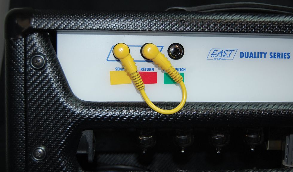
I have a Vox AC30C2X. Sounds great. It's my amp for non-in-ear gigs. It's bright and I play a Fender through it, so I've done some minor modifications to take some of the brightness out of it—nothing major. I run the amp with the two channels patched together, and one channel cleaner than the other. I never run it flat-out.
I was looking at the schematic the other day and wondering if it would be practical to run the normal channel's output from V1 through a switched jumper of some kind to the top boost's input on the other triode of V1 to cascade the channels. Would a setup like that work and get me into Mesa/Boogie, 800-pound violin territory, or would I end up with distorted mush? Foot-switchable would also be way cool. Or should I save my lunch money and get a Lone Star Special?
Any other thoughts or ideas on the Vox? Appreciate it!
Regards,
Mitch Morgan
Hi Mitch,
Thanks for reading, and glad you're getting some useful information from the column.
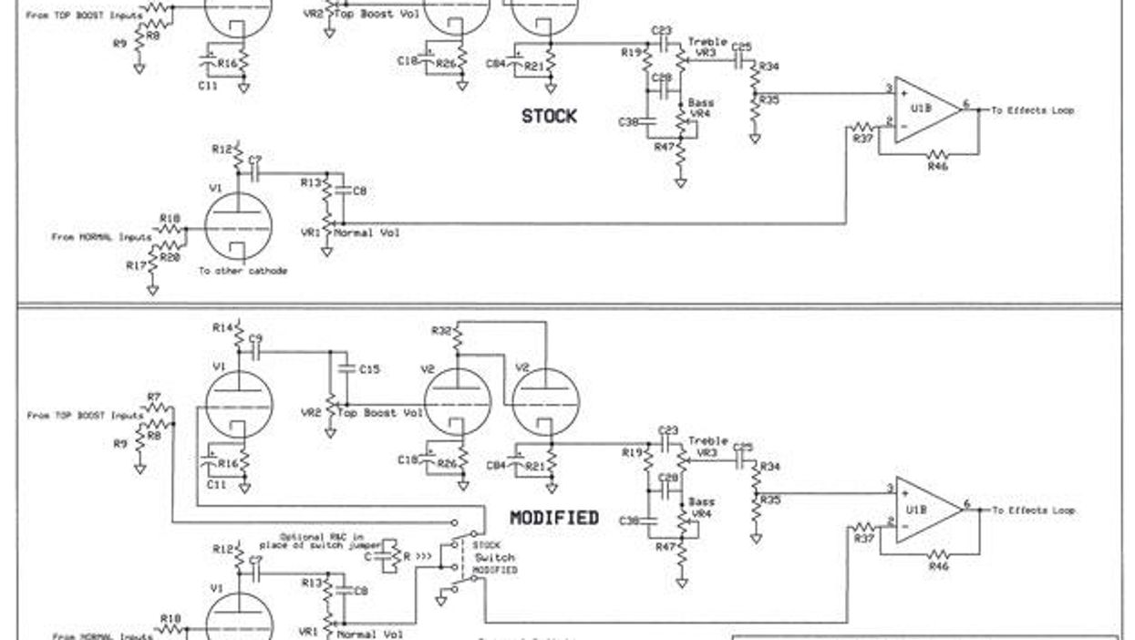
There have been so many iterations and re-issues of the Vox AC30 over the years, so thanks for being very specific as to which model you have and even supplying the schematic! There was one small issue I ran into regarding the schematic, however. The definition was not quite good enough for print, and even though I also searched the web, I could not find a better version. That being the case, I've re-drawn the necessary sections here and present them in both a “before" and “after" version, which should make it a bit easier to see exactly what's going on.
WARNING:
All tube amplifiers contain lethal voltages. The most dangerous voltages are stored in electrolytic capacitors, even after the amp has been unplugged from the wall. Before you touch anything inside the amp chassis, it's imperative that these capacitors are discharged. If you are unsure of this procedure, consult your local amp tech.The modification is not that complicated, and although this is a circuit-board amp, the procedure I propose should not require cutting circuit traces. I've also made it switchable using a DPDT on-on switch, so that one position is stock and one is modified (cascaded channels). In the “modified" position, the normal volume control will act as a pre-amp and the top boost control will act as a volume, with the master, of course, remaining a master. So let's get to it. By the way, the steps and descriptions below are also nicely mapped out on a drawing of the rear of the DPDT switch appearing on the schematic.
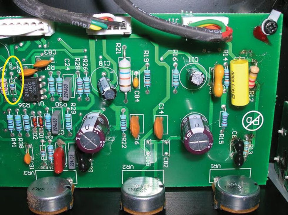
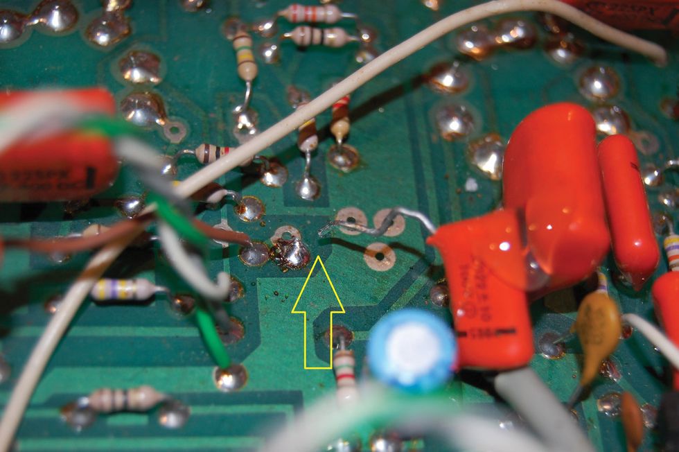
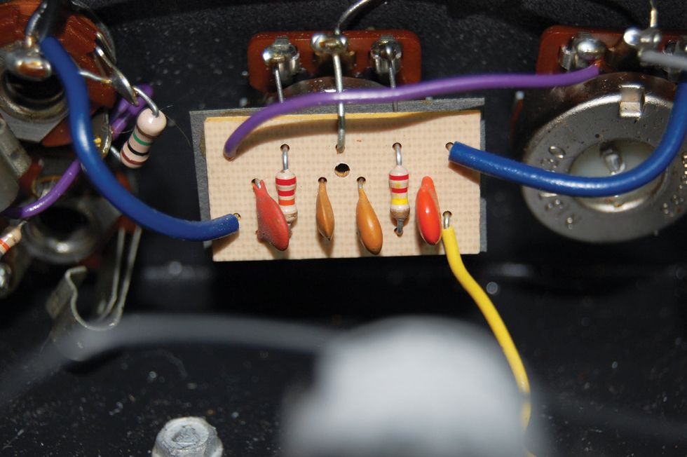
Fig. 1 — Start by lifting the side of the R37 resistor not connected to the amp's integrated circuit and attaching a new wire to it. This wire will connect to one of the common terminals of the DPDT switch.
Viva la resistors! First, locate resistor R37 (Fig 1), which connects the output of the normal channel to the op-amp that drives the effects loop, and find which side of this resistor connects to a pin on U1. Since a direct trace cannot be seen on the top of the circuit board, this can be found by using a multimeter with a continuity function. Once you find which side of the resistor is connected to the IC, lift the opposite side from the circuit board. You will then need to connect a wire to the lifted side of the resistor. This wire will run to one of the common terminals (#5) of the DPDT switch.
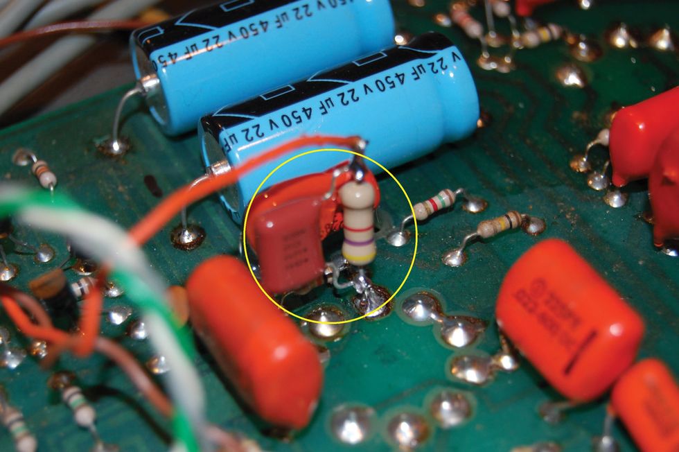
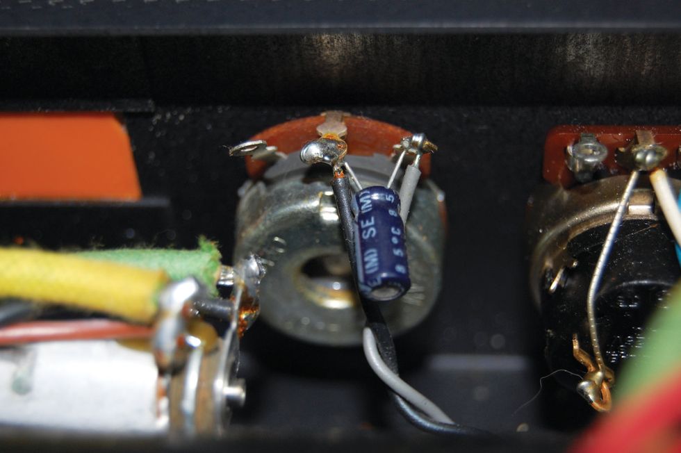
Next, locate R7 and R8 (Fig 2), which are the input resistors from the top boost jacks. Find which end of these resistors connects to the grid of V1 and lift this end of both resistors from the board. Now connect a wire to one of these pads and connect the other end to the other common terminal (#2) of the switch. Return to R7 and R8, connect the open leads to each other, and attach a wire to this junction. Connect the other end of this wire to a switch terminal on the same side as the previous wire (#1). Now connect a wire to this same position on the opposite side of the switch (#4) and connect the other end to a ground connection on the circuit board. A good spot may be the ground side of R16, which can be verified with your meter.
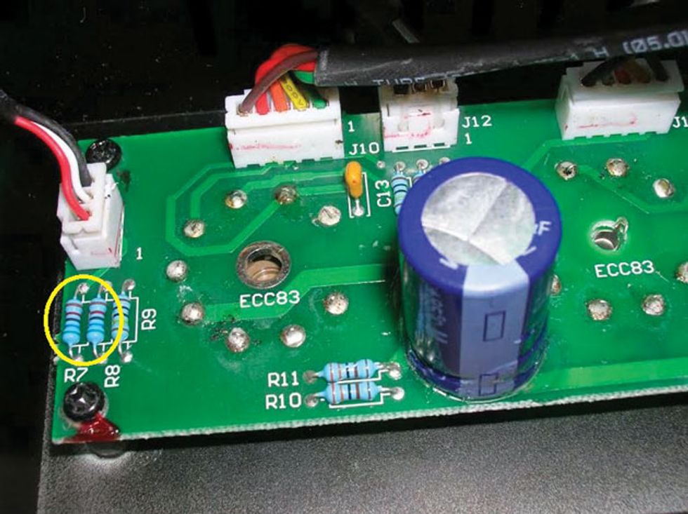
Fig. 2 — The R7 and R8 input resistors from the top boost jack must be connected to another of the switch's common terminals and brought to ground through an additional easy-but-important step.
Now, the last part of the procedure is to connect a jumper between the two remaining open terminals on the switch (#3 and #6). Also, connect a wire to one of these terminals. The opposite end of this wire needs to be connected to the wiper terminal of the normal volume control. This can be done by connecting it directly to the center terminal of V1 or to the pad where you removed a lead of R37, which may be easier to connect to.
Tune-up tips. That's it! You're all done. I'm really not sure if this will get you into 800-pound violin territory, because only a few amps are truly capable of that, but here are a few tips for this mod. First, it may be best to use coaxial cable to make these connections to reduce noise and the chance of oscillation. If you do, remember to connect only one end of the shield to ground. This will prevent any ground loops. Next, if the result here is just too aggressive, overdriven, muddy, or just plain hairy, you will need to better control the signal from the normal channel. This can be done by replacing the jumper on the switch with a resistor and capacitor in parallel. You can arbitrarily start with a 220k resistor and a 220 pf capacitor. Decreasing the resistor value will raise the signal level, and vice-versa. The capacitor controls the amount of high-frequency content in the signal. A smaller value will be brighter and a larger value will be thicker.
There you have it. Your very own Vox AC30 cascade. Enjoy!