Hello, Ask Amp Man fans. I’m once again gonna forgo a reader question and bring you a story I think you’ll find interesting. A friend recently purchased a new amp and asked me to “do the same thing you did to my other amp years ago.” That was probably 20 or more years ago, and the amp at that time was a Fender Vibrolux Reverb. What I did then was re-contour the tone of the normal channel and add reverb and tremolo to it. I’ve done this to many, many amps over the decades and I can do it in my sleep.
This time was a bit different, however, because he had purchased a new Fender Deluxe Reverb reissue. It has basically the same circuit as most Fender amps, but the reissue amps are built utilizing circuit boards. This is not a problem for me, but since the blackface Deluxe Reverb reissue—or DRRI, as they’re frequently called—seems to be very popular and are becoming ubiquitous in backlines, I thought there might be more than a few of you out there who could benefit from this modification.
A bit of warning first: The circuit boards used to build these amps are what’s known as “single-sided” boards and do not have something called “plated-through holes.” This means the thin, foil-like trace is the only thing on the board the solder adheres to. It’s a very inexpensive board, used to keep production costs down, and is not the best when it comes to servicing or modification as it easily overheats and becomes damaged. I recommend that anyone attempting to service or modify these or any other similarly constructed amps be extremely experienced with a soldering iron. Also, be aware that Fender says any mods to their new amps void the warranties.
The tone mod. Here’s the approach: First, of course, pull the chassis from the combo. Remember to disconnect the reverb and speaker cables, or else you might damage them with one big chassis pull. (I speak from experience. Ha ha!) And, by the way, if you’re so inclined, you may want to consider replacing the speaker lead with something of better quality, whether you make it yourself or buy a pre-made assembly. I’ve seen these plastic molded jacks fail more than once, and that’s not healthy for your output transformer or speakers.
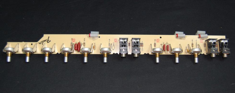
Photo 1
Next, disconnect all the ribbon connectors from the front panel board. Then you’ll need to remove all the knobs and potentiometers and jack nuts from the front panel. This will let you pull out the entire front panel circuit board assembly (Photo 1).
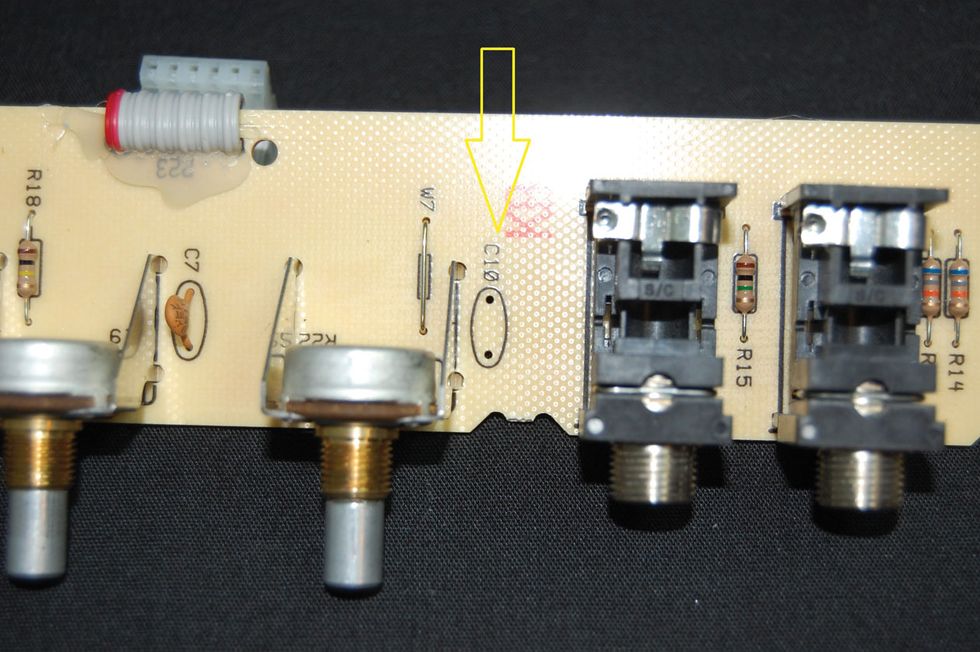
Photo 2
The first step I like to perform, since there is no bright switch on the amp, is to remove the “bright” cap (C10) from the “normal” channel (Photo 2). Next, we’ll change the bass and mid capacitors (C3 and C4) in the tone stack. The typical Fender values here are 0.1 uf and 0.047 uf, but we’re going to remove them from the board and replace them both with 0.022 uf caps (Photo 3). That will give this channel more of a mid-flavored British tone, which is a nice complement to the stock “vibrato” channel.
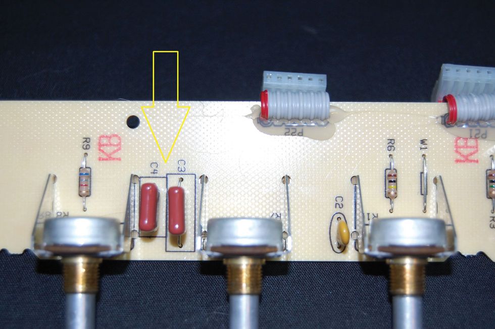
Photo 3
Reverb and tremolo. Okay, we’re finished with the tone mod on this board. So, let’s move on to the effects modification. This can be performed on the main board and in two ways. One component on this board needs to have one of its leads disconnected from the circuit board. If you’d like to do this the more “proper” way, you’ll need to unscrew all the mounting screws that attach the board to the chassis, fold it up with the dozens of other wires still attached to the board (unless you want to disconnect them all), and attempt to unsolder one lead of R12 from the board.
WARNING:
All tube amplifiers contain lethal voltages. The most dangerous voltages are stored in electrolytic capacitors, even after the amp has been unplugged from the wall. Before you touch anything inside the amp chassis, it’s imperative that these capacitors are discharged. If you are unsure of this procedure, consult your local amp tech.This would, of course, allow you to reverse this part of the mod using the original resistor, should you wish to do so in the future, but even to me, this is a bit of overkill. Instead, I would suggest simply clipping the lead on the top of the circuit board and, should you ever wish to reverse this part of the mod, worry about pulling the board and replacing the resistor at that time. It’s your call.
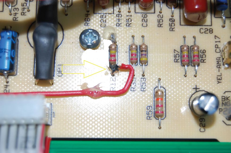
Photo 4
So, disconnect or clip the lead of R12 that points to the rear of the amp. On the other lead, which faces the front panel of the amp, carefully attach a wire (Photo 4) long enough to reach R25 with a nice routing. Attach the other end of this wire to the lead of R25 that faces the rear of the amp (Photo 5).
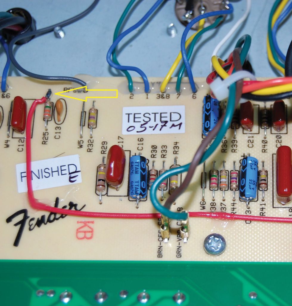
Photo 5
Jump it! To minimize failure and assure proper operation, use some silicon glue or hot wax to stabilize the cut leg of R12 and to affix the added wire to the circuit board in a few places. That’s it! Now you have a DRRI with two channels that are voiced differently, with both having reverb and tremolo. You can use an A/B box to switch between the two, or even jump the two channels together using a short cable—as we all used to do with 4-input Marshall amps! This, by the way, was not possible in the stock amp, because the two channels are out-of-phase when the amp leaves the factory and would tend to cancel each other out depending on volume settings. Funny thing about having effects on both channels: This feature is now included on the new handwired Deluxe Reverb reissues. Hmmm… Well, enjoy your new custom-wired Deluxe Reverb!