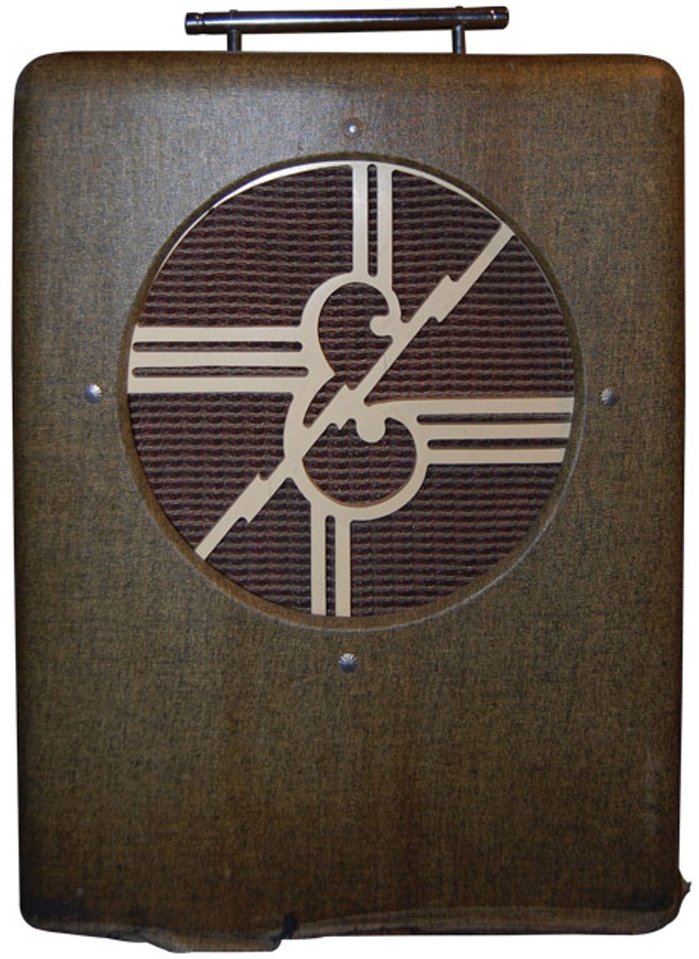

Hello Ask Amp Man readers. I know I usually answer questions from you, but I’m once again going to stray from the status quo. I had this cool old Epiphone Electar 1x12 combo, probably from the late 1940s, come across my bench and I thought it would make a great column, so here you go.
The amp came to me as “not working.” Okay—that condition could have a plethora of potential causes, but let’s troubleshoot one logical step at a time. First, I check the fuse. Yes, it’s good, but it’s a 10-amp fuse, which I’m pretty sure doesn’t belong in what is probably a 10- to 15-watt amp. Just seeing this makes me think that the mains transformer may have been forced into expiration, but let’s not assume. I’ll put in a more appropriate fuse and keep moving.
Next, I’ll pull all the tubes. Prior to doing this, one should remember to make note of the position of each tube. Sure, sometimes you can refer to a tube chart either inside the amplifier or find a schematic and tube chart online, but for this amp neither of those niceties exist, so it’s time to make a little drawing. Now, with fuse in and tubes out, the next step is to bring up the amp slowly with the help of a Variac and monitor a couple key voltages. As the voltage is increased, both the filament and the AC high voltages are coming up, so it appears that the mains transformer is still functioning. At 120V input, the AC high voltage is in the expected range and the pilot light is on, so, hey, that’s a good sign, right?
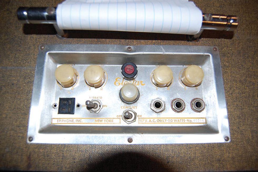
The control panel was remarkably clean for its age, but replacing the capacitor associated with the tremolo control
was a smart pre-emptive improvement.
My next step is to power down, insert a rectifier, and bring the amp up slowly again, monitoring the DC high voltage. Since this amp utilizes a tube rectifier, I’m going to substitute a plug-in solid-state module, as the tube rectifier will not show any output until it reaches operating temperature—which will not happen with low line input voltages. Bringing up the line voltage, I see the B+ voltage coming up as well. I do this slowly over the course of hours to “re-form” the caps. Once I have it up to a few hundred volts DC, I’m confident that the filter capacitors, while maybe not optimal, are at least not shorted. I also did take some resistance readings on the primary and secondary side of the output transformer, and while this didn’t tell me the full story on the transformer, it did tell me that neither side is electrically open. At this point it appears that all the major components are in working condition, so now I’ll put the tubes back in and find out why there’s no output.
I look at my tube drawing, reinstall tubes, turn the amp on, the pilot light comes on, the fuse does not blow, I plug signal into the input jack, and turn up the volume control and … the customer is correct. No output. Okay, the first question I have about this amp is “Why does it have three 6V6 tubes?” Generally, 6V6s are used for output tubes and can occasionally be found as a reverb driver. This amp has no reverb, so what’s going on?
In looking at the circuit, I determined that the socket with the third 6V6 is the phase inverter, which drives the output tubes. Funny, I’ve never seen a 6V6 used as a phase inverter. Ever! This tube just doesn’t belong here. In looking at the wiring, I can see that it’s definitely not wired for a 6V6, but is wired for an octal tube much more suitable for a phase inverter: a 6SL7. I install a 6SL7, turn the amp on, and voilà, we have a tiny bit of sound. Progress!

Fig. 1 — DC voltage leakage was one problem with this amp, but note the easy-to-access layout of the capacitors and wiring, which made replacing resistors and caps easier.
WARNING:
All tube amplifiers contain lethal voltages. The most dangerous voltages are stored in electrolytic capacitors, even after the amp has been unplugged from the wall. Before you touch anything inside the amp chassis, it’s imperative that these capacitors are discharged. If you are unsure of this procedure, consult your local amp tech.It’s time to get serious and start checking for bad components. I flip the chassis over and start measuring resistors. The first one reads more than double its value. Okay, so that one has drifted way out of range and needs to be replaced. Next one, same thing. Next one, even worse. Next one, almost open. Turns out almost every resistor, especially any that pass high voltage, has drifted so far out of spec that the circuit is barely functioning at all. I replace almost all the resistors, turn on the amp, turn up the volume, and … much better, but still weak and not good sounding. I go back in and start measuring voltages around the signal caps. Turns out that most all the signal caps have substantial DC voltage leaking through. Caps are supposed to block DC voltage and these are doing a particularly bad job. I replace all the caps showing DC leakage, turn on the amp, turn up volume and … we have an amp that’s sounding pretty respectable. At this point I’ve replaced almost all the resistors and capacitors (Fig 1), but it was necessary.
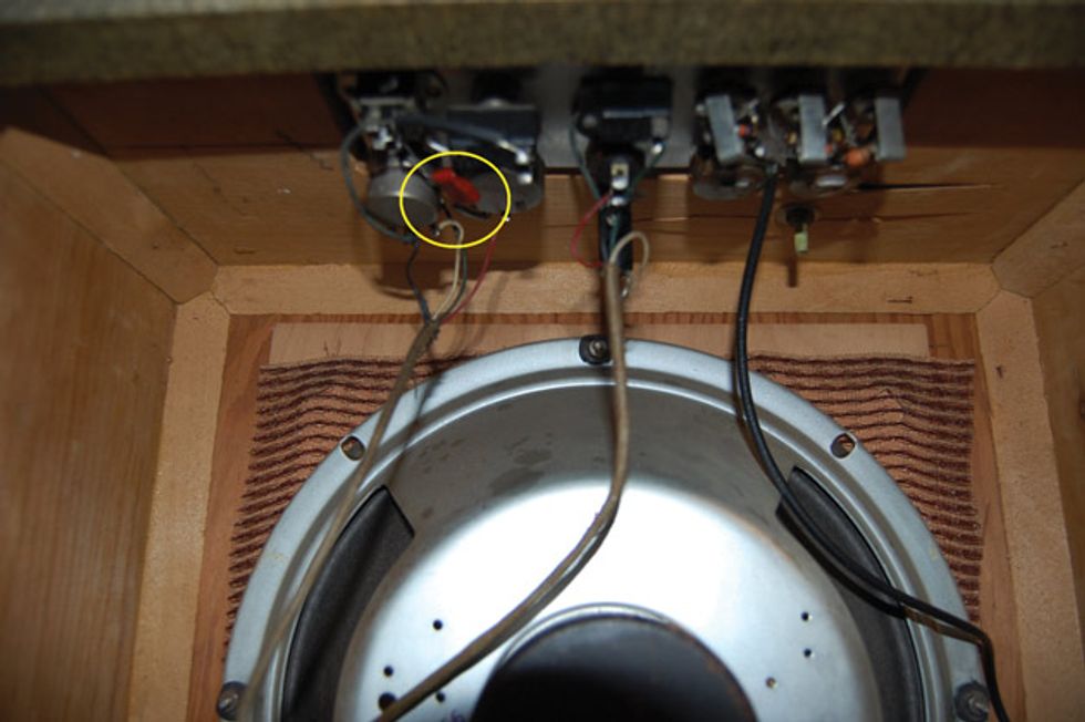
Fig. 2 — The amp’s major components were built in two parts, with the control section, in this photo, on the top and the main chassis, and with the transformer and tubes, on the bottom.
Now it’s time to check the tremolo, which, of course, is barely working. I swap out the tremolo oscillator tube, but no improvement. This amp is actually in two parts: the main chassis on the bottom of the cabinet with all the transformers, tubes, etc., and the control panel mounted to the top with the input jacks, power switch, and all controls for volume, tone, and tremolo. There is also a capacitor associated with the tremolo on this panel (Fig 2). I replace the cap and now we have a respectable tremolo. All is good … almost.
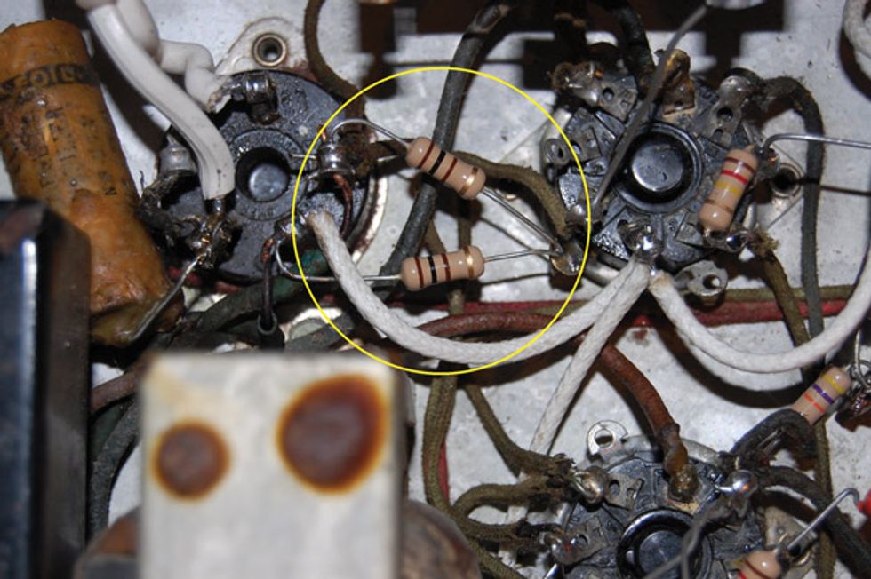
Fig. 3 — Once the amp was working again, the final touch was adding a hum balance resistor at the end of each of the filament lines and connecting them to ground.
The amp, while now functioning well, has a low-level hum. Well, I’ve gone this far and the customer tells me he wants to use it for recording, so why not try to get it a little more right? I clip some additional filter capacitors across the existing caps. If this minimizes the hum, then maybe the filter caps are not up to snuff and need to be replaced. Using alligator leads, I clip in some new filter caps across those caps, turn the amp on, turn up the volume, and … the same hum.
So okay, the filter caps are doing an adequate job on their own, as additional filtering doesn’t help. But where is this hum coming from? I realize this amp has an old-style filament wiring, found on many amps from this era including some tweed Fenders. One side of the filament winding coming from the mains transformer is tied to the chassis, with the other lead going from one tube to the next, connected to one of the tube’s filament connections. The other filament connection is connected to the chassis to complete the circuit. This wiring configuration seems to induce a low-level hum in amps. My solution: remove all filament connections to the chassis, including at the transformer, and run the second filament line to all the tubes. Once that’s done, I add a hum balance resistor at the end of each of the filament lines and connected to ground (Fig 3). I turn on the amp, plug in, and now the Electar is respectable sounding and probably quieter than when it was built. A little gem of the past resurrected.