Hi Jeff,
The first decent amp I owned was a Silvertone
Twin-Twelve 1484 I bought from my guitar teacher
in 1967 for $100. At some point I traded it, but
I’ve missed it. Now I’m in my second childhood,
so I just got one that appears to have been made in
1965. It has all the original components and needs
a cap job and general maintenance. The reverb and
tremolo work fairly well, but could be stronger. Do
you have any suggestions for making this amp all it
can be? I just want the amp to be as robust as I can
make it, so I can crank it up and enjoy the sound.
I know the 1965 Jensens won’t take a lot of abuse,
so I would play through another cabinet with relatively
new speakers when cranking it up.
 Are there any different values you’d suggest
for the 100 μF 150 VDC filter caps or any of
the other components? In addition to the filter
caps, there is a 5-10-20 μF 450 VDC can cap.
I can’t find a source anywhere that has those
values. Do you know of one? Or if not, what
available can cap would you suggest? Also, are
there any mods you’d suggest?
Are there any different values you’d suggest
for the 100 μF 150 VDC filter caps or any of
the other components? In addition to the filter
caps, there is a 5-10-20 μF 450 VDC can cap.
I can’t find a source anywhere that has those
values. Do you know of one? Or if not, what
available can cap would you suggest? Also, are
there any mods you’d suggest?
I’ve been working on amps for about three
years now, and I’m at the point where I can
do basic amp troubleshooting, cap jobs, etc. If
I’m not comfortable attempting anything you
suggest, I’ll take it to an experienced amp tech.
Thanks!
—Dave Ellis
Hi Dave,
Thanks for writing. I actually
owned a 1484 head years ago
and wish I still had it. Just the
fact that you could turn the
volume control off and turn the
reverb control up to get nothing
but cavernous, sci-fi reverb
made it cooler than most other
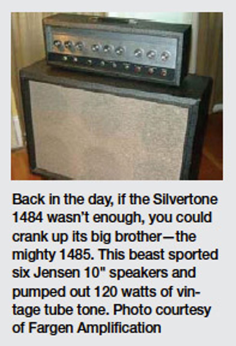
amps. Another cool fact: The
1484 is almost identical to the
higher-powered 1485 favored
by Jack White. The 1485 has
four 6L6 output tubes, double
the power, and four more speakers!
Yes, the 1485 had six 10"
speakers. But hey, those two
vintage 12" Jensens in your
amp are pretty sweet, too.
You mentioned the amp
needs a cap job. In 1484s, the
filter capacitors in the initial
section of the power supply
are crucial. This power supply
employs a very nontraditional
voltage-doubler type of circuit.
In fact, it employs two voltage-doubler
circuits running off
two separate secondary taps of
the mains transformer. These
circuits are placed in series and
the voltages add to develop
the 480 VDC plate voltage
stated on the schematic. If these
capacitors are dried out and
underperforming, the proper
voltages will not develop,
resulting in low plate voltage
and low output. Replacing the
four 100 μF 150V caps in the
voltage-doubler circuit generally
improves performance.
If you can source a slightly
higher capacitance or higher
voltage, feel free to do so.
While the original capacitors
are mounted in an area that
initially may have been a tight
squeeze, newer capacitors are
physically smaller so you might
be able to install higher-value
capacitors in the same space.
Substantially larger capacitance
values, however, may adversely
affect the amp’s tone and
response, so don’t go overboard.
Regarding the 5-10-20
“Twist Lock” can cap in the
power supply: Sorry, I don’t
know where to find any.
Through an extensive search,
you may find a New Old Stock
(NOS) version somewhere, but
I’d strongly recommend properly
re-forming the cap. Even
then, its performance may be
suspect. Instead, I’d recommend
installing discrete 5, 10, and
20 μF 450V caps. (If you can’t
find a 5 μF 450V cap, an 8 μF
would work fine.)
Remove the wires from each
terminal of the can cap and
connect them to the positive
side of the appropriate replacement
caps. Don’t forget to
connect any applicable resistors
between the appropriate capacitors.
Connect all the negative
leads to ground (it’s generally
best to keep ground connections
as close to the original
capacitor as possible, but space
doesn’t always allow for this). If
there’s room to install a terminal
strip for all these cap connections,
that would be great,
but I doubt there will be. Just
remember to do neat work,
keep leads as short as possible,
insulate as necessary, and find
a way to anchor the caps to
something rigid via wire ties,
silicone glue, or some other
appropriate method. Also, while
you’re there, you should replace
the 100 μF 50V cap in the bias
supply. If this cap is bad or
weak, it will cause additional
hum in the output stage.
The 1484’s output transformer
is a bit small, so I’d be careful
not to run the amp at high
volumes for extended periods.
That said, there is a simple mod
that will give you more gain, as
well as two different-sounding
channels. R22 and R23 on the
schematic are the cathode resistors
for the second 12AX7 in the
circuit. Parallel a 0.47 capacitor
across R22 and a 2.2 μF
capacitor across R23 (watch the
polarity—positive side toward
the tube). This will increase gain
in both channels, with channel
1 being brighter and channel 2
being more full bodied.
Here’s another quick mod.
The 1484’s standby switch is
different than most: It does not
disable the high voltage—it simply
cancels the signal going to
the output tubes. Try removing
the switch and replacing it with
a 1 Meg linear pot. Connect the
two wires that were attached to
the switch to the pot, one on
the wiper and one on the CCW
leg. Turning the pot all the way
down will yield the same result
as the original standby switch,
while turning it up will control
the amount of signal going to
the output tubes.
Hopefully, the capacitor mod
will give you more gain in the
front end so you don’t have to
push the output stage so hard.
That said, there’s nothing like
the sound of output tubes distorting,
so if you need to crank
it, go ahead. Luckily Mercury
Magnetics makes replacement
transformers for these amps, too.
There you go. I’ll bet Jack
White doesn’t have these mods!
 Jeff Bober is one of
the godfathers of the
low-wattage amp revolution,
co-founded and was
the principal designer for
Budda Amplification. Jeff recently launched EAST
Amplification, and he can be reached at
pgampman@gmail.com.
Jeff Bober is one of
the godfathers of the
low-wattage amp revolution,
co-founded and was
the principal designer for
Budda Amplification. Jeff recently launched EAST
Amplification, and he can be reached at
pgampman@gmail.com.
![Rig Rundown: The Black Crowes’ Rich Robinson [2026]](https://www.premierguitar.com/media-library/youtube.jpg?id=66952027&width=1245&height=700&quality=70&coordinates=0%2C0%2C0%2C0)