
Hello Ask Amp Man followers. Greetings from Amp World!
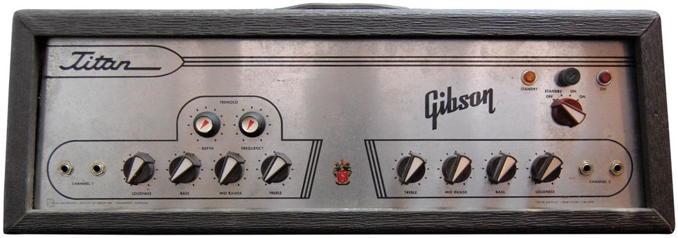
An amp crossed my path that I think is interesting enough to warrant an installment of the column, so I’m once again going to forgo a reader question and focus on this somewhat rare brown box on my bench called a Gibson Titan. A friend who recently acquired the head and cabinet pair brought them to me. He said that he’d wanted a Titan set since seeing the trapezoidal head sitting atop its matching extension cabinet in a music store back in 1965, so this was a very welcome blast from his past.
First, a little history on these amps and then we’ll get into the servicing. According to the information I’ve found, Gibson manufactured Titans for five years. In the first two years, 1963 and 1964, they were produced with a brown vinyl covering, and in the last three years, 1965 through 1967, they were covered in black vinyl. Titans were also offered with multiple speaker configurations. The cabinet in the Titan I set came loaded with two 12” speakers. The Titan III had one 15” and two 10” speakers, and the Titan V had two 15” speakers.
All of these configurations used the same head containing 11 tubes, utilizing a quad of 6L6 output tubes, and it was rated at 65-watts output. The cabinet associated with this head says Titan III on its decorative metal panel, so it’s the one 15” and two 10” version. The interesting thing about this configuration is Gibson installed a crossover in the cabinet so the lows and highs would be split between the 15” and 10” speakers, respectively. That’s not something seen often in guitar world. As for the head and cab, they’re covered in the earlier brown vinyl and the date codes on the parts are split between late 1963 and early 1964, so that should firmly date this Titan as a 1964 model. Nice find indeed!
The owner said this amp was sitting for a while and he wanted it serviced and brought back to its glorious self. He also mentioned that one of the output tubes was either missing or looked bad, so he installed a new quad of output tubes and turned it on, but it didn’t sound right and was making noises. As some of you may know from reading my columns through the years, that was a bad thing to do, but it was also good information for me to have.
WARNING:
All tube amplifiers contain lethal voltages. The most dangerous voltages are stored in electrolytic capacitors, even after the amp has been unplugged from the wall. Before you touch anything inside the amp chassis, it’s imperative that these capacitors are discharged. If you are unsure of this procedure, consult your local amp tech.I, as well as many others in the tube-amp service industry, have always said, “If an amp has been sitting idle for years, it’s not a good idea to just plug it in and turn it on.” The electrolytic capacitors in the amp tend to dry out, and if there’s any hope or desire of keeping the amp original, as well as in service, the caps should be brought up slowly over time with a Variac to allow them to “reform.” Not doing this can compromise the performance of the caps or possibly leave you with a mess that’s a chore to clean up after one decides to vent or explode. Luckily neither of these things occurred, but I made the decision that the original caps should be replaced for this Titan to become a usable, reliable amp.
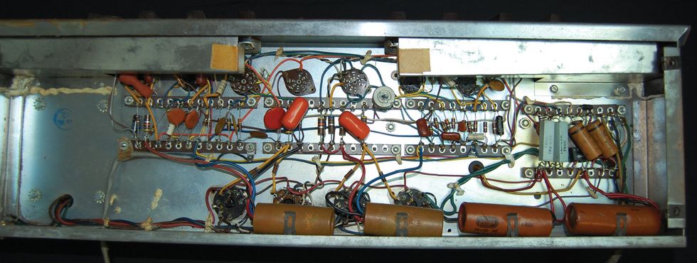
Photo 2 — The amp arrived in original condition except for the prior replacement of one output tube socket.
Let’s get into the servicing. As you can see in Photo 2, the amp is pretty darn original. The only real change to this point had been the replacement of one output tube socket. Things looked good for the most part, except for a couple small problems. The screen grid resistor on one of the output tube sockets had been fried to a crisp and needed to be replaced. This is obviously where the missing or bad output tube was located, but no worries. The amp was originally built using 1/2-watt screen resistors, but, since we had to replace one, I upgraded them all to much more reliable 5-watt versions. There was also one signal capacitor in the phase inverter section that had broken away from its connection on one side (Photo 3). Luckily there was enough lead remaining on the capacitor that I could attach an extension, properly re-attach it to the connection, and keep the part original.
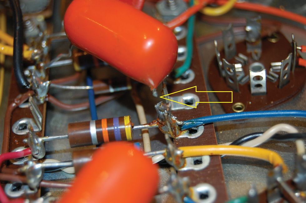
Photo 3 — A signal capacitor in the phase inverter section had broken away from its connection on one side. There was enough lead remaining to attach an extension.
So, I repaired the signal cap and upgraded the screen grid resistors. Then it was on to the filter caps, and I’d like to impart one very important piece of information here that has come from decades of experience. A fact I’ve learned that may be one of the most important to consider not only in building amps but also in repairing them is that “ground” is not just ground.
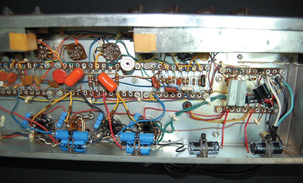
Photo 4 — When installing new caps, be sure to use the same negative connection used with the original caps, even if replacing them with a different style cap.
What do I mean by this? Connecting a component that needs a ground connection to just any location on the chassis or to any electrical connection to ground does not mean the unit will function optimally. In many instances, this will cause a low-level hum that should not exist. Proper ground location is crucial for the best performance, and in most amplifiers, that has been optimized during the design and development process. For this reason, whenever I replace filter capacitors, I make sure to use the same negative connection used with the original caps, even if I’m replacing them with a different style cap, as I did for this install. I chose to use the original wires from the multi-caps and attach them to the replacement discrete caps, which I mounted in the same locations (Photo 4).
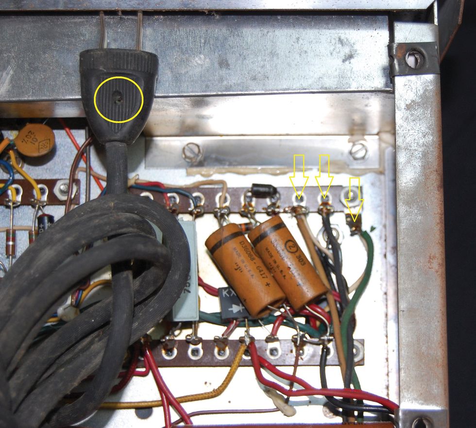
Photo 5 — The amp’s original two-prong power cord had a hole for a ground wire that was manually attached to a wall outlet’s center screw for grounding.
There you have it. A little piece of someone’s childhood music store experience is back up and running, hopefully to produce more memories. Until next time…