
When I was learning about amps and wondering how a tube actually amplifies a guitar’s signal, I was a little stumped. It took many nights of reading my new favorite books, Dan Torres’ Inside Tube Amps: The Book on Tube Amps Technology and Gerald Weber’s A Desktop Reference of Hip Vintage Guitar Amps, over and over to set the mental stage. The key for me was grasping the concept of bias. Essentially, we set the bias of an amp to a setting that is just right for the flow of current when that amp is idling—that is, turned on and ready to rock. How do we figure out what that setting is? Read on, and remember that the guitar signal coming out of our pickups is AC. It is modulating up and down—plus and minus—in reaction to our strings moving back and forth over the pickups. And please remember we are generalizing.
For a preamp tube to amplify effectively, it needs to be in its happy place: not too hot, not too cold—the electron porridge flowing through the tube must be around the midpoint of the tube’s safe current capacity. So, if a tube is safe running from 0 milliamps to 10 milliamps, then we want to set it at 5 mA. From this midpoint, the tube can conduct more or less current in response to our guitar signal. The British call tubes valves, and it makes a lot of sense when thinking about bias. Consider a garden hose. When the spigot is closed, no water flows. When you fully open the spigot, there is maximum flow. When you just open the spigot or valve enough so half the water flows, you can now mimic the less-and-more signal flow of the guitar by twisting the spigot back and forth. Similarly, electrical guitar signals increase and decrease tubes’ current flow. The key is that small changes at the tube input create bigger flow changes at the tube output, aka gain!
For us to take the next step forward, we need to look back to 1827. Did Georg Ohm know he was helping plug Malcolm’s SG into something loud and wonderful? I like to think he did. Look at his eyes in a portrait—they’re wicked! Ohms Law is voltage = current x resistance (V = IR). So, with basic math we can see how bias comes to be.
A preamp tube like a 12AX7 has three parts: the grid, where the guitar signal goes in; the plate, where the guitar signal/electrons come out; and the cathode, which connects the tube to ground, where the electrons live. The electrons flow from ground up to the cathode and onto the plate and back to the filter caps/power supply. If a preamp tube was not biased (set to middle range electron flow), it would draw as much current as possible and probably burn out.
A typical 12AX7 likes about 1 mA of idle current as its middle ready-to-work happy spot. Different tube types have different current capacities, all the way up to large power tubes that are fine with 100 times more current then a preamp tube. The electrons are negatively charged, and the plate has a large positive voltage that attracts those electrons in the worst way! They want to get there bad. But for the tube to be a good valve, we need to put the brakes on and let only some of those eager electrons through. It turns out that if the grid is negative with respect to the cathode, some of the negatively charged electrons will be repelled by the grid and will be shielded from the attractive force of the positive plate. Essentially, opposites attract and like charges repel.
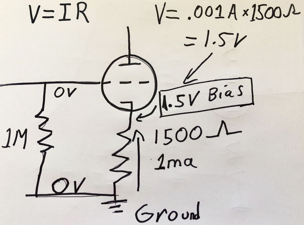
Got that? Okay. Now, take a look at the drawing (Fig. 1). If 1 mA flows through the 1.5k cathode resistor, this will create a voltage over the resistor following Ohms Law. So, as we see at the top of the drawing and in its diagram, .001 amps x 1500 ohms = 1.5 volts. So a typical 12AX7 likes a bias of 1.5 volts.
But wait. We want the grid to be negative with respect to the cathode, which is at +1.5V. To get this relationship, we need another part: the grid leak resistor. This large resistor is there so the grid has a reference to ground, where the cathode is also connected. There is no current flow through the grid leak resistor, so there is no voltage change, so the grid stays at 0 volts—just like the ground point. And the cathode enjoys its +1.5V. Eureka! Now the grid is at 0 V and the cathode at +1.5V, so the grid is 1.5V less (negative) with respect to the cathode. To the tube, this is the same as the cathode at 0 and the grid at -1.5V. We have achieved our bias! All tube types are different, but for your average 12AX7, a bias of 1.5V yields a 1 mA current flow (in general—please). If you are into this stuff, get those books and make some amps!


![Rig Rundown: Russian Circles’ Mike Sullivan [2025]](https://www.premierguitar.com/media-library/youtube.jpg?id=62303631&width=1245&height=700&quality=70&coordinates=0%2C0%2C0%2C0)