For a certain breed, the very notion of pedal
modifications—the process of changing
or altering some aspect of an existing effects
pedal—conjures dreams of creating the ultimate
pedal. Something uniquely capable of
providing a portal into uncharted regions of
creativity. Something that inspires gig tales
in the vein of, “Yeah, man, I was about to
launch into my solo, so I stepped on my
custom-modded [INSERT PEDAL NAME
HERE] and … Oh. My. GOD. The heavens
opened … angels wept … and some guy
with excellent hair and a beard gave me the
Arthur Fonzarelli double thumbs up. My solo
changed lives that night. Some say world peace
became a tangible possibility. However, it
would have been nothing without my custom
modded [INSERT PEDAL NAME HERE].”
Or something like that.
At the other end of the spectrum, you’ve
got players who ask, “Why on earth would
I want to mess with a perfectly good piece
of kit?” Which is a fair point, to be sure.
And then there are those in the middle who
are curious and who, maybe—just maybe—
might like to try a few easy or medium-difficulty
mods just for kicks. This article is
for those guys.
Though all mods are intended to result in
elevated creative output, they fall into three
categories: aesthetic, tonal, and structural.
Aesthetic mods alter or improve the stompbox’s
appearance, tonal mods change the actual
sound of the device, and structural mods
improve the pedal’s build quality or reliability.
If you’re ready to take on one or more
of the following mods, please read all the
instructions before deciding if you want to
try it, and only do so if you’re confident
you can complete the procedure. All the
mods work perfectly when executed correctly,
but neither Premier Guitar nor I can
provide support if things don’t work out
right. (Sorry!) Another point to keep in
mind before proceeding is that your pedal’s
warranty will be rendered null and void as
soon as any aspect of its circuit is modified.
If you’re cool with that, let’s dive in.
Soldering Brush up
Okay, first things first. These mods require
you to open up your pedal and desolder
and solder things. If you’ve never soldered
before, you’ll definitely want to practice a
bunch before dripping molten metal alloys
into your beloved pedal. You can find a very
helpful and thorough soldering tutorial on
YouTube. We've embedded below “How and Why
to Solder Correctly" and “How to Solder:
Removing Solder.”
All right, now that that’s all sorted, on to
the fun stuff!
MOD 1: LED REPLACEMENT
Mod Type: Aesthetic
Difficulty Level: Easy
What You Need:
• Soldering iron
• Solder
• LEDs (same size
as existing LEDs)
• Replacement clear
bezels (optional)
• Side cutters
• Solder sucker
• Phillips screwdriver
Our first mod is replacing a stompbox’s
LEDs. It’s purely for visual vibe, but it’s
a fun way to make your pedal a little more
unique—and to get your feet wet with some
pedal-modding basics.
A light-emitting diode (LED) is a small
diode that emits light when a direct current
is passed through it. Like all diodes, LEDs
have polarity, like batteries, and therefore
need to be hooked up properly on their
positive and negative sides in order to work.
When I was looking for a pedal that
could use some tarting up, I came across a
Danelectro Reel Echo. Perfectly cool pedal,
but its red LEDs don’t fill me with the requisite
visual joy one would like when engaging
the sonic glory of a delay. The Reel
Echo is particularly good for a first-time
LED-mod experience, because it’s large and
the LED board is easy to get to.
To remove the old LEDs and install
the new ones:
1. Open up the beast. This particular
device requires removing four screws
and sliding the bottom chassis out.
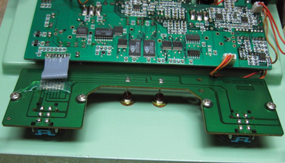
2. Remove the four screws that secure
the switch/LED board, then turn it
around to reveal the two red LEDs.
3. Use a ruler or calipers to measure
them so you can purchase replacements
of the proper size.
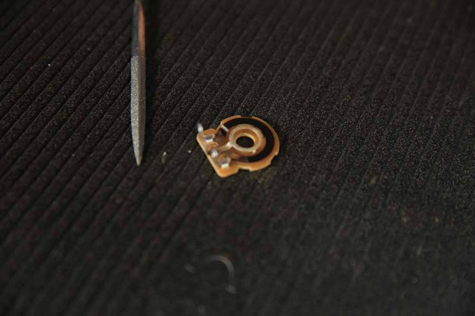
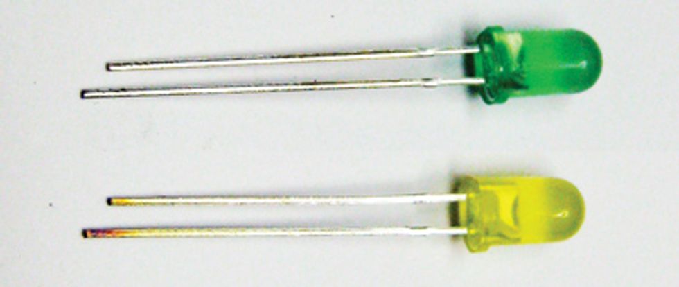
4. Once you’ve purchased replacement
LEDs and are ready to proceed with
installation, take a close look at them.
See how the two legs go up into the
plastic, and one connects to a larger
tag of metal while the other connects to
a small tag? The larger tag is always the
cathode—or negative—side, while the
little tag is the anode—or positive—side.
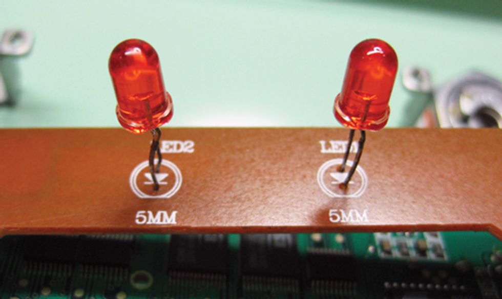
This unit couldn’t be more perfect
for this mod, because the board
features the diode schematic symbol,
which shows you which way the LEDs
should be inserted. The cathode side
goes in the hole near the base of the
diode schematic symbol’s triangle. The
anode goes in the hole near the line at
the tip of the triangle.
5. Desolder and remove the two old LEDs.
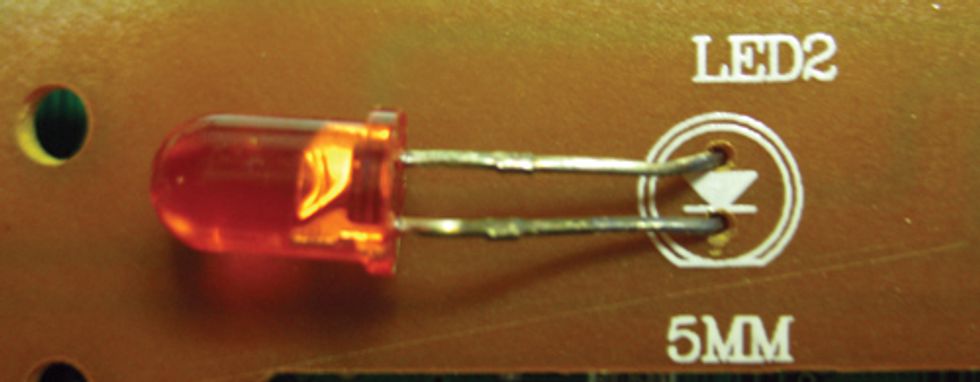
6. Insert and solder your new LEDs—being
super careful to get the polarity correct.
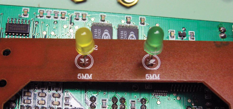
7. Splendid—you’re done! (Note that,
because the Reel Echo comes with
red bezels—colored lens-type covers
over the LEDs—I replaced them with
transparent bezels that reveal the yellow
and green LEDs. Your pedal may or
may not require new bezels in order
to show your new LEDs.)
MOD 2: 1/4" INPUT AND OUTPUT JACK REPLACEMENT
Mod Type: Structural
Difficulty Level: Easy
What You Need:
• Soldering iron
• Solder
• 1/4" mono Switchcraft jack
• 1/4" stereo Switchcraft jack
• Wire strippers
• Side cutters
• Nut socket for jack
socket nut
Our guinea pig for mods 2, 3, and 4
is a charming little Vox V847 wah.
This will do rather nicely, because its
construction allows us to modify various
bits without having to mess around much
with circuit boards. For our second mod,
we’re going to replace the stock 1/4" jacks
with top-shelf Switchcraft sockets that
will improve reliability. This isn’t to say
that the original jacks aren’t any good, it’s
just that the Switchcraft sockets are a little
more rugged and durable.
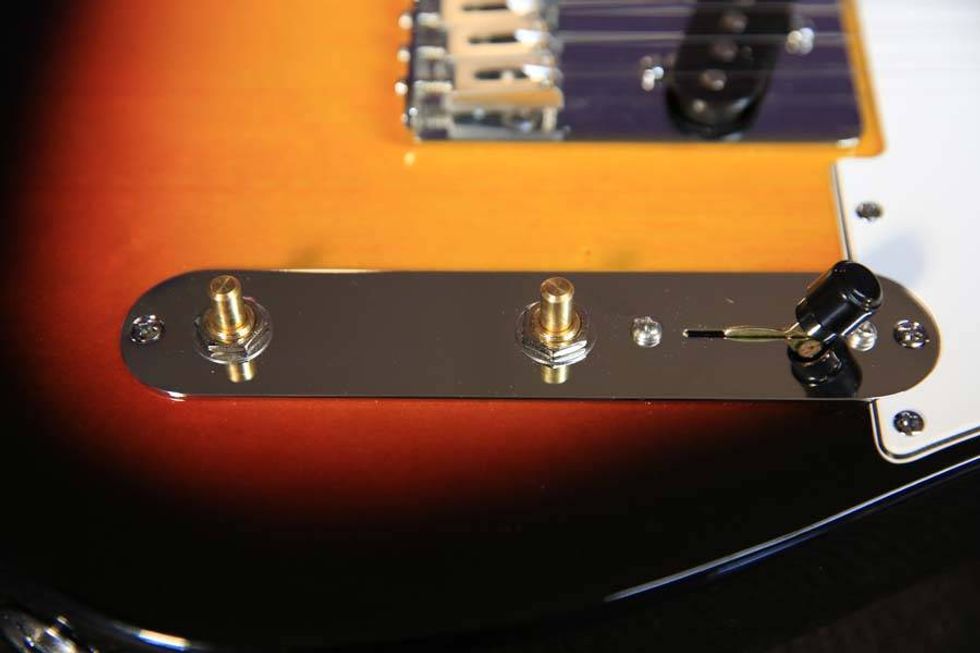
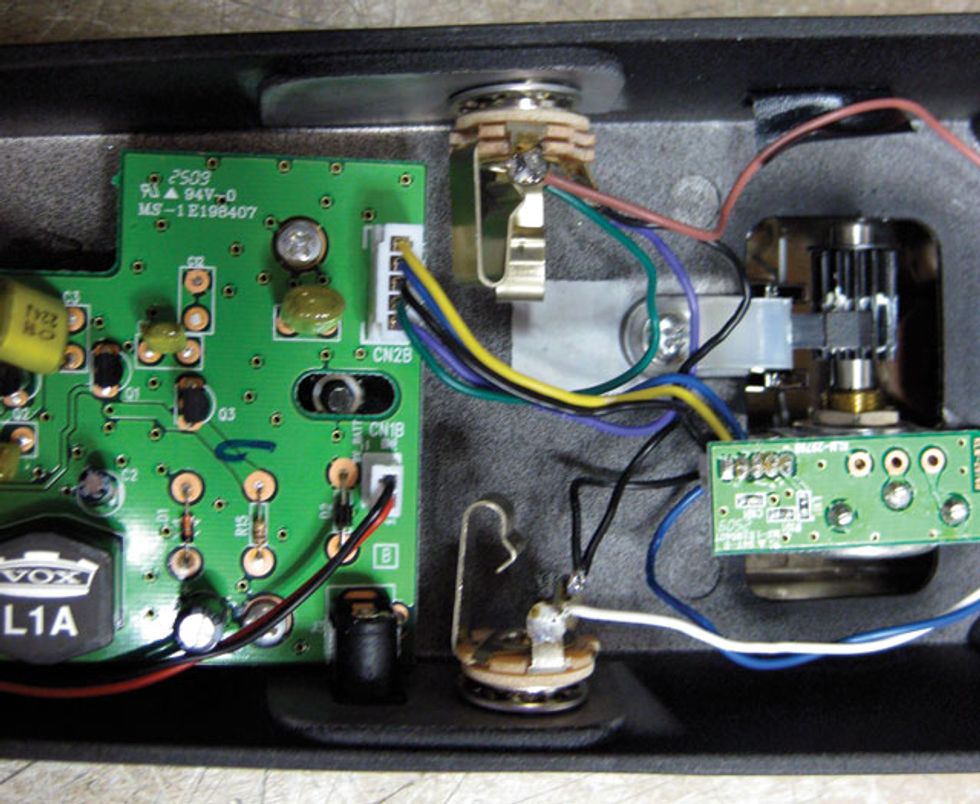
Let’s have a look inside. See those two
rectangular black boxes just above the
main circuit board? Those are the jacks—
the input is on the left, and the output is
on the right.

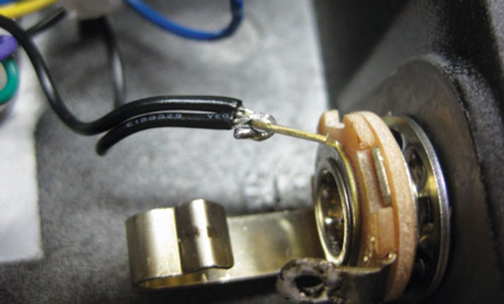
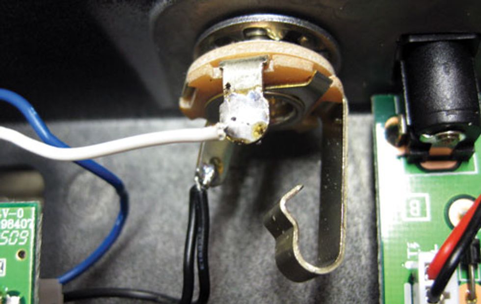
Now let’s take a closer look at the wiring
of the output socket (which, again, is on
the right side when the pedal is turned over).
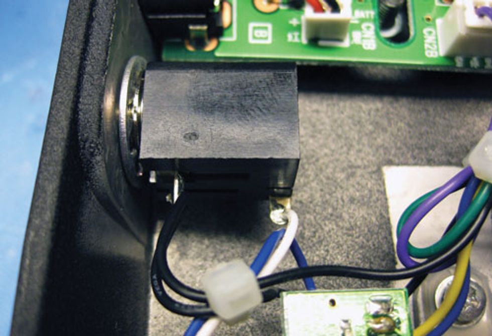
Notice that the white wire attaches to
the “tip” tag of the jack, and the black
wires connect to the “sleeve” tag.
To remove the old output jack:
1. Heat up your soldering iron.
2. Desolder all three wires.
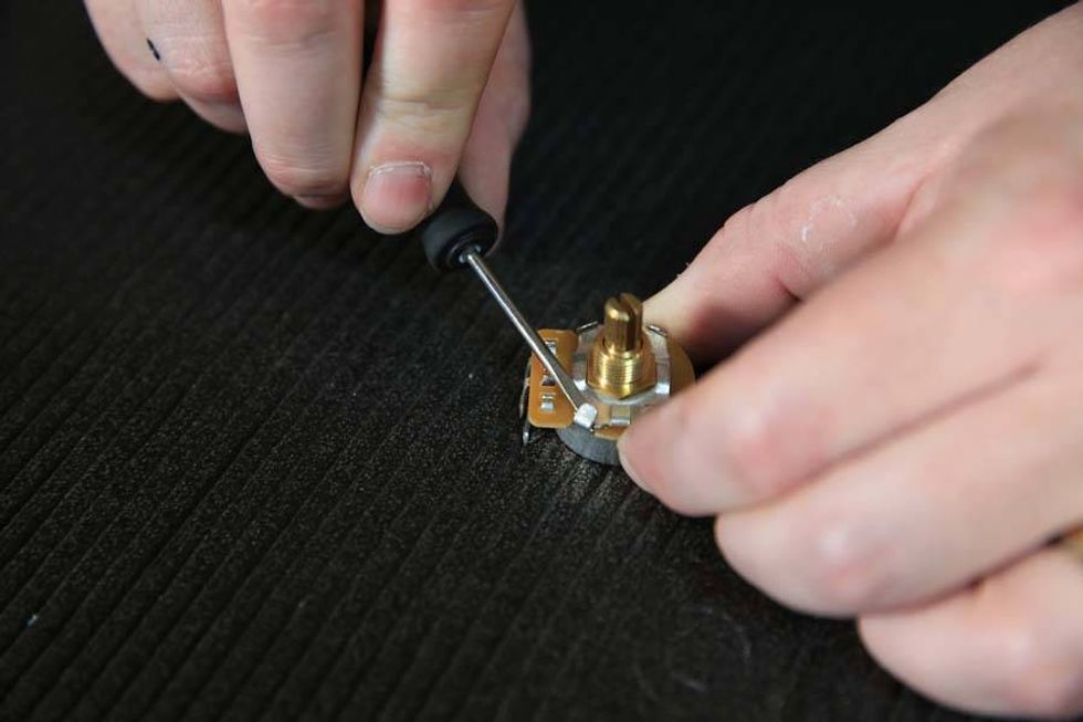
3. Unscrew the nut that holds the
socket in place.
4. Remove the old jack.
To install the new output jack:
1. Take one mono Switchcraft socket and insert into the empty hole.
You may need to use an awl or
drill to slightly widen the hole so
that the new jack fits.
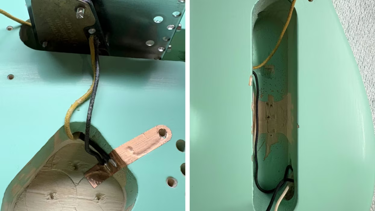
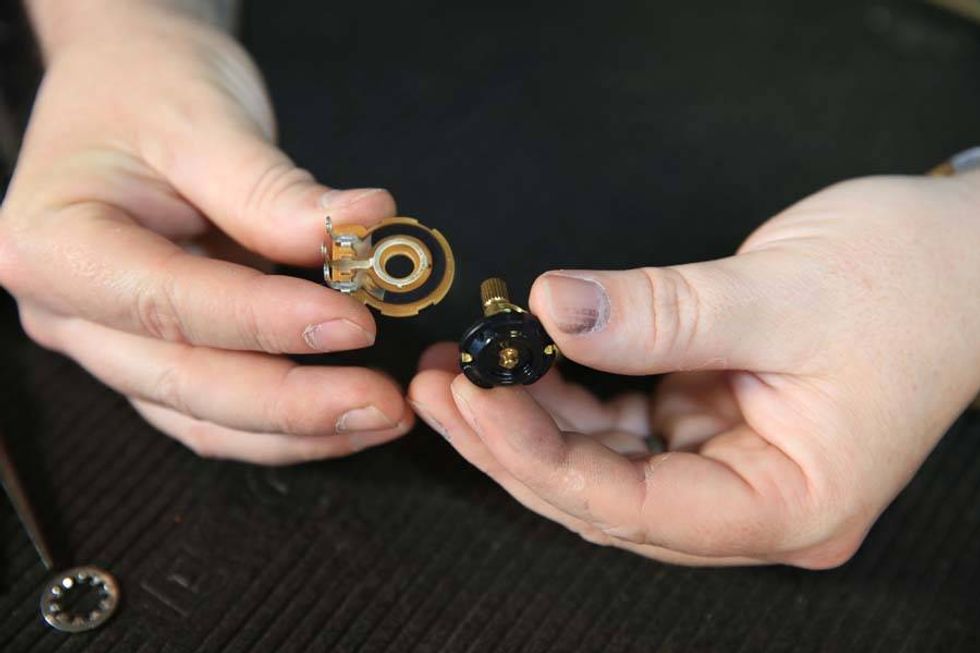
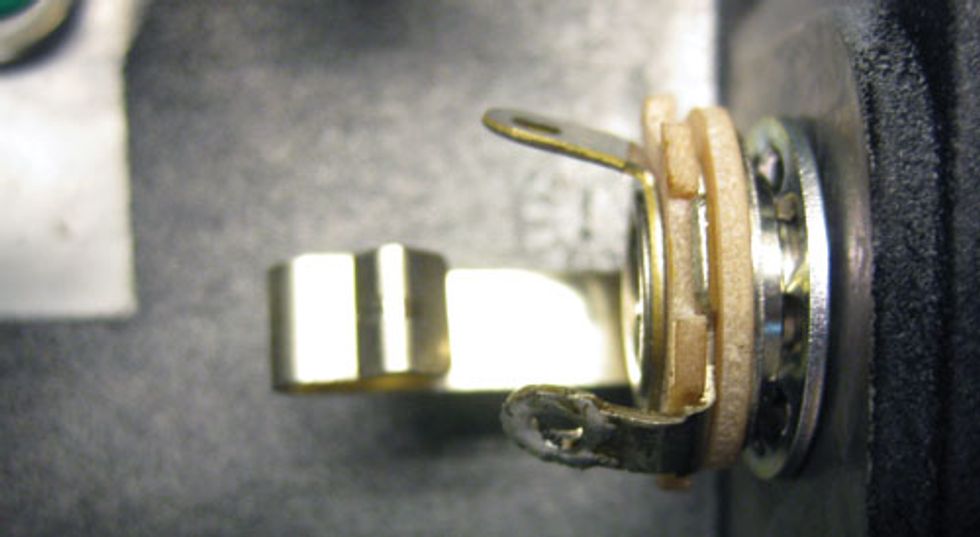
2. Screw the nut in place. Be sure to
include the locking washer
between the socket and the side of
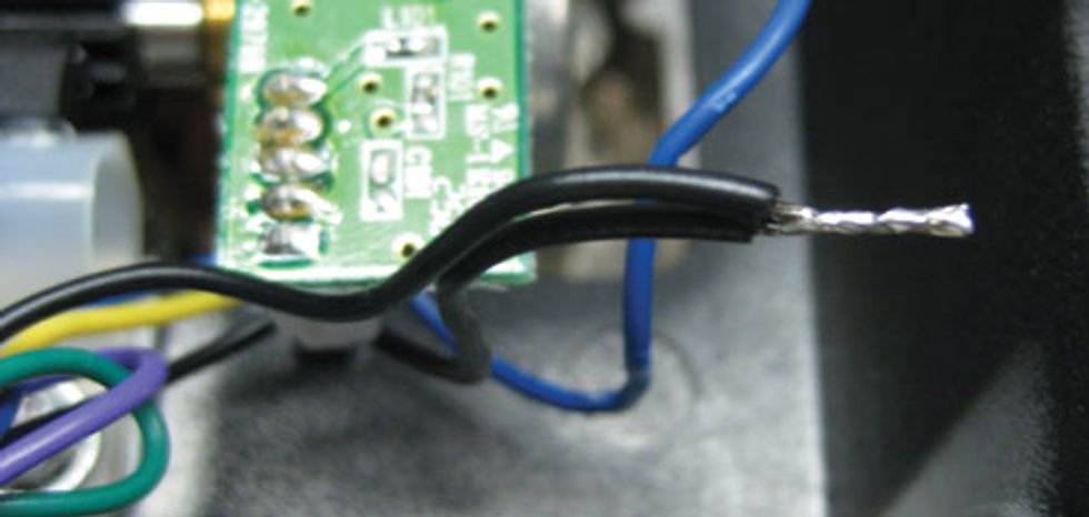
the wah (as shown below).
3. Mad wicked—well done. Now
take the black wires that were
attached to the ring tag of the old
socket and strip a little more than
half an inch of plastic off the ends.
4. Twist the exposed parts of both black
wires together (as shown below).
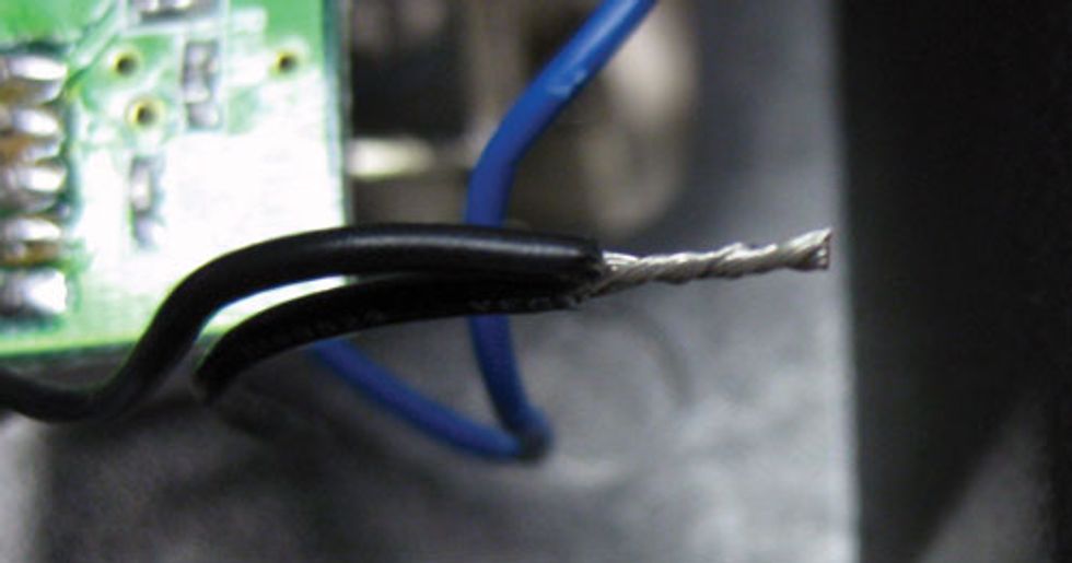
5. Now “tin” the twisted wires (as shown
below). For help on this, refer to the
previously mentioned YouTube solder
primers. (Note: You’ll need to tin every
wire you solder in these projects.)
6. Bend the tinned wires into a hooked
shape like the one shown below.
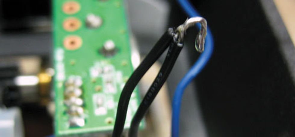
7. Thread the hooked black wires
through the sleeve tag of the new jack
(see below).
8. Solder the two black wires to the
sleeve tag.
9. Thread the white wire through the
new jack’s tip tag (the only socket
tag remaining).
10. Ace. Your new jack should look
a lot like this.
Now let’s move on to the input socket,
which has an additional wire—the battery-switch
wire. If you’ve ever wondered how
your pedal’s battery is turned on when you
plug in, this little wire is the key. When the
1/4" cable is inserted, it shorts a connection
between the sleeve tag and the ring tag of
the socket. The sleeve tag is connected to
the circuit’s ground terminal. The green wire
connects to the negative terminal of your
battery. A circuit is made once the negative
terminal of the battery is connected with the
ground (or negative) terminal of the circuit.
Voilà—it’s alive! Very clever, eh?
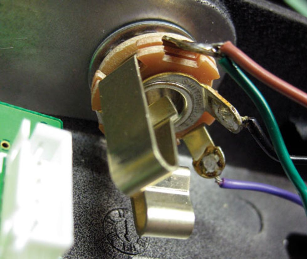
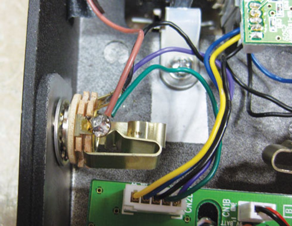
Have a look at the next photo—it’s the
original input jack.
The black wire is the ground wire, which
goes to the sleeve tag of the new Switchcraft
socket. The green and brown wires carry
the audio signal and are connected to the
tip tag of the new jack. The purple wire is
the battery switch that connects to the ring
tag of the socket.
To remove the old input jack and install
the new input jack:
1. Remove the wires in the same manner
you did with the output jack.
2. Strip and tin each wire.
3. Unscrew and remove the old
input socket.
4. Solder the brown and green wires
to the tip tag.
5. Locate the sleeve tag—which attaches
to the center portion of the socket—
and solder the black wire to it.
6. Solder the purple wire to the
remaining tag.
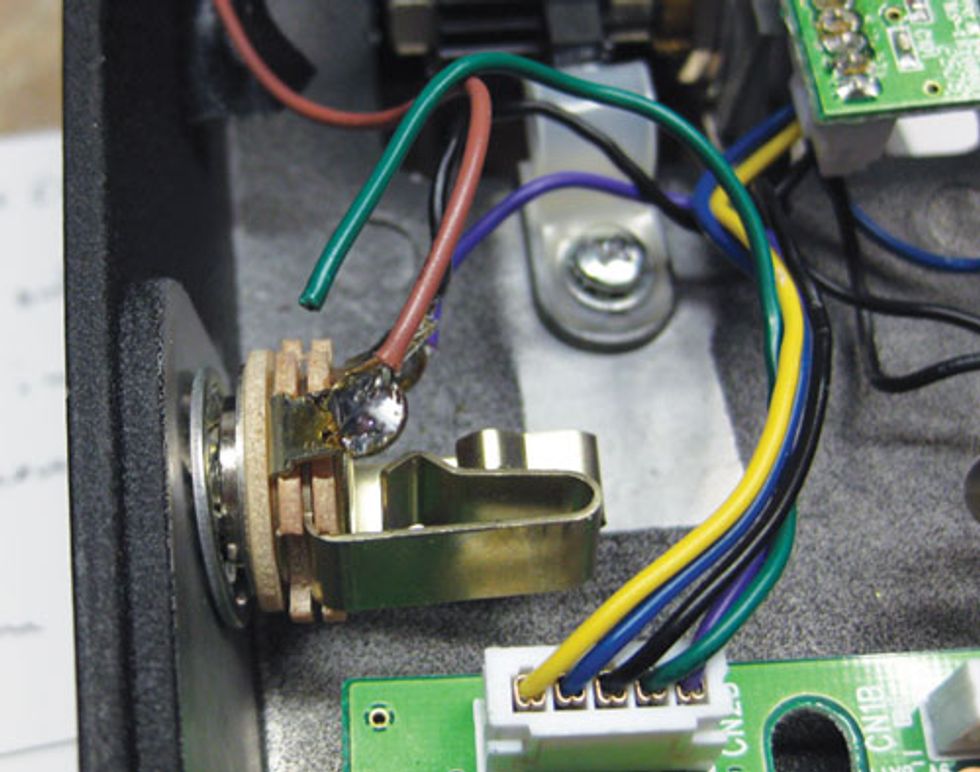
7. Brilliant! Your second mod is complete—take a bow! The wiring should look
something like the photos below.
MOD 3: ADDING A FASAL INDUCTOR TO A WAH
Mod Type: Tonal
Difficulty Level: Easy
What You Need:
• Soldering iron
• Solder
• Solder sucker
• Fasel inductor
Mod 3 is a wah-specific affair. We’re
going to swap out the existing
inductor and replace it with a Fasel
inductor. Technically, a wah is a bandpass
filter—a boosted bump of frequencies,
all of which are slid up and down
by depressing the expression pedal. The
heart of this effect in many wah pedals
is the inductor, so replacing it can result
in a different sound. “Different” does
not necessarily mean “better,” though.
If you Google this issue, you’ll see a lot
of talk about how great a Fasel inductor
sounds, but there are various flavors
of Fasels available—including a classic
’60s-style inductor (à la Hendrix) or
a ’70s disco-/porn-style affair. Choose
wisely, young Jedi.
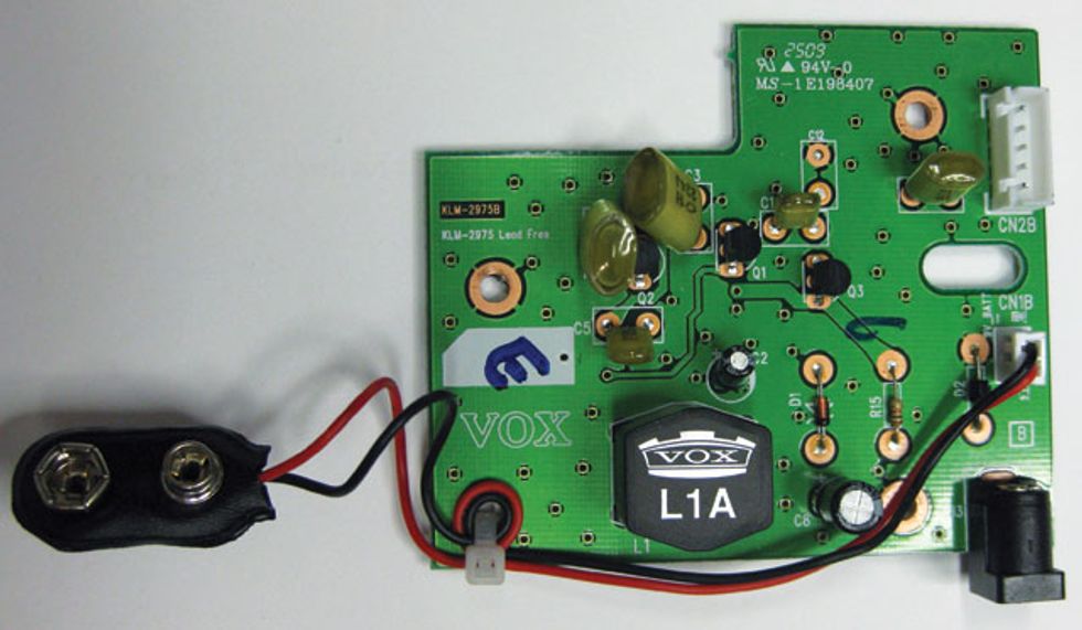
To install the new inductor:
1. Remove the wah’s main circuit
board by unplugging the white
plug with five wires attached to
it, and then gently pulling the
board out of the pedal’s housing.
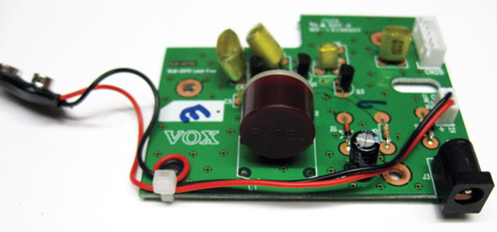
See the black thing with the Vox
logo and “L1A” written on it?
That’s the inductor.
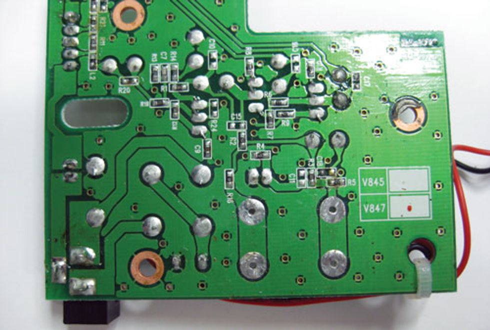
2. Turn the circuit board over, identify
the solder pads that connect to the
inductor, and desolder them.
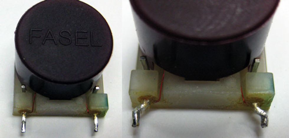
3. Gently bend out your new Fasel
inductor’s legs (right photo) so they’ll fit through
the inductor socket’s holes.
4. Pop the new inductor into the circuit
board and resolder the connections.
5. Place the circuit board back in the
pedal housing.
6. Plug the five-wired white plug back
into the circuit board. You’re done!
MOD 4: TRUE BYPASS SWITCHING
Mod Type: Tonal
Difficulty Level: Medium
What You Need:
• Soldering iron
• Solder
• Spare wire
• Insulation tape OR
heatshrink tubing
• A 2-pole/double-throw
or 3-pole/double-throw
stomp switch
• Wire strippers
• Side cutters
• Short piece of tinned wire
• Wrench for footswitch nut
Our final mod is adding true-bypass
switching to the same Vox wah from
mods 2 and 3. Although we’re demonstrating
this procedure on a wah, it can
be applied to any pedal—as long as you
can isolate the input- and output-socket
wires, and the circuit input and output
wires, and follow the instructions below.
I started writing the pros and cons of
this mod but swiftly realized such an essay
could fill a page or so. There’s plenty of
info on it out there, so if you’re inclined to
dive into the minutia, go forth and do your
research. My take on it is that true-bypass
switching is great—but you always need
to make sure you have one pedal in your
signal chain with a good, quality buffered
bypass if you’re running long lengths of
cable between your guitar, pedals, and
amp. It all has to do with impedance. The
low-impedance output of a good, buffered
bypass pedal means you won’t get any high
frequency loss using long cables.
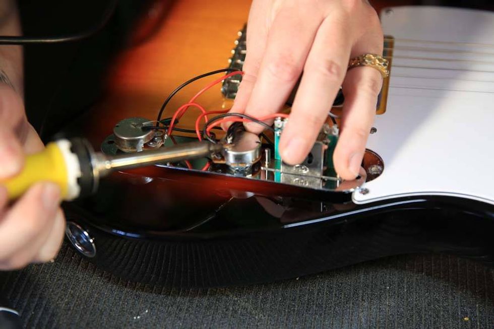
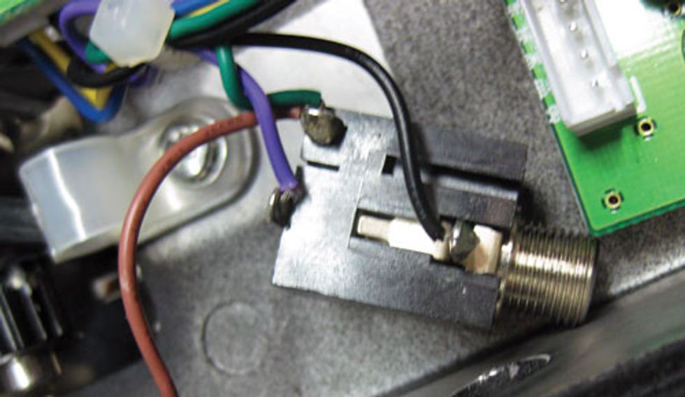
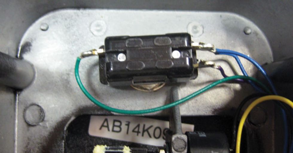
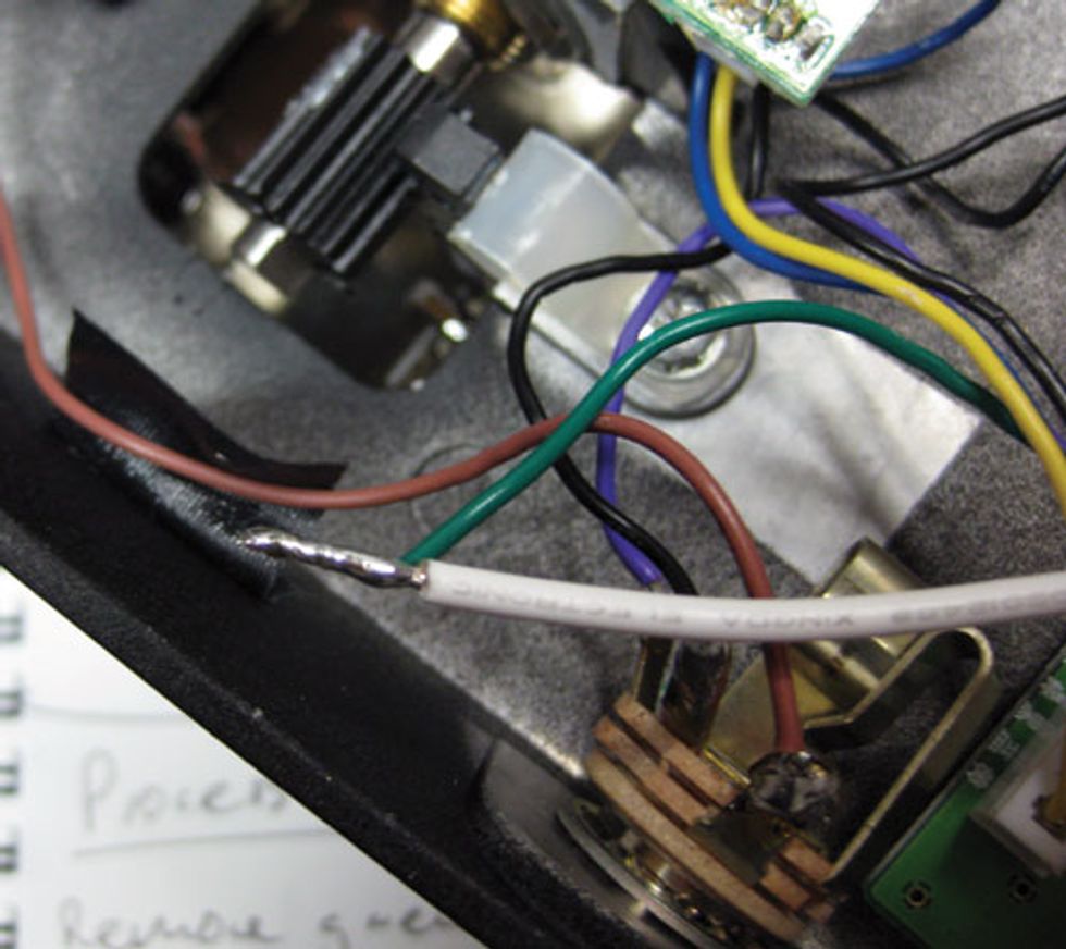
So, let’s turn our Vox into a true-bypass
device. First, let’s have a look at the existing
footswitch—the black rectangular box
connected to the brown, white, and blue
wires (shown below).
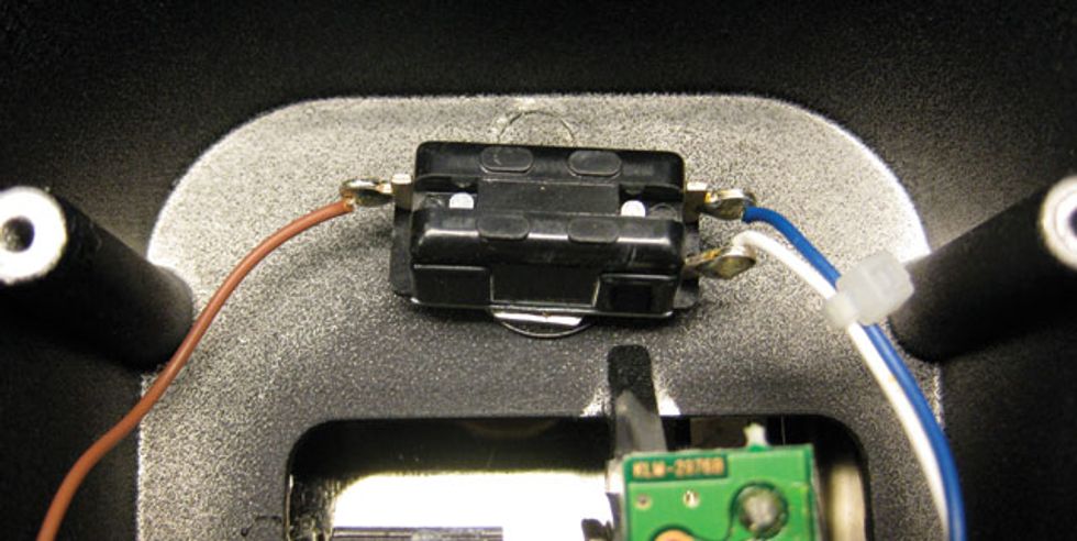
The brown wire comes from the input
socket, while the white wire goes to the output
socket, and the blue wire comes from
the circuit’s output. For those of you who
have a Jim Dunlop Cry Baby wah, here’s a
pic of its switch.
The color code for a Cry Baby is as follows:
The green wire comes from the input
socket, while the purple wire goes to the
output socket, and the two blue wires connect
to the circuit’s output.
Okay, back to our Vox wah.
To remove the old footswitch and install
the true-bypass one:
1. Desolder all three wires.
2. Now look at the input socket.
See the two wires attached to the tip
tag—the brown and green ones? The
green wire is the audio-input lead for
the wah circuit. Clip it so that it’s no
longer connected to the tip tag.
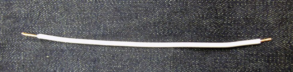
3. Take a 3"-4" spare piece of wire,
strip each end, twist the smaller wire
strands at each end together to create
a single, tightly formed lead, and tin
both ends with solder.
4. Strip the end of the green wire that
you clipped in step 2. Then twist
the green wire together with the new
piece of wire prepared in step 3. To
solidify their connection, solder
them together.
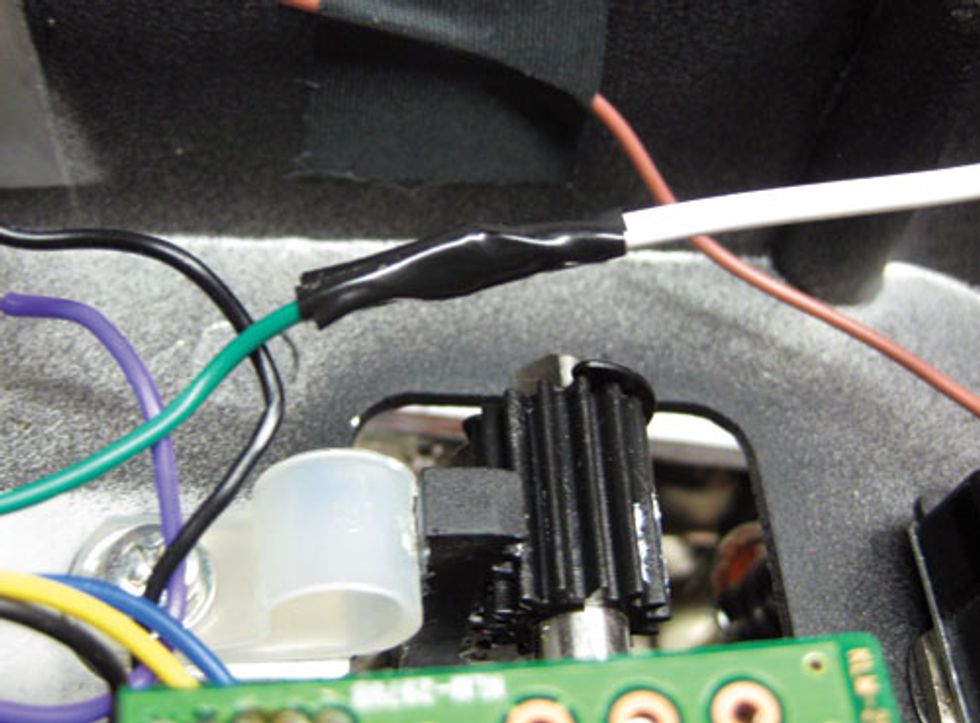
5. Insulate this cleverly extended bit
of wiring by either trimming and
applying an appropriate length of
heatshrink tubing OR wrapping
the exposed portion in insulation
tape, as shown below.
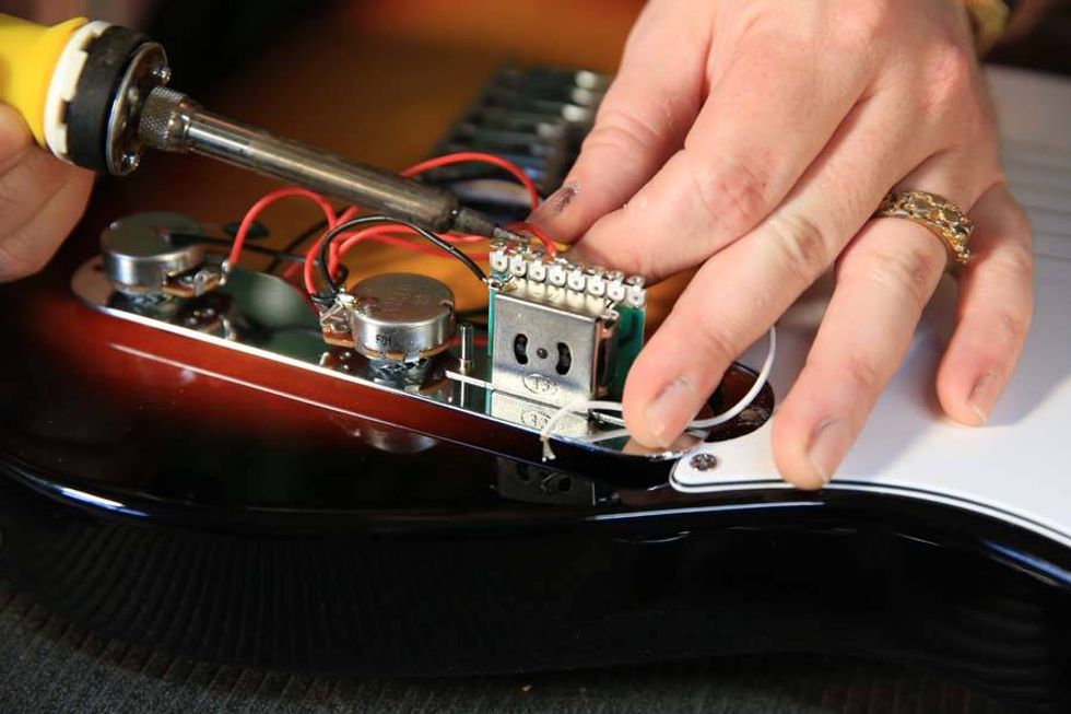
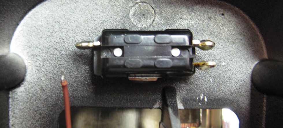
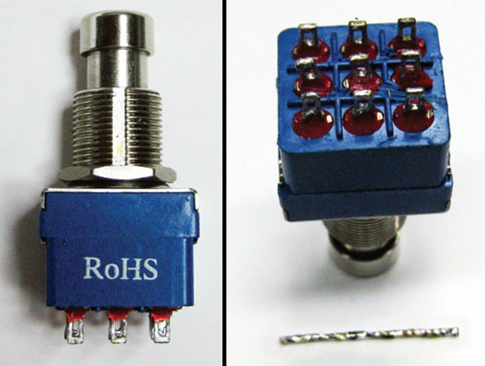
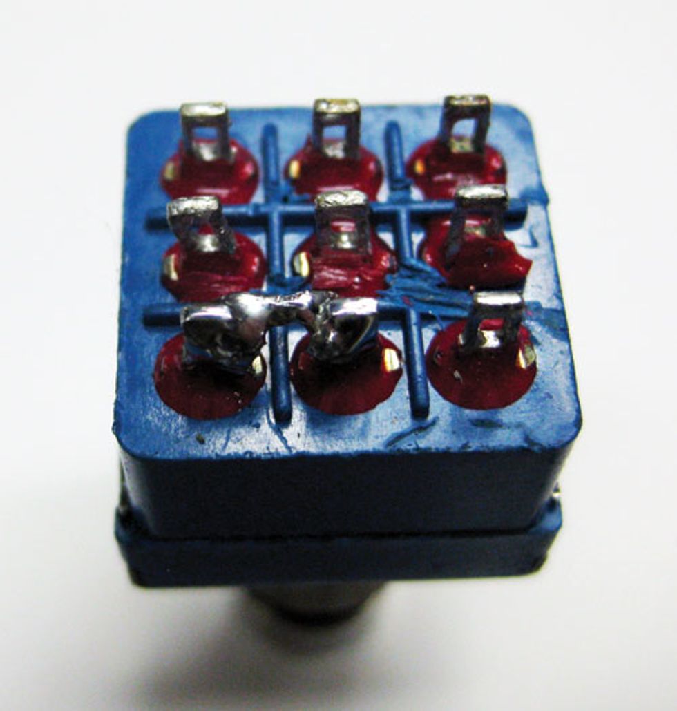
6. Now let’s take a look at our new
switch. Either a 2-pole/double-throw
or 3-pole/double-throw will work.
This one is a 3-pole/double-throw, but
we’ll only use two of the three poles.
Note the nine tags on the bottom.
(The piece of tinned bridging wire is
on the table below the switch.)
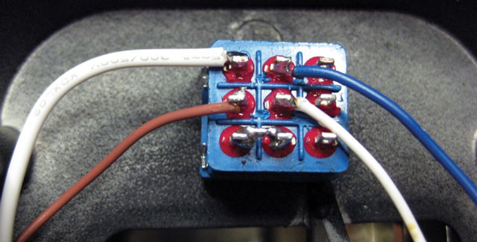
7. Position your switch so it’s in the
same orientation as the photo
above right—that is, with three rows of
three tags, with the holes facing you.
8. Solder a piece of the tinned wire
to the bottom left and bottom
middle tags.
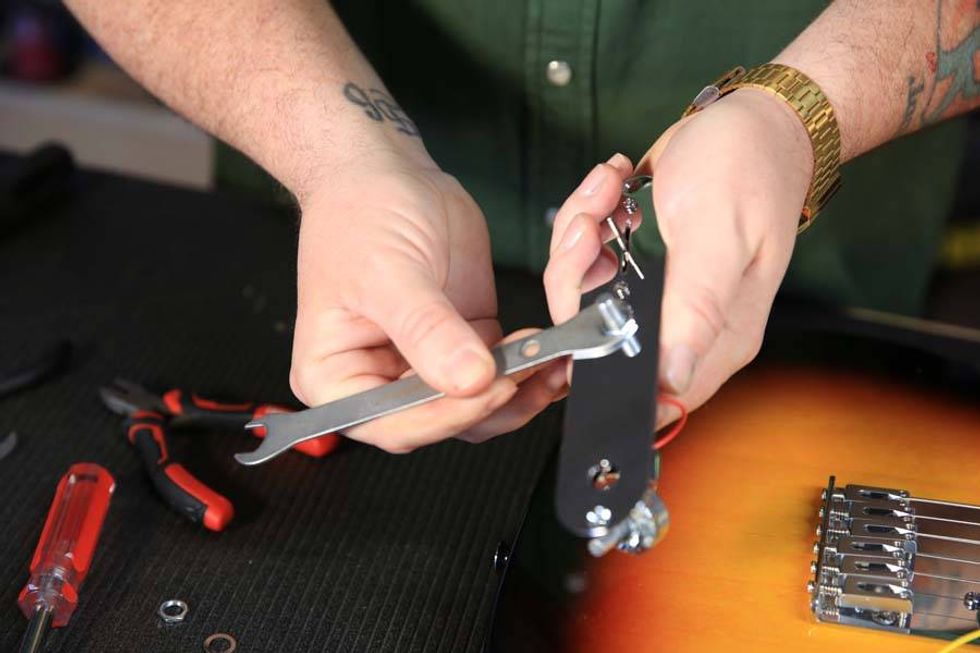
9. Fantastic. Now remove the old
footswitch and place the new
footswitch in the vacated space.
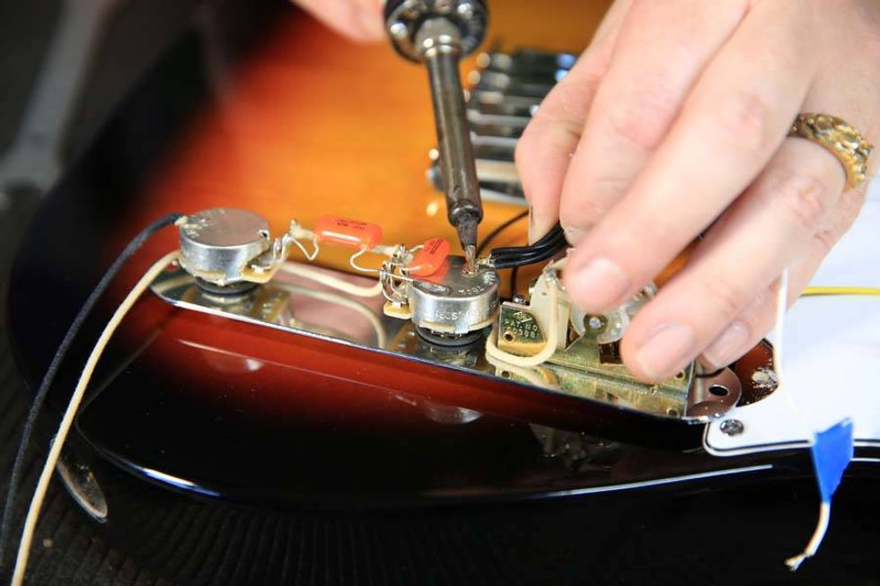
10. Solder the brown wire (which is from
the input socket) to the left-hand
middle tag.
11. Solder the white wire (from the
output socket) to the center tag.
12. Solder the blue wire (from the circuit
output) to the middle top tag.
13. Solder the extended wire created in
steps 3-5 above (which comes from
the green circuit-input wire) to the
left-hand top tag.
14. Marvelous—you now have true-bypass
switching! Your tags should
look like the pic below.
Go Forth and Modify
Although the four projects we’ve covered here are intended to be a simple introduction to the world of pedal modding, we’re confident that after you complete one or more and hear, see, or feel the difference it makes, you’ll be eager to do more. I recommend plugging into the giant super brain of the internet, which has a bounty of great mods available for the brave (of course, as with anything online, some are absolute tosh). As an initial port of call, I’d recommend geofex.com, fuzzcentral.ssguitar.com, and diystompboxes.com. Best of luck!