
Hello again, Premier Guitar readers! It’s your old bud Jeff here, author of the once popular Ask Amp Man column. Editorial Director Ted Drozdowski asked me if I would be interested in writing about bias, and, of course, I said, “Sure, I know a thing or two about that!” So here I am, temporarily returning to these pages. Now, let’s get started.
What exactly is bias? Bias is prejudice in favor of or against … oh wait, wrong kind of bias. I think he wanted me to write about bias in a tube amplifier, which is far less polarizing.
Bias, as defined in the RCA Radiotron Designers Handbook, is “voltage applied to the grid [of a tube] to obtain a desired operating point.” Well, that is the most basic explanation, but for the most part it is good enough and pertains to the majority of tube output stages in our favorite tube guitar amps.
Setting the bias adjustment controls to these listed voltages in no way guarantees that your amp is properly biased.
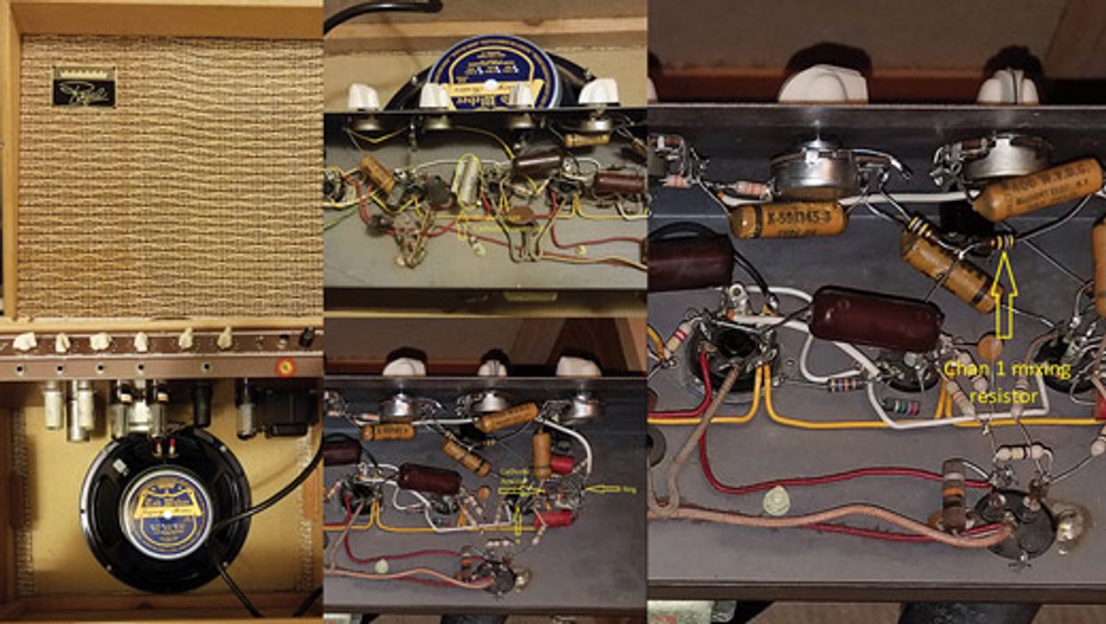
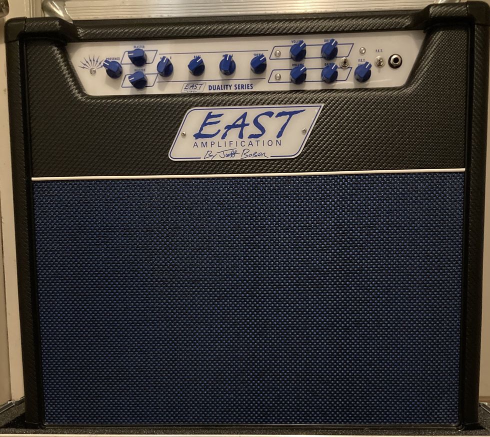
Besides “applying” a voltage to a vacuum tube, however, biasing can occur in another way as well. There are quite a few amplifiers, such as a Vox AC15 and AC30, any of my Budda and EAST designs, and even most of the early, low-wattage amplifiers of the tweed era that use what’s known as a “cathode bias” design. This is where the current flowing through the tube (which attains the aforementioned “desired operating point”) is not set by the voltage “applied” to the grid of the tube, but is instead set by the resistor in the cathode leg of the tube. It’s a bit more complicated than that, but the result is an amplifier whose output stage is “self-biasing.”
Most amplification devices, including transistors and even preamp tubes, need to be “biased” in order to perform properly, but this type of biasing is fixed in the design parameters of the circuit. In the case of the preamp tubes in your guitar amp, bias is based on the value of the cathode resistor, among other things. But that’s enough design theory for today. Let’s get back to the core task of biasing the output tubes in most guitar amplifiers.
First, the bias voltages you see listed on many schematics, such as 52V on a black-panel Fender Twin Reverb or 51V on a Marshall 100W Super Lead schematic, are merely approximations of the voltages that should be expected in that area of the circuit. Setting the bias adjustment controls to these listed voltages in no way guarantees that your amp is properly biased. Tube bias is also dependent on the high voltage (or B+) applied to the plate of the output tube, which can vary within tolerances of the transformers as well as in the AC line voltage fed to the amp. (This is why amps can sometimes sound better in one room or club than others.)
But even more important to understand is that tubes produced in different factories across the globe will bias up differently! What I mean by this is, if you properly bias a set of output tubes—let’s say 6L6s made in Russia—and then you swap them out with a set made in China, in the same amplifier without changing the setting of the bias control, the end result will almost always be a different bias reading. This is why it’s always best to have checked and reset the bias whenever output tubes are replaced. Now, how do we do that?
The Preferred Method
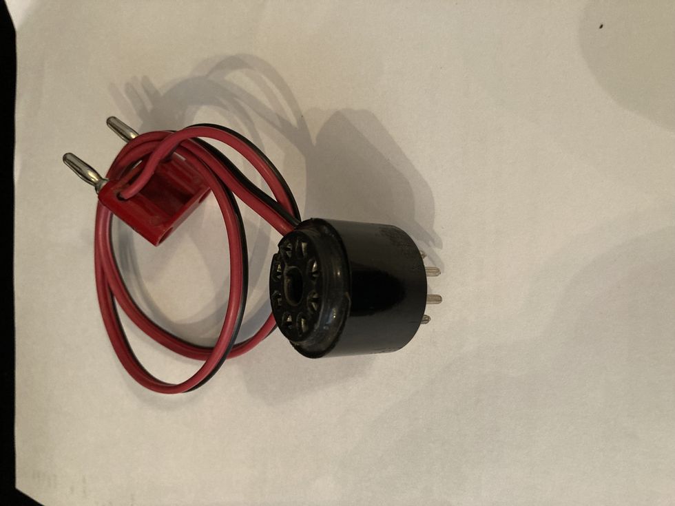
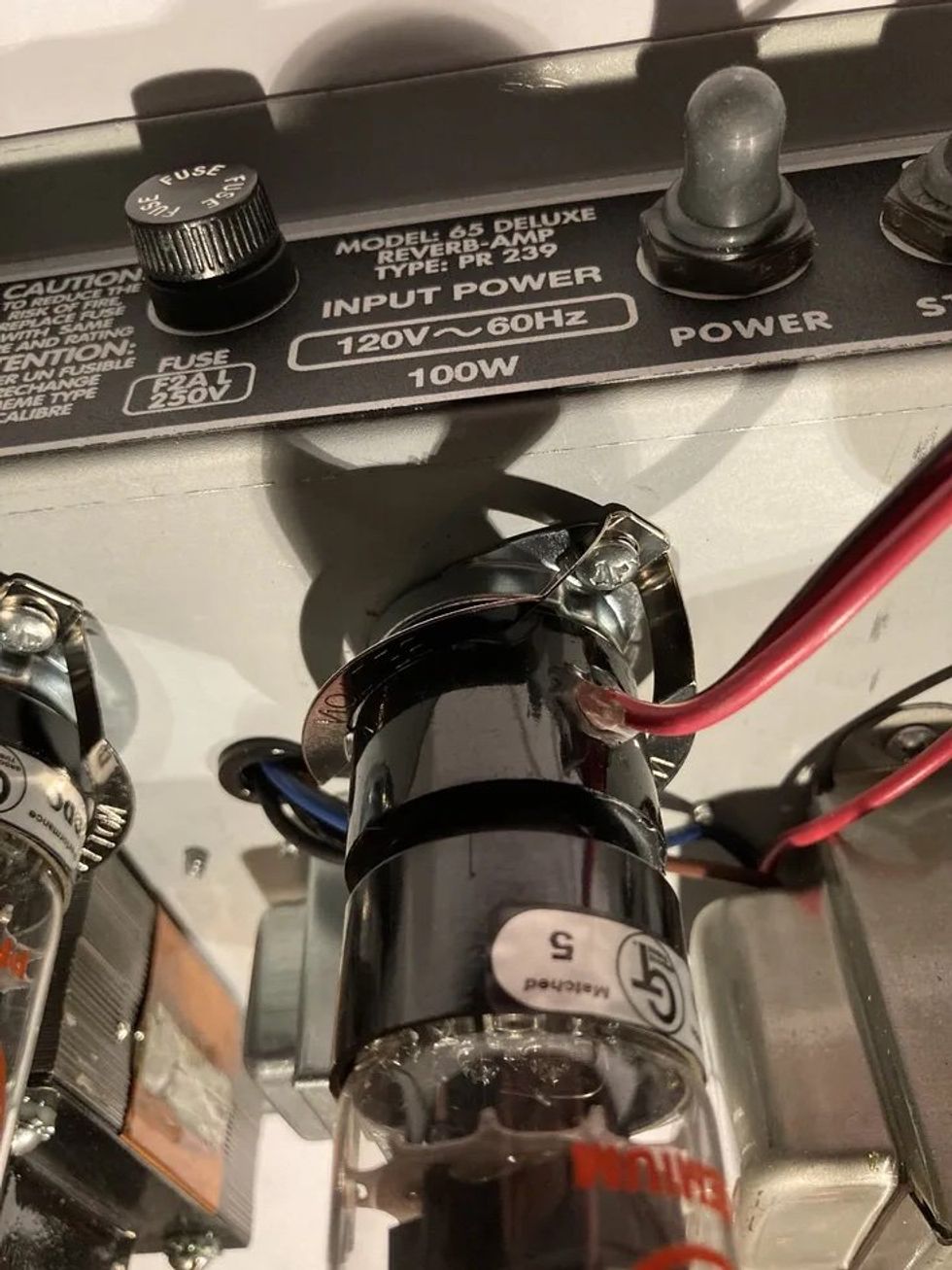
Fig. 1
There are several different ways to measure output-tube bias current at idle. The safest method is to use what is commonly called a bias probe (Fig. 1). This is a device that is inserted between an output tube and its socket. (I typically make my own bias probes, but if you simply search “bias probe” online, you’ll find plenty to choose from. If you already own a multimeter, you can simply purchase the probes, but there are also options to purchase a full system with either a digital or analog meter, should you need it.) This device breaks the connection between the cathode (which is the metallic electrode from which electrons are emitted into the tube) of the tube and its ground connection, and inserts a small value resistor in between. It then allows the voltage across the resistor to be read. The resistor is typically 1 ohm and the resulting voltage drop across it is in millivolts (mV), so no chance of shock here. This provides a true and accurate measurement of the actual current flowing through one tube. Then, you set your bias and you’re done!
But even more important to understand is that tubes produced in different factories across the globe will bias up differently!
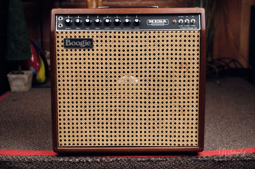
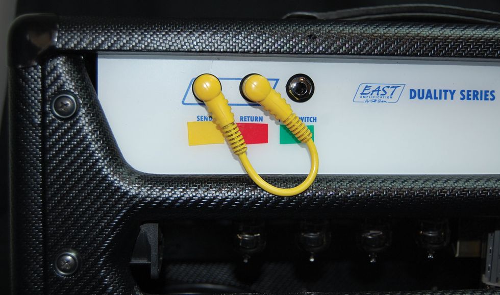
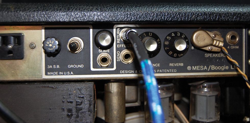
Ah, but wait! How do you set your bias? Let’s learn a bit more. Most tube amplifiers, if they are not cathode-biased designs, have some way to adjust the output-tube bias. One longstanding exception to this are most Mesa/Boogie amps. The bias voltage in these amps is not adjustable, which is why Mesa suggests only purchasing their tubes for their amps, because they are designed to fall within the acceptable bias range for their amps. This adds a certain degree of confidence for owner servicing, although, of course, it limits your options.
Let’s take a look, however, at a typical Fender or Marshall bias control. Most older Fenders have a pot with a slot for a screwdriver mounted to the chassis in the area of the power or mains transformer, while most older Marshalls have their bias pot mounted on the circuit board. (You might want to go online to look at schematics for your amp to help you find it.) Either way, this is where you’ll make your adjustment.
To get started, you’ll most likely need to pull the chassis and place it in a stable work environment. Insert the bias probe device between one of the tubes and the socket (Fig. 2). Make sure all the volume controls are set to zero, turn the amp on, and let the tubes warm up. It’s also good to try to have a load on the speaker jack—whether a speaker or an appropriate resistor or load box. This is not 100 percent necessary for just setting the bias to a particular number, but sound checking is one of the ways I like to make the final adjustments, so being able to connect the speaker to the chassis while it’s on the bench is certainly a necessity for me.
Now, where to set the numbers? There are certainly more than a few opinions floating around on the interwebs about what optimal bias settings are. Some engineering types will tout 50 percent maximum plate dissipation or 70 percent maximum dissipation, and while it may look good or make sense on paper, I’ve heard the result of guitar amplifiers designed by the book to optimal specifications … and to me they sound, well, less than optimal. It may work in the hi-fi world, where perfect sound reproduction is the goal, but guitar amplifiers are in the sound production business, so it’s a bit different. (In the most basic terms, maximum plate dissipation is the amount of power the plate of the tube is designed to deliver.)
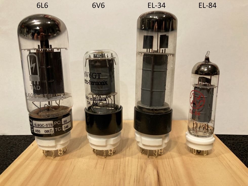
Different types of output tubes have their own acceptable range of bias current. There are so many variables at play that there is no “correct” number. The plate voltage in the amplifier, the output transformer’s primary impedance, and the country of origin of a tube all factor into how it interacts with the voltage and output transformer to define what the optimal bias current will be. Below are the average ranges for some typical octal output tubes:
• 6L6: 25–35 mA
• EL34: 30–40 mA
• 6V6: 18–25 mA
• 6550: 35–45 mA
• KT66: 30–40 mA
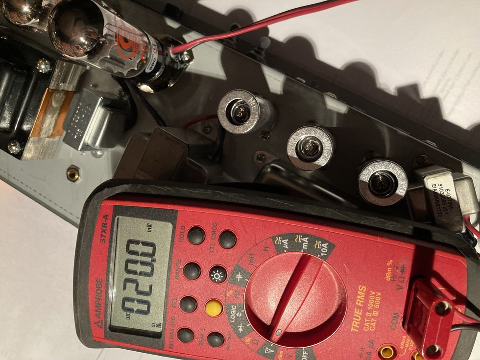
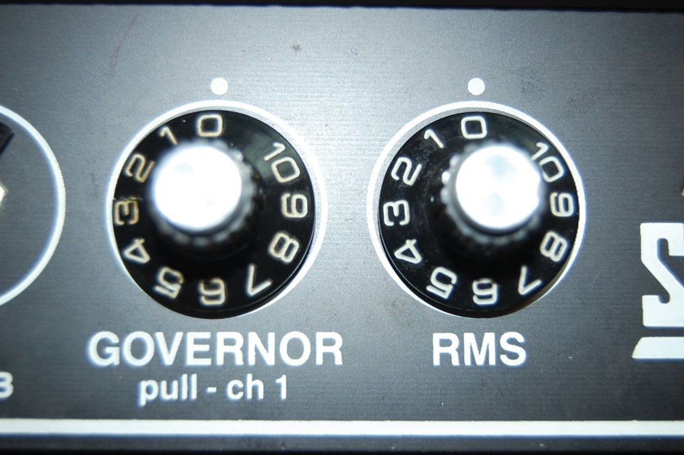
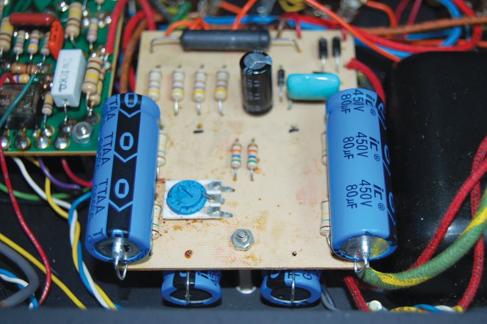
Fig. 3
These should be the ranges in which these tubes will perform and sound the best, and they can be accurately measured with a digital multimeter. The best way for you to decide what setting is best for you is a combination of the reading on the meter and your ears! Using the bias control, set the bias to somewhere in the ranges given above (Fig. 3) and play the amp. Note: Some amps will act funny and develop horrible noises (parasitic oscillations) when a bias probe is in place while the amp is being played. If this is the case, you’ll need to remove the bias probe each time you play the amp.)
Move the setting a couple mA in one direction or the other and play again. Don’t expect extreme changes; that’s not what we’re looking for. Listen for subtle differences. Is one setting a little more or less harsh? Is the bottom end too soft or flubby? Is the amp as clean as you want it? Sometimes these little subtleties are what make one amp sound and feel better than another!
Most older Fenders have a pot with a slot for a screwdriver mounted to the chassis in the area of the power or mains transformer, while most older Marshalls have their bias pot mounted on the circuit board.
Also, you should be doing this at the volume you would typically use onstage or in the studio. You may not notice much change if your volume is at 1, but you want to optimize the amp for the way you will be using it.
Eyes Wide Open
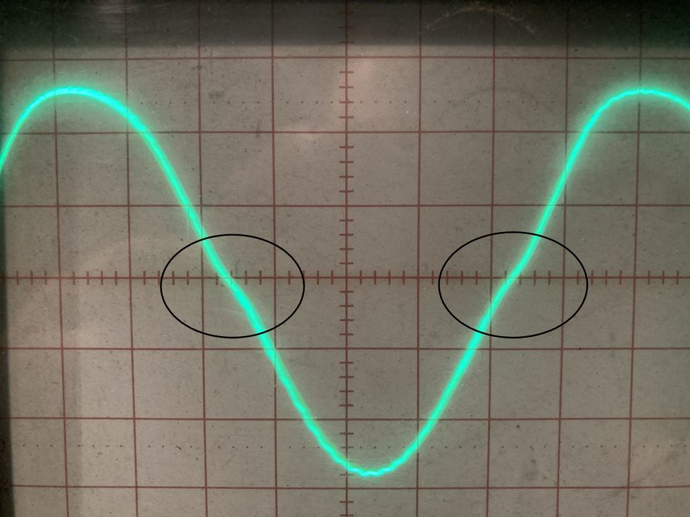
Fig. 4
Knowing the ballpark bias numbers is good, and adding your ears is even better, but I also like to see what I’m hearing, so I always incorporate an oscilloscope when I’m setting the bias on an amp. I mentioned crossover distortion above, and when it comes to setting up amps for today’s pedal-hungry players, I find that setting the bias to where there is just a hint of crossover distortion at full output is what works best. Fig. 4 is what that looks like on the oscilloscope. This keeps the amp very clean and makes most pedal users happy.
By the way, here’s a mini primer in crossover distortion. In a push-pull output stage, which is found in most amplifiers with two or more output tubes, each tube (or pair of tubes) is responsible for amplifying at least half of the audio signal. If the tubes are not biased properly, one tube (or pair) will stop amplifying before the other tube (or pair) start amplifying. This will create crossover distortion. Proper biasing will allow the two halves to interact correctly. It’s like a nice firm handshake between both halves.
Beware These Old-School Methods
Let’s look at a couple popular methods that I do not recommend, but are worth discussing because they are, nonetheless, common. The first is: With the amp off and output tubes removed, use a multimeter to measure the resistance of each half of the primary side of the output transformer. This would typically be from the center tap to each side of the primary winding.
In the most basic terms, a transformer is a bunch of wire wound around a steel core. On the primary side of an output transformer, the center tap is the electrical “middle” of this long length of wire. This is typically where the high voltage is applied. The ends of this length of wire are connected to the plates of the tube, thereby applying the high voltage to the tubes. As an example, typically in most Fender amps, the center tap is red, and the ends of the primary windings are blue and brown.
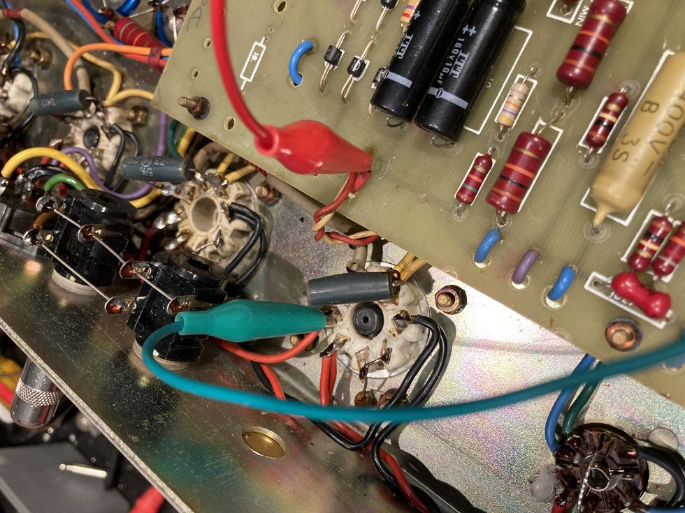
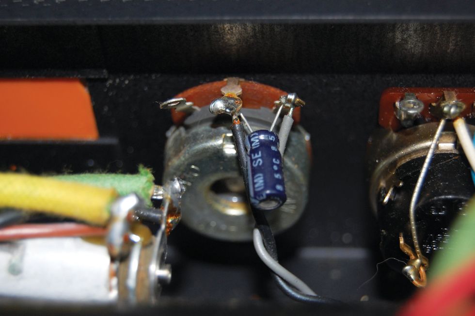
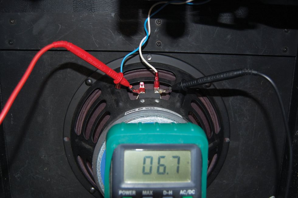
Fig. 5
Next, install the output tubes, turn the amp on, and measure the voltage drop across each half of the output transformer with the amp at idle in operational mode (Fig. 5). Voltage divided by resistance will give you the DC current through the tubes. For example, 1.17V / 15.8R = 0.074, or 74 mA. The numbers I used here were actual measurements in one side (one half) of a 100W amp using four output tubes (two per side). So, divide the 74 mA by two, and you get an average of 37 mA per tube.
Next, you can try the shunt method. This requires a multimeter that can read DC current in milliamps (mA). Connect one meter lead to the center tap of the output transformer and the other lead to the output transformer’s primary side. Typically, in most amps using octal tubes (6L6, 6V6, EL34, 6550, KT88, etc.), this will be pin 3 on any output tube socket. Turn the amp on and, in operating mode at idle (i.e., volume off), measure the current across that half of the output transformer. For example, if your measurement is 72 mA and it’s an amp that utilizes four output tubes, the current measured is for two of those tubes, so once again divide by two to arrive at 36 mA per tube.
I’ve heard the result of guitar amplifiers designed by the book to optimal specifications … and to me they sound, well, less than optimal.
Both of those methods are very old school and still in practice, but I wouldn’t use either for two reasons: 1) I don’t believe they’re very accurate, and 2) they’re dangerous! You’re probing around inside the high voltage area of the amp, and one slip will either take out a fuse, take out a tube, take out your meter, or, worse case, let you know exactly what 450V DC feels like! So, although these methods are used, let’s just say no here.
Some Personal Insights
I’d also like to add a little personal experience to this procedure, based on decades in the biz. Back in the day, when I began servicing and modifying gear, guitarists were regularly playing 50- and 100-watt amps. (Everybody looked at me like I had three heads when I came out with the 18-watt Budda Twinmaster, but that’s a whole other story.) There were some overdrive and distortion pedals around (now all vintage), but certainly not the pedal proliferation we have now, so players were pretty much guitar, cable, amp … go! In these situations, I would most times run the tubes with a pretty hot bias so the amp would be fatter and overdrive a bit earlier and easier, as a decent percentage of the overdrive was developed by pushing the output tubes. As time went on, output attenuators became more popular, so amps could be pushed hard, but at more manageable volume levels. That was still a good scenario for a hotter bias of the output tubes in high-power amps. Eventually, players started playing lower-power amps, so they could open them up and get great output-tube distortion at lesser volumes. The problem is that hotter-biased low-power amps tend to get mushy and have less definition when pushed hard, so a more moderate bias setting is preferred here—just enough so there is no crossover distortion. Move up to today’s scenario and you’ll find that almost all overdrive and/or distortion is typically coming from a pedal. In that case, an amp is nothing more than an amplification device for pedals.
So, that’s what I’ve learned about tube-biasing from my decades of experience. But the bottom line is, there is no absolute right or wrong settings when it comes to biasing an amp. Keep your ears open and go with what sounds best to you.