  |
| I recently purchased an amp and would like a little more information about it. It is a West Mini IR. It has two 6CA7s, two 12AT7s and two 7025s. By looking at the photo of the chassis, can you tell if this is Class A or AB? Is it based on something else, like a Fender or Marshall? The amp sounds great and is surprisingly loud. I had to replace the switch, but as far as I can tell nothing else has been done to it. Thanks for any info you can give me. Andy Rhodes Wilkesboro, North Carolina |
Hi Andy,
Thanks for your question and the cool pictures of the amp. I haven’t seen a West amp since Mark Farner played them in Grand Funk Railroad in the seventies! They were designed by a gentleman named Dave West in the late sixties and early seventies, and while I’ve seen the head/cabinet configurations, I’ve never seen this particular combo. Since a picture is worth a thousand words, let’s see if I can give you some insight into your amp, based on the pictures you’ve sent.
Your observation of the amp being stock except for one of the switches is almost correct. What used to be the Polarity switch is now the Power switch, and the original dual purpose Play/Standby/Off switch is now simply a Standby switch. In addition, one of the diodes in the power supply has been replaced. Other than that, the amp – especially all of the components in the audio path – appears to be stock. That means the tone and response of the amp should be as it was designed.
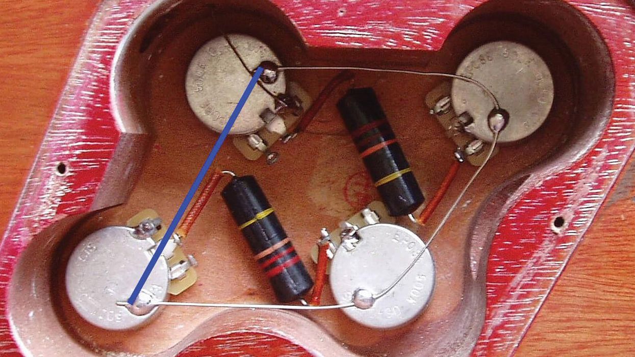
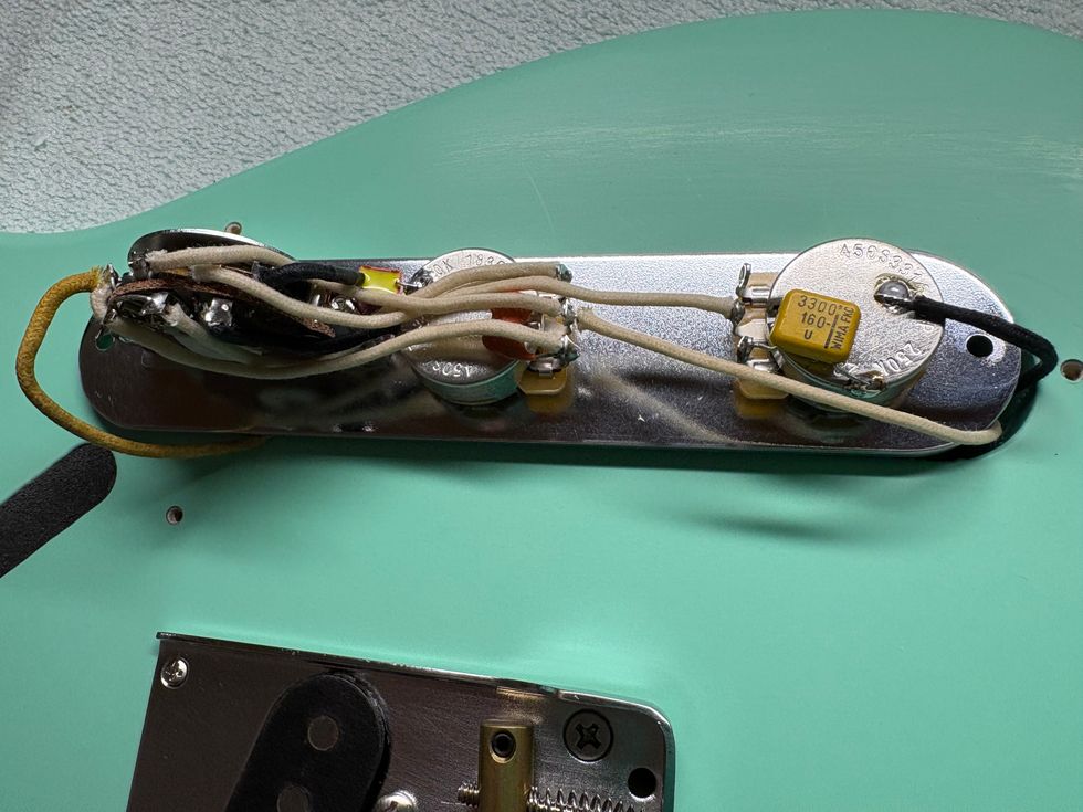
I can tell by looking at the open chassis picture that the amp’s design is very Fender-like. The 1.5K resistors in parallel with what I’m assuming are probably 25” capacitors on the cathodes of the first preamp tube are very indicative of this. Additionally, the output of the first gain stage goes to a pre-volume plate-driven tone stack configuration, as opposed to the post-volume cathode-driven tone stack found in most Marshalls of this era. There’s also a Bright switch tied to the Volume control, which is very Fendery.
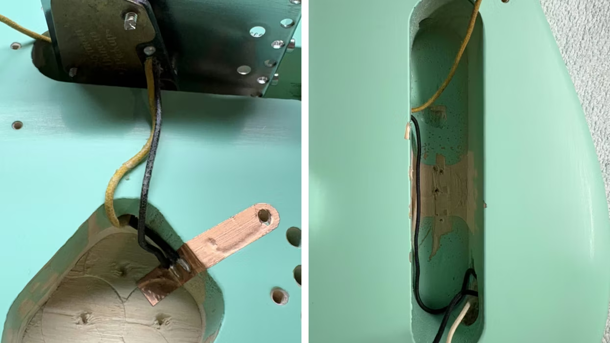
From there, the signal goes to the reverb, drive and mix circuits. The transformer-driven reverb tank has the transformer mounted on the circuit board, as opposed to being chassis- mounted. This allows the transformer to be part of a “module” build, rather than being wired through the chassis – a nice construction option. The 2.2K resistor in parallel with a capacitor (probably 5-25”) on the cathode of the reverb drive tube, along with the 3.3M resistor paralleled with a small, ceramic capacitor as part of the “mix” circuit, are all in line with the typical “Big F” design constants of the era.
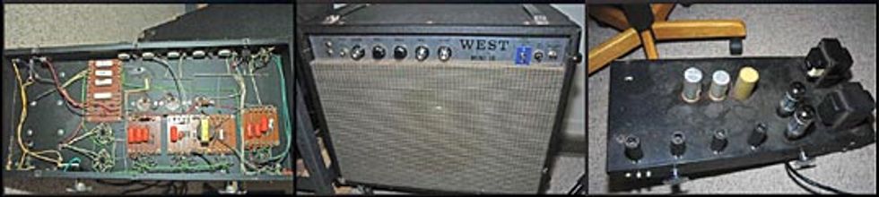
From there the signal goes to the phase inverter circuit. This is a pretty standard type of circuit for most manufacturers, but with a 22K resistor in the cathode circuit and the lack of a presence control, the circuit definitely leans toward a Twin tonality, rather than its British counterpart. The signal is then coupled with the bias voltage and sent to the output tubes. The output stage more than likely utilizes a standard A/B bias, which is supplied by a non-adjustable “fixed bias” circuit. This can, if necessary, be converted to an “adjustable” fixed bias circuit simply by having the 15K resistor, which is in parallel with the 50” 75V cap on the power supply board, replaced with a series resistor and potentiometer.
Although the amp seems to be pretty typical in many ways, I do see a couple of design features here that set it apart from the amp I’ve been using as a comparison. First, the filament (heater) of the first preamp tube is powered by its own 12VDC supply, generated by a unique voltage-doubler circuit on the power supply board. This is done to eliminate filament hum in the first gain stage of the amp, and in this era would be found more in hi-fi gear than in guitar amps. I think it’s a very cool improvement.
Next, the output transformer is of the ultralinear type. It not only connects to the plates of the output tubes, as most output transformers do, but also to the screen grids via a special set of taps. These transformers, very generally stated, enable an amp to have a louder, cleaner output. This may or may not be appreciated by guitar players that actually want the output stage of their amp to generate a bit of grind and distortion, but if you’re looking for big and clean, this is a good option. Again, this stems back to a hi-fi approach to design, but it can definitely work well in some guitar applications.
Well, there you have it. About a thousand words of description on your amp from a picture. Now you’re all set to join a Grand Funk tribute band. Enjoy.
Jeff Bober
Co-Founder and Senior Design Engineer – Budda Amplification
jeffb@budda.com
www.budda.com
©2007 Jeff Bober