
I'm often asked about tube rectification in guitar amplifiers. For many players, it's a subject that could stand a little deeper scrutiny from an engineering and design perspective. First, keep in mind that a tube rectifier is not an audio amplifying device. If no audio signal passes through it, how does it affect an amplifier's sound? Let's have a look.
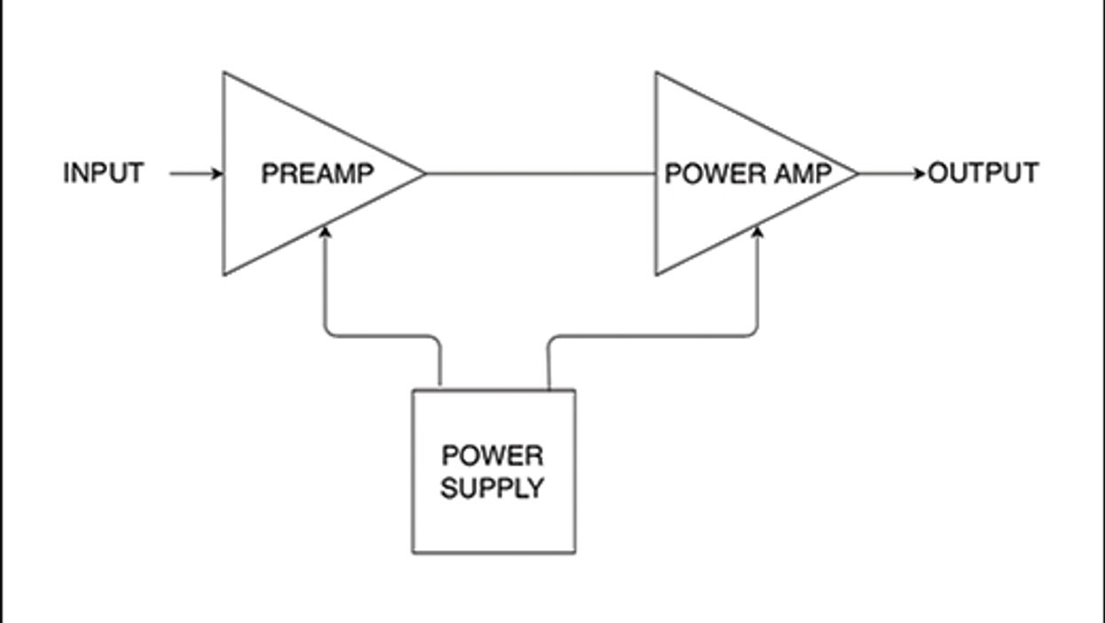
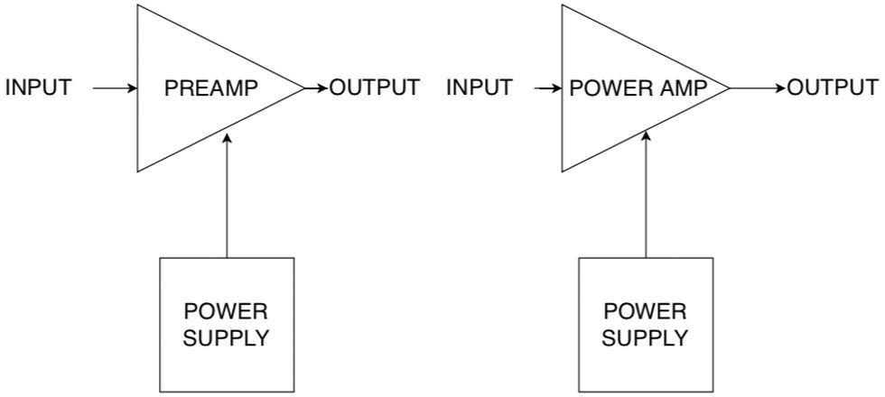
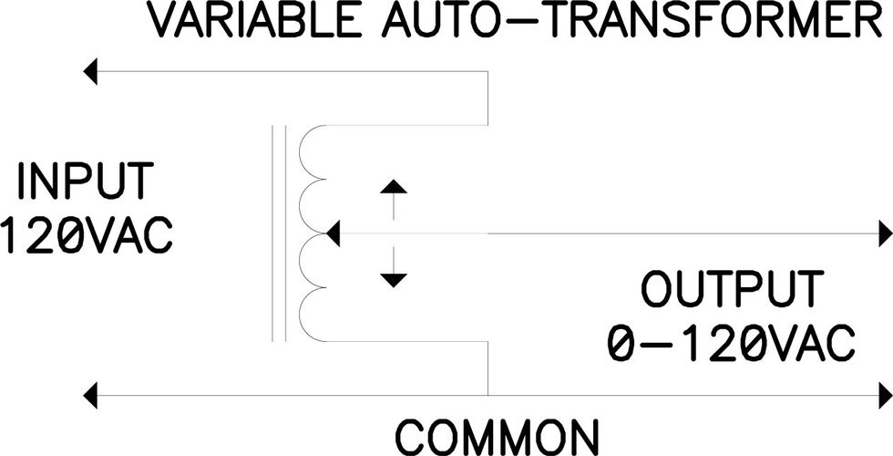
Your amplifier's preamp and power tubes require a DC voltage to operate. The amplifier's power transformer converts the incoming AC line voltage to the levels required. The power supply rectifier, whether of the vacuum tube or silicon diode variety, converts the AC voltage to DC. That DC voltage is filtered and then sent along to the various amplifying stages to do their specific tasks.
The hard-working power supply must be able to deliver the amplifier's maximum continuous rated power for an extended period of time. Most well-engineered amplifiers can operate continuously at full power for hundreds of hours without generating sufficient heat to injure the operator or cause a component to fail. Even so, things do heat up.
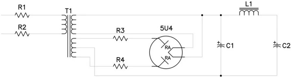
A rectifier tube in a typical tube-rectified power supply: R1 and R2 represent the internal copper resistance in the transformer's primary winding, and R3 and R4 represent the same in the transformer's secondary winding. RA represents the tube's internal resistance between the anodes and the cathode. In a silicon-rectified power supply, RA is much lower and therefore produces less heat loss.
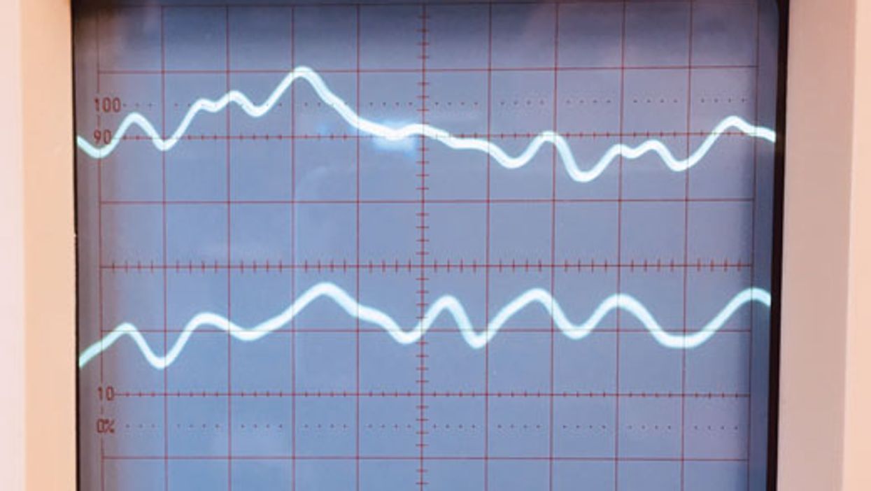
When you play at low volumes, you're not placing a great demand on your amplifier's power supply. At gig volume, however, you start drawing significant power from it. When you run the unit for several hours straight, the copper wire in the power transformer gets hot. Copper wire, being an imperfect conductor, exhibits resistance to current flow, and this inherent resistance causes the wire to heat up as the power demand increases. The resistance of a given length of wire is fixed, which means something has to give when the temperature goes up, and that something is voltage. As your power transformer heats up, the voltage it produces decreases. In a typical amp this decrease isn't large, but it's noticeable.
When we introduce a tube rectifier into the equation, the effect of heat-induced voltage loss is exaggerated. The reason is that the rectifier also has some internal resistance that contributes to a total drop of as much as 50 volts under full load. That's a lot. Silicon diodes overtook vacuum-tube rectifiers long ago because they were much less expensive and assembly was less labor intensive. But there was another reason: They're more efficient, due to low internal resistance. That difference in internal resistance means silicon and vacuum tube rectifiers are generally not directly interchangeable. Using a plug-in silicon device in place of a tube rectifier can cause excess DC to appear at the filter capacitors.
When you play at low volumes, you're not placing a great demand on your amplifier's power supply. At gig volume, however, you start drawing significant power from it.
A tube rectifier may make the cut when the goal is to produce a vintage-correct reproduction amp. Even though we can engineer a similar amount of voltage sag into the power transformer, purists may see the absence of the original part as a cop-out to save money, when, in fact, it may simply result in a more reliable, maintenance-free design. However, inducing sag into the transformer design can cause the temperature in the power transformer to increase more rapidly over time, in which case a larger, heavier, and more expensive part may be required to manage this drawback. In some cases, getting a power transformer design to conform to modern regulatory limitations can be simplified by using a tube rectifier to provide an easier path to safety compliance. We often see reissue amps that differ in performance from the originals simply because they have to clear regulatory hurdles that were non-existent at the time the originals were created. A crafty engineer can often find workarounds to such obstacles, and clever application of transformer technology and tube rectification are valuable tools in the kit.
In my experience, the most practical use of a tube rectifier is in dual-voltage power supplies, where a high- and low-power mode is required. For the high-power mode, a large, stable power transformer is necessary to meet maximum performance parameters. The downside? A high-capacity power transformer tends to yield stiffer performance when not running at or near maximum potential, such as in a low-power mode. This is where the tube rectifier really shines: It can be used to exaggerate the voltage sag in a power supply that would otherwise exhibit an unforgiving feel.
Whether the design objective is aesthetic, practical, or genuinely novel, it's good to have choices. Besides the satisfaction of seeing more glowing tubes humming away in our amplifiers, it's nice to know that players appreciate the extra effort involved in creating new designs around these familiar bottles.
[Updated 10/14/21]