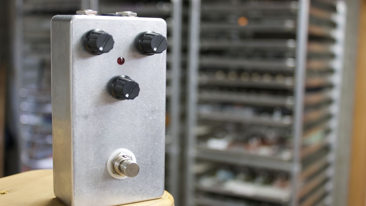
The finished BYOC Classic Delay kit (Photo 1).
Never kit-built a stompbox? It’s easy—if you let pro pedal maker Alex Guaraldi of CopperSound be your guide. Here, he takes you on a step-by-step tour as he assembles a Build Your Own Clone Classic Delay.
For this DIY adventure, we’re going to be walking through the steps of building the Classic Delay pedal from Build Your Own Clone (BYOC), a company that has been a big player in the pedal-kit game for quite a while. This is a little more complicated than building a fuzz or overdrive, so I’m going to explain the process with great detail. Let’s get started.
Tools You’ll Need for This Project
- Soldering Iron
- Solder
- #2 Phillips screwdriver
- Wire strippers
- 8 mm (5/16") nut driver/wrench
- 10 mm (25/64") nut driver/wrench
- 1/2" nut driver/wrench
- 14 mm (9/16") wrench
- Flush cutters
- Small needle-nosed pliers
- Third hands
These tools are available via a variety of suppliers, including StewMac, Allparts, and Amazon.
Step 1: Review the Instructions
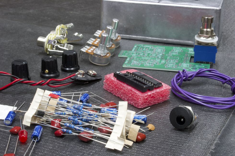
The kit as it arrives (Photo 2).
Each BYOC kit comes with a detailed set of instructions in the form of a PDF that can easily be printed out. The Classic Delay’s instructions can be found at https://www.byocelectronics.com/classicdelayinstructions.pdf. They are 32 pages long, and I suggest following their steps as you read this article. Here, I will refer to specific page numbers that correspond with the steps. I’ve also taken photos to coincide with the steps. Within the instructions, we find a table of contents, pictures of the fully assembled pedal, a list of parts included, and step-by-step instructions from internal population and soldering to external assembly. With any kit, always read the instructions carefully before you start building.
Step 2: PCB set-up
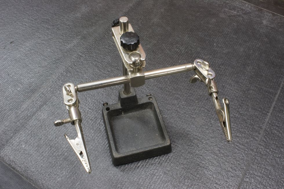
Photo 3
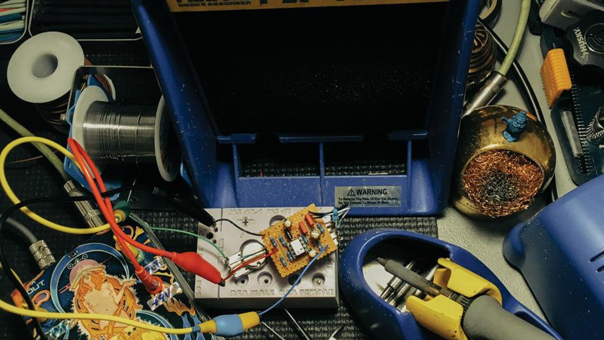
A lot of pedal builders use PCB jigs that are specifically designed to hold several printed circuit boards so that they can be easily populated and soldered. These jigs are great tools. However, they’re not something a casual DIY enthusiast will often have. Essentially, all we really need to do is elevate the PCB off of the working surface so that the leads of the components can pass through the bottom side of the PCB. This is most helpful with components that can be soldered from the top side of the PCB. “Third hands” or “helping hands” (Photo 3) are a good tool for this job. So, what can we do to elevate the PCB if we don’t have access to third hands? Simply turn the enclosure upside down and place the PCB perpendicular (Photo 4). This will elevate the PCB enough to allow the component leads to easily pass through.
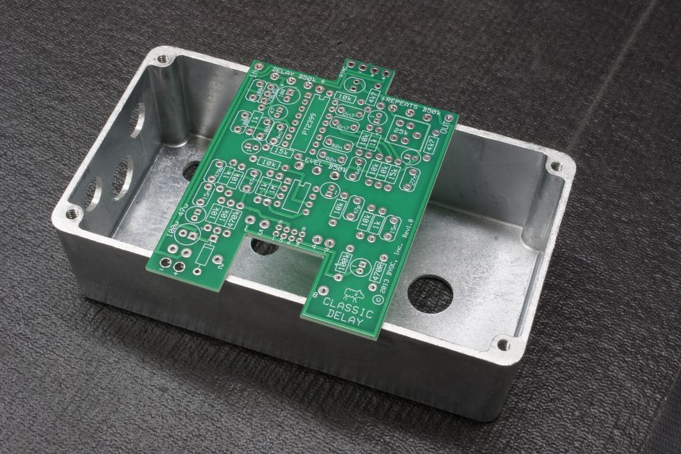
Photo 4
Step 3: Populating Resistors and Diodes (instructions page 9)
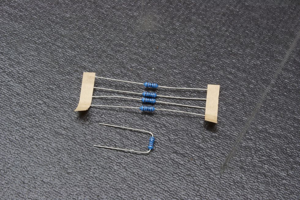
Photo 5
When populating PC boards, we typically like to work lowest to tallest in regards to the seating. Seating is how far above the PC board the component rests. Resistors and diodes sit pretty low to the PC board, so populating them first makes sense.
Resistors: Remove the resistor from the paper ribbon, bend the leads (Photo 5), and place them through the corresponding pads (Photo 6) as directed. (A pad, by the way, is the term for the designated surface area of a component’s electric contact point.) A good practice is to populate all resistors of the same value before moving on to the next value. Populate all 1k resistors, then all 10k resistors, and so on.Photo 6
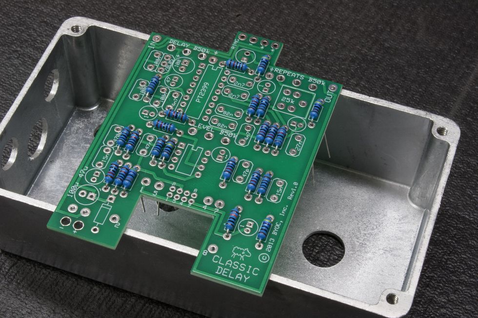
Reading resistor color bands can be confusing, so don’t forget the reference guide on page 7 of the instructions. Here, you will find a detailed breakdown of each value and its corresponding 5-band reading (i.e. 1k = brown/black/black/brown/brown). Once all the resistors are placed, we can go on to the diode.
Diode: Next, we need to place the diode. Just like resistors, remove the diode from the paper ribbon, bend the leads, and place them through the corresponding pads. Diodes are polarized and need to be oriented a certain way (Photo 7). Be sure to match the diode to the outline on the PCB, as shown on page 10 of the instructions.
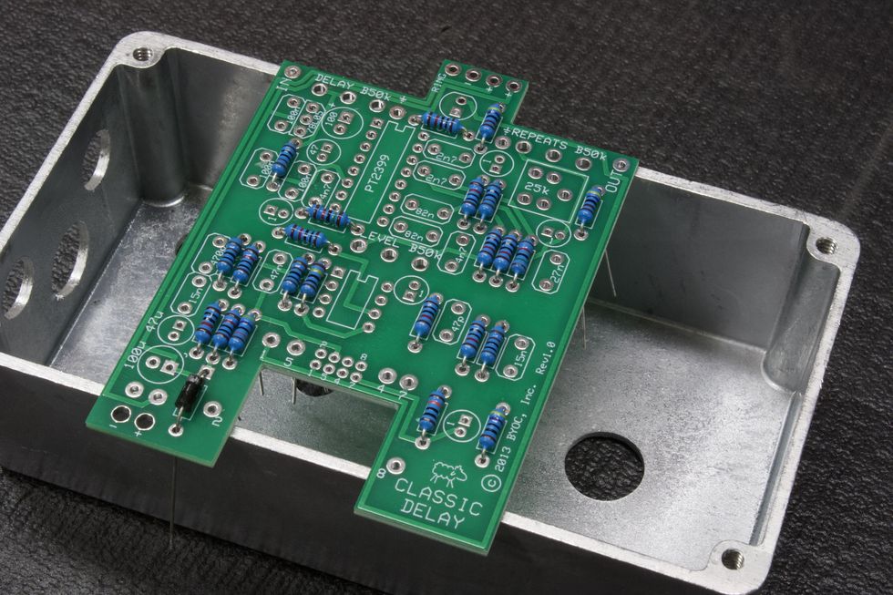
Photo 7
Step 4: Solder Resistors and Diode
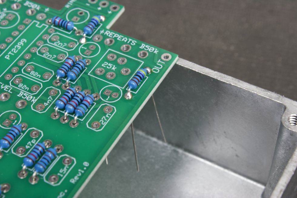
Photo 8
Fire up the soldering iron! Once the iron is up to temperature (650 to 750 degrees Fahrenheit, depending on how fast you work), it’s time to get to work. Resistors and diodes can easily be soldered from the top side. So no need to flip the PCB over. Place the solder tip to the pad and feed the end of the tip a bit of solder. What we’re looking for here is solder that covers the entire pad, encapsulates the lead, and has a nice shine to it. Think of it like a shiny Hershey's Kiss shape (Photo 8). Repeat this step for every part. If you’re new to soldering, you should consult our concise guide to soldering, online or in PG’s October 2015 issue.
Soldering tip: Shut the iron off between population steps. Use a small, tabletop fan to blow the solder fumes away during soldering steps. Quick tutorial videos on YouTube are also of benefit here, for builders new to soldering.
Step 5: Trim the Leads
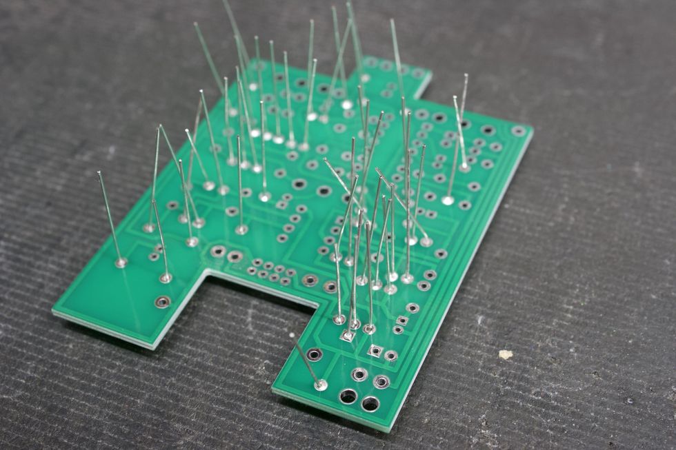
Photo 9
Next, place the PCB upside down to expose the leads (Photo 9). Using flush cutters, trim the excess leads (Photo 10).
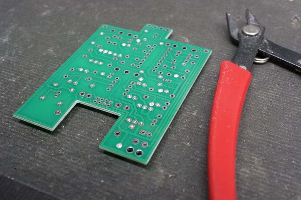
Photo 10
Step 6: Soldering IC Sockets (page 11)
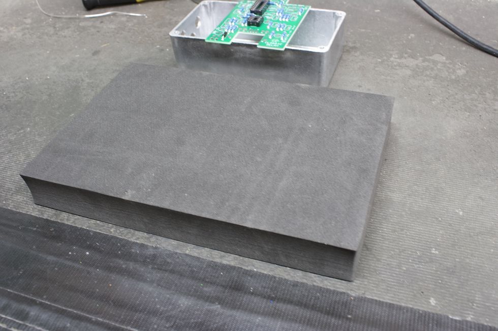
Photo 11
Place the 8-pin and 16-pin IC sockets into the corresponding pads on the top side of the PCB. We need to solder the IC socket pins from the bottom side. This means flipping the PCB over without having the IC sockets fall out. For this, I like to use a small piece of foam (Photo 11).
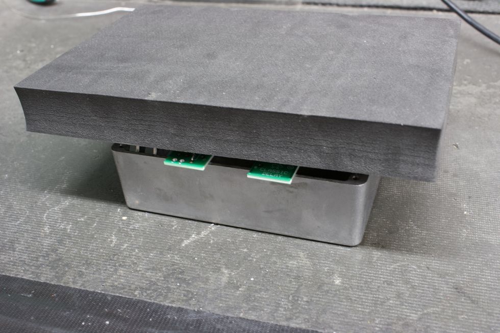
Photo 12
I place the foam on top of the PCB (Photo 12), then flip the foam and PCB simultaneously so the foam is below the PCB and the bottom side of the PCB is facing up (Photo 13).
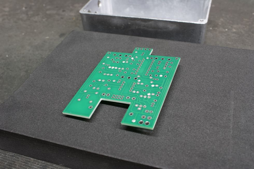
Photo 13
For this soldering step, we’ll want to solder ONLY 1 pad and then flip the board over to ensure that the IC sockets are sitting flush. If the IC sockets are not flush, go back to the bottom side and reflow that solder pad while pressing the PCB downward and keeping it parallel to the work surface. Solder the remaining pads (Photo 14).
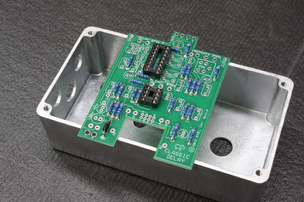
Photo 14
Step 7: Soldering the Voltage Regulator (page 12)
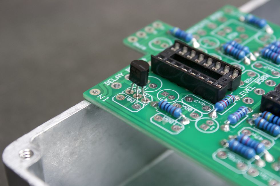
Photo 15
Place the voltage regulator into the three corresponding pads, while keeping mindful of the orientation. The flat side needs to match the outline on the PCB. Now, we’re ready to solder. This can be done from either side. Flush-cut the excess lead and we’re done here (Photo 15).
Step 8: Soldering the Trim Pot (page 13)
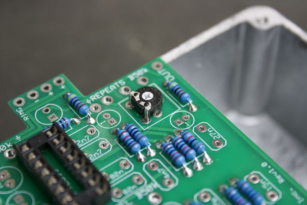
Photo 16
Place the trim pot (Photo 16) into its corresponding pads. For the trim pot provided, I found it easiest to solder the two exposed legs from the top side (Photo 17) and then the remaining leg from the bottom side.
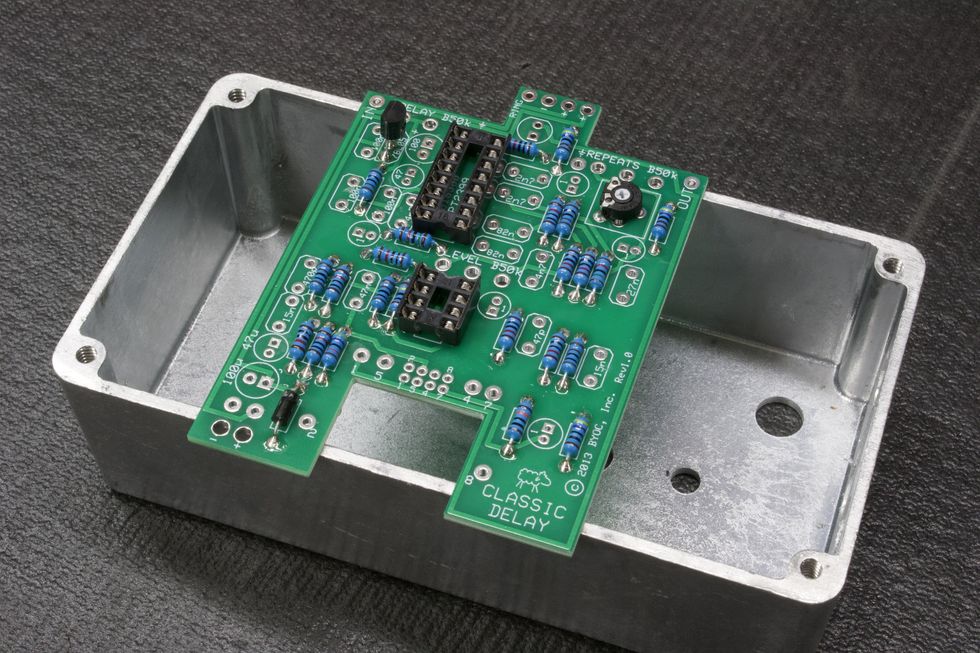
Photo 17
Step 9: Soldering Ceramic and Film Caps (page 14)
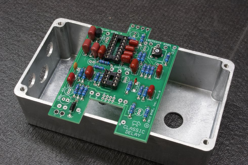
Photo 18
Place all ceramic (pill-shaped) and film (red) caps into their respective locations. Again, use page 7 of the instructions as a reference for identifying the correct capacitors (i.e. 100n film cap, which may say “104” or “.1” or “u1” on the body). We’ll need to solder the pads from the bottom side. So, once again, the piece-of-foam trick can be your friend here. Flush-cut the excess lead and we’re done (Photo 18).
Tip: An alternate method would be to bend the leads away from each other so they stay in place when the PCB is flipped over (Photo 19).
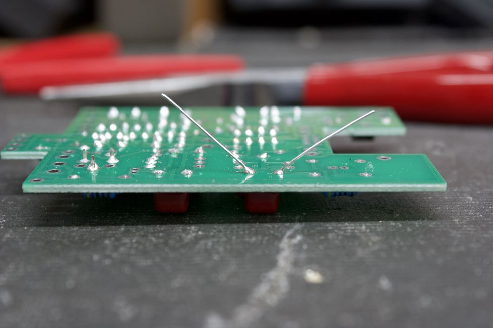
Photo 19
Step 10: Soldering Electrolytic Caps (page 15)
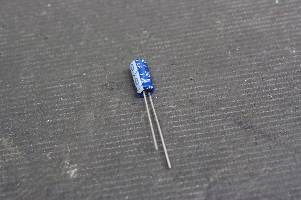
Photo 20
Let’s do the same thing here as we just did in Step 9. One thing to note is that electrolytic capacitors are polarized and need to be populated in the correct orientation. This is denoted on both the PCB and the component itself. On the PCB, the positive pad is denoted by the square pad. On the electrolytic capacitor, the positive lead is the longer leg. Additionally, the negative lead of the cap also corresponds to the white strip on the body (Photo 20).
So, let’s go ahead and populate the caps and solder them with either the foam trick or by bending the leads. Flush-cut the excess lead and we’re done (Photo 21).
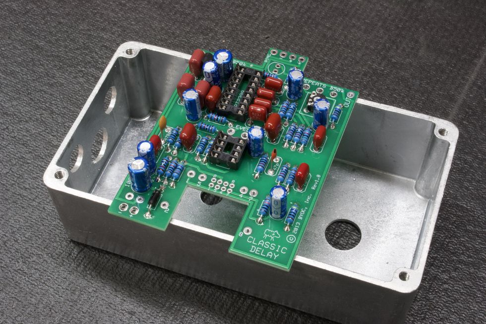
Photo 21
Step 11: Battery Snap and Hook-Up Wire
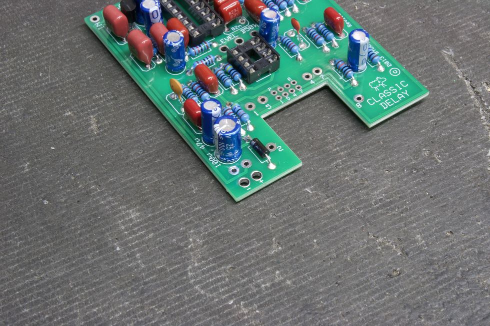
Photo 22
This DIY kit offers a battery option for those that feel so inclined. (See page 17 of the instructions.) For this step, we’ll need to connect the battery snap to the PCB. Before soldering, we’ll want to first feed the two wires through the holes directly below the solder pads. These holes act as strain relief for the battery snap and have + and - signs next to them (Photo 22). Then, simply solder the red wire to the positive (+) pad and the black wire to the negative (-) pad (Photo 23).
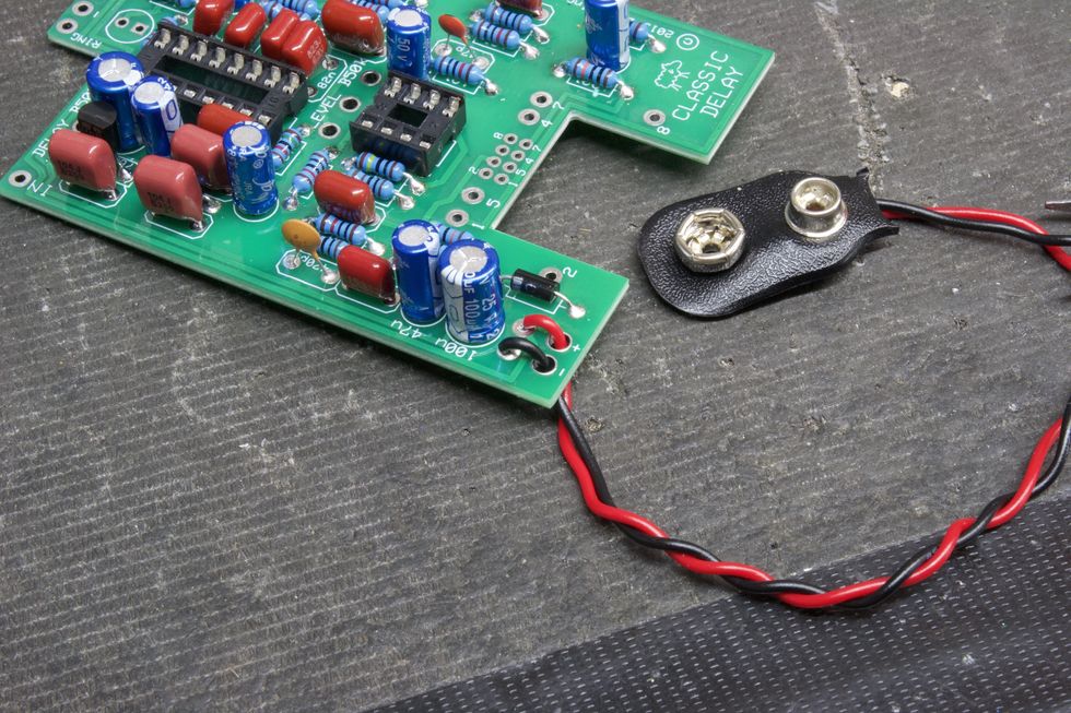
Photo 23
Next, we need to cut and strip the included wire (page 18). We need four 2.5" pieces of wire, and one 1.5" piece (Photo 24).
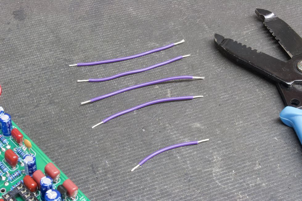
Photo 24
Place the 2.5" wires into the top side of the solder pads for in, out, and the two courtesy grounds—all handily marked. Then, solder from the bottom side. Do the same for the 1.5" wire going to the ring pad (Photo 25).
Tip: If painting the enclosure is desired, this is the last chance you’ll have to do it. After this, there will be components mounted to the chassis.
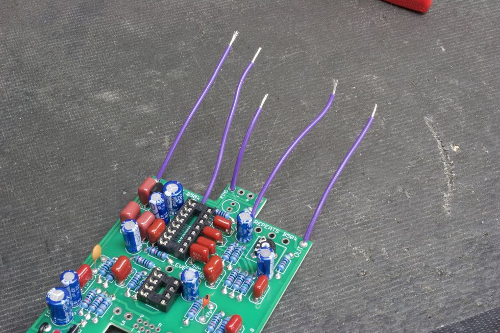
Photo 25
Step 12: Install DC Jack (page 19)
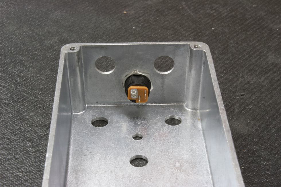
Photo 26
Place the DC jack into the large hole on the back heel of the enclosure and tighten the nut using a 14 mm (9/16") wrench (Photo 26).
Step 13: Potentiometers and Status LED (pages 20 and 21)
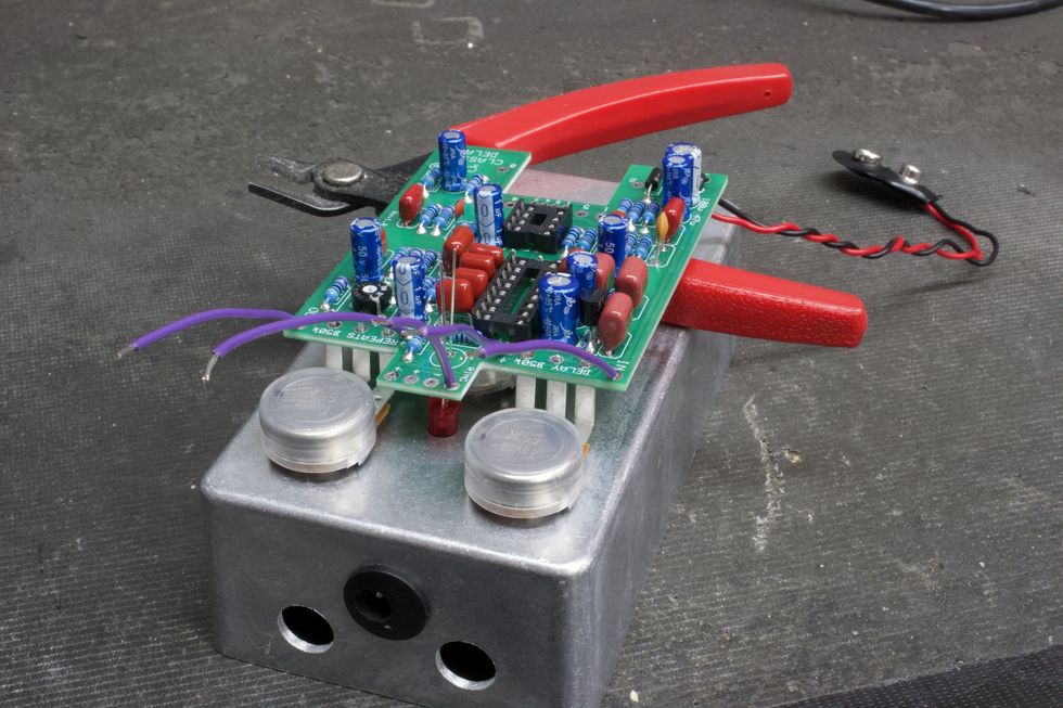
Photo 27
The included instructions for this next part have you mate the PCB to the inside of the enclosure. This will help line up the pots and LED. However, afterwards it will make soldering the remaining wire more difficult. Here’s a trick we can do that gives us the benefits of using the enclosure to help with pot alignment without needing to take the PCB out afterwards to solder the remaining wires. What we’ll want to do is simply use the face of the enclosure to hold the pots and set the LED height. Additionally, we can use the flush cutters to help balance the PCB (Photo 27). Be sure to have the long lead of the LED mate with the square pad, then solder away!
Step 14: Final Hook-Up Wire
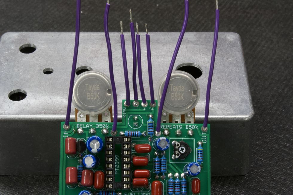
Photo 28
My steps continue to vary slightly from the instructions throughout the rest of the build, so you might want to do a side-by-side comparison. Let’s finish the wire for the DC jack next. Cut and strip three 1.5" pieces. These need to be placed into the three power pads at the top of the PCB marked -, +, + , as in Photo 28.
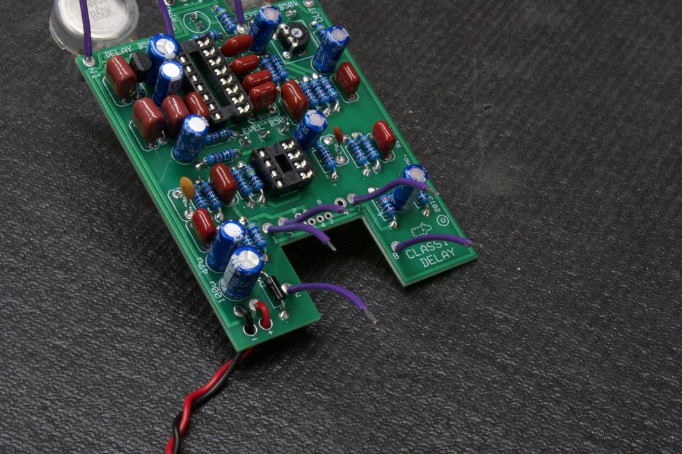
Photo 29
Next, cut and strip five more 1.5" pieces. Place these in the footswitch pads at the bottom of the PCB marked 1, 2, 5, 7, 8 as shown in Photo 29.
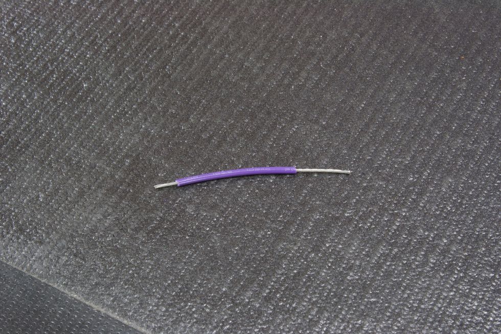
Photo 30
Last wire! Cut one 1.5" piece. Only for this one, strip half an inch off of one side (Photo 30). Place the short-stripped side into the footswitch pad labeled 4.
Step 15: Footswitch prep
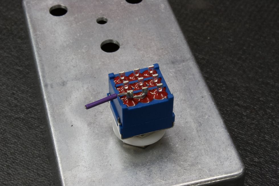
Photo 31
For the footswitch, we need to jump lugs 3 and 6. To do this, we’ll use the remaining wire. Place the footswitch into the correct hole on the face of the enclosure. Then, cut a 1" piece of wire and strip half of it. Feed the exposed wire through lug 3 and into lug 6 and then solder both (Photo 31). Cut the excess wire.
Step 16: Insert the IC
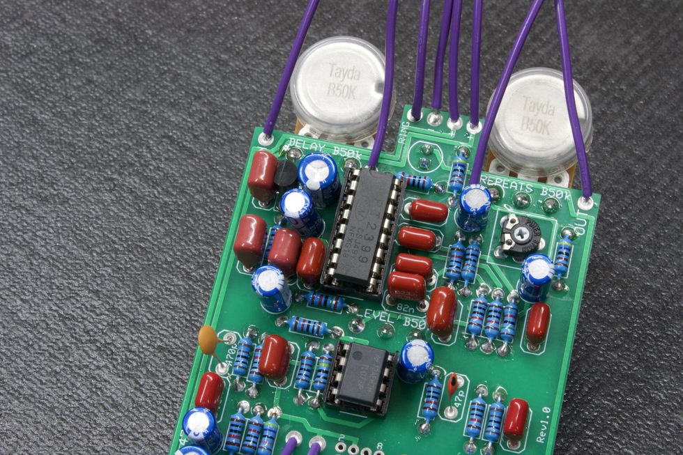
Photo 32
Now, we’re ready to insert the integrated circuits into their respective sockets. These need to be placed in the correct way, and there are two ways to identify them. Pin 1 is the top left leg of the IC—which is the rectangular black object in Photo 32. These legs are marked with a small dot in the top left corner or the upside of the IC is marked with a debossed half circle.
Step 17: Mounting and Final Soldering
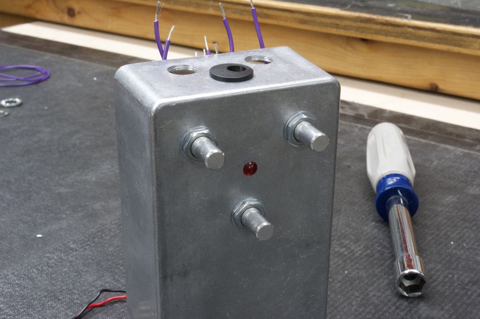
Photo 33
PCB: Now for the real fun! We’re ready to start inserting chassis-mounted components. Let’s start with the populated PCB. Place the PCB with the three pots lining up with the drilled holes, place the pot washers on the shafts, and then tighten the pot nuts using a 10 mm (25/64") nut driver/wrench, for the results in Photo 33.
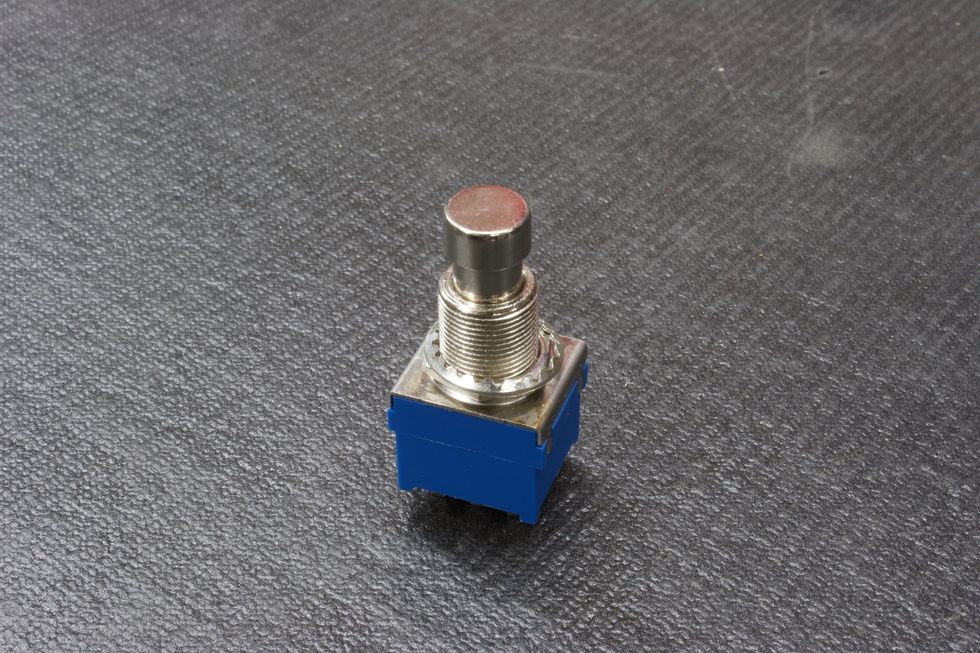
Photo 34
Footswitch: Now that the PCB is securely tightened, let’s go ahead and do the same for the footswitch. Remove all hardware from the footswitch bushing except for one nut and the lock washer (Photo 34).
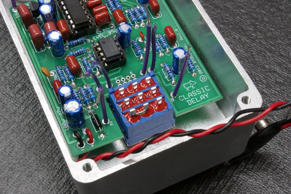
Photo 35
Feed the footswitch through the footswitch hole, making sure that the footswitch has the two poles that we soldered together facing the bottom left (Photo 35).
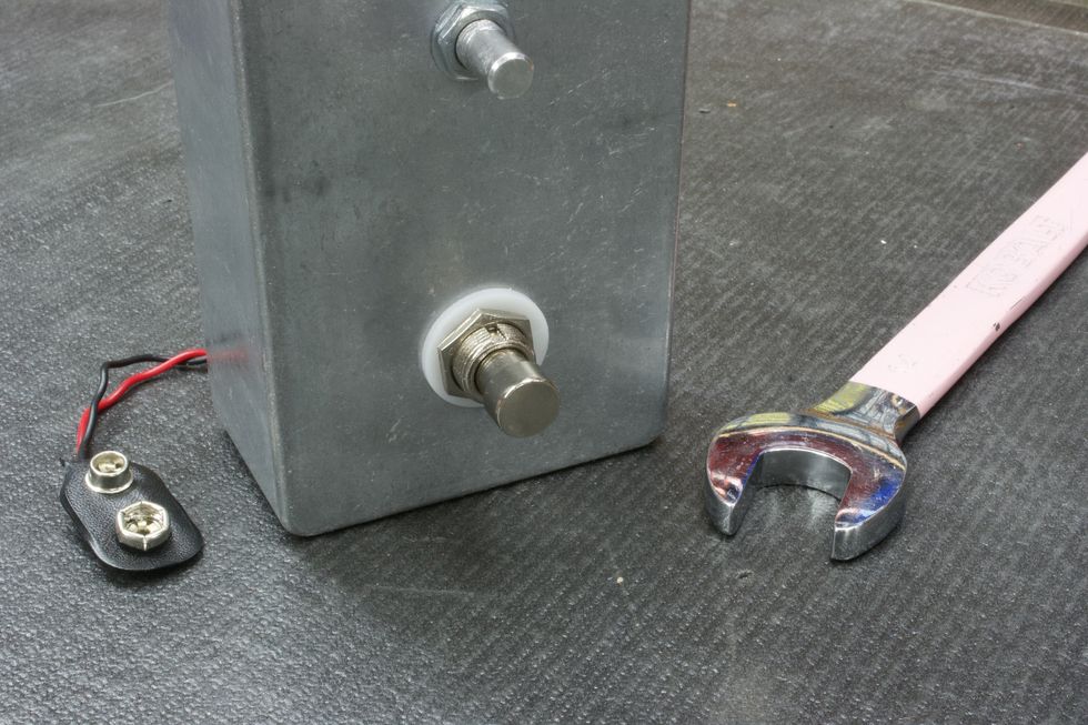
Photo 36
Next, place the plastic washer onto the bushing (optional), and tighten the hex nut with a 14 mm (9/16") wrench (Photo 36).
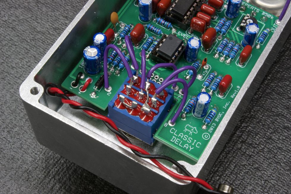
Photo 37
Lets go ahead and solder the footswitch wires to their respective footswitch poles (Photo 37). See the instructions’ page 26 for pole-numbering reference.
Tip: Solder from the top row down—i.e. 1, 4, 7, then 2, 5, 8.
Another tip: Remember that the wire for pole 4 also connects to pole 9.Step 18: DC Jack
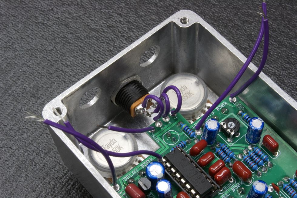
Photo 38
Next, we’ll need to solder the three wires that go to the DC jack, as explained in page 22 of the instructions. Start with the middle wire, since it sits the lowest and will be easier to get at without the other two wires in the way (Photo 38).
Step 19: Audio Jacks
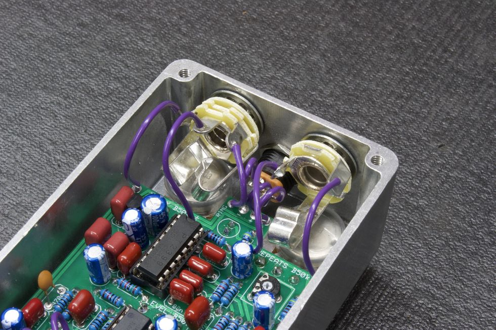
Photo 39
The last chassis-mounted components are the two audio jacks. Let’s do the stereo input jack first. Go to page 24 of the instructions to see how these jacks are oriented. The lock washer goes on the bushing first, then gets placed into the hole to the left of the DC jack. Then, place the washer onto the bushing and tighten the hex nut with a 1/2" nut driver/wrench.
Follow the same steps for the mono output jack. And then, it’s the final soldering step: Solder the wires to the appropriate lugs on the audio jacks (Photo 39), as on instructions page 28. Then, finally, place the knobs on, tighten them down, and we’re done!
- The DIY Relic Job—Fantasy or Reality? ›
- DIY - Premier Guitar ›
- DIY Pedalboard Build ›
- Reader Guitar of the Month: Strat Style ›
- Are You Throwing Away Money Cleaning Your Shop? - Premier Guitar ›
Fender introduces the Stories Collection Mike Campbell Red Dog Telecaster, paying tribute to the iconic guitarist's heavily modified instrument. Featuring two signature humbuckers, a custom single coil bridge pickup, Bigsby tremolo, and a unique "Destruct" circuit, this Telecaster allows players to channel Campbell's legendary tone and style.
Today, Fender Musical Instruments Corporation (FMIC) and the Fender Custom Shop (FCS) introduce the newest member of the ‘Stories Collection’ family—a series of instruments that pays tribute to iconic Fender guitars and basses that have been uniquely modified by the legendary artists who played them. Mike Campbell, the tasteful and versatile player who is responsible for some of Tom Petty and the Heartbreakers’ most memorable riffs, has teamed up with Fender and the Custom Shop to develop the Stories Collection Mike Campbell signature guitars - the Red Dog Telecaster and FCS Limited Edition Masterbuilt 1972 “Red Dog“ Telecaster—two reproductions of Campbell’s stunning and heavily modified Telecaster that gives players the opportunity to create their own sonic identity through the framework of one of rock and pop’s greatest guitar players.
“Telecasters are the heart and soul of rock and roll music and this one is a beautiful instrument,” said Mike Campbell. “I could tell The Red Dog was special as soon as I picked it up. It felt like it was in the right place at just the right time. The humbuckers give it so much power and such a wide variety of tones while the destruct button really sets it apart from just about any other tele.”
The tale of the Red Dog Telecaster began when one of Campbell’s former students living in Florida offered to sell him a guitar. However, after seeing the guitar in question, it became clear that this was no standard instrument pulled from the rack. Campbell was presented with a bright red Tele equipped with humbuckers in the neck and middle position, a Bigsby tremolo and, perhaps the guitar’s most idiosyncratic flourish, an onboard electronic boost dubbed the “destruct” circuit. As any other lifelong guitar devotee would, Campbell bought this glorious Frankenstein of an instrument without a moment’s hesitation. The Red Dog was subsequently used most memorably on the Heartbreaker’s track “Refugee” and is prominently featured in the song’s music video. All throughout his storied career playing with Tom Petty, as a session guitarist, alongside Fleetwood Mac and touring the world with his solo act The Dirty Knobs, this singular Telecaster has been inextricably linked to Campbell’s career and legacy as one of rock and roll’s finest players.
The Stories Collection Mike Campbell Red Dog Telecaster offers the same level of craftsmanship and sonic capability at a more accessible price point. The two signature Mike Campbell humbuckers in the neck and middle position bring a low-end growl and high octane output that sets it apart from other Telecaster guitars. However, the custom single coil bridge pickup delivers the caliber of twang that people worldwide associate exclusively with Tele guitars. A Bigsby B5F tremolo allows players to extenuate riffs and solos with an additional level of flourish and attitude. Perhaps the Red Dog’s most exciting feature lies beneath the surface—the “Destruct” circuit. With the push of a sleek silver button on the control plate, an added 34 dB of gain can be activated for complete tonal dominance.
“It’s our mission to honor the legacy and sonic character that Mike Campbell has infused into every note played on his beloved ‘Red Dog’ Telecaster®,” said Justin Norvell, Executive Vice President of Fender Products. “Every scratch, modification, and battle scar tells a story, and with these meticulously crafted recreations, we’re giving players everywhere the chance to channel that same timeless energy and write their own musical history.”
While the Red Dog Telecaster came into his hands already modified, its custom features were universal and powerful enough to elevate Campbell’s personal playing style and the same can be said for Fender’s painstakingly detailed and powerfully crafted recreations. The FCS Limited Edition Masterbuilt 1972 “Red Dog” Telecaster is a jaw dropping representation of the instrument as it exists today—dings, paint chips, dents and all by FCS’s Senior Masterbuilder Dennis Galuska. Outfitted with vintage replica Arcane, Inc. pickups and signature “Destruct” boost circuit wired by Analogman, this custom Telecaster can achieve the same biting jangle heard on “Refugee.” Features include a flat sawn maple neck with custom Oval “C” back shape, 7.25” radius fingerboard, 21 vintage upgrade frets, 5-way pickup sector and vintage style Jazzmaster bridge with threaded saddles.
“The ‘Red Dog’ Telecaster® is a testament to how a heavily modified instrument can be both deeply personal and universally cherished,” said Chase Paul, Director of Product Development - Fender Custom Shop. “There’s an undeniable magic in an instrument that evolves alongside its player, and every modification on this guitar serves a purpose, working together to create something greater than the sum of its parts. Dennis Galuszka and the Custom Shop dedicated countless hours to faithfully recreating every detail, bringing players and fans as close to Mike’s legendary Tele® as possible.”
Stories Collection Mike Campbell Red Dog Telecaster® ($3,499.99) Revered for his tasty rhythms and fiery leads, Mike Campbell is responsible for many of the iconic hooks from the Tom Petty and the Heartbreakers catalog. For decades now his faithful Fender guitars have been at the heart of his trusted formula for award-winning tone.Campbell bought what became known as the “Red Dog” from a former guitar student in Florida, complete with Bigsby tremolo and a powerful onboard boost, known as the “Destruct” circuit. Mike’s iconic 1972 Red Dog Telecaster is featured on the Damn the Torpedoes track “Refugee” and can be seen in the accompanying music video. The Stories Collection Mike Campbell “Red Dog” Telecaster features an Heirloom™ nitrocellulose lacquer “Red Dog Red” finish, 1-piece maple neck with 7.25” radius fingerboard and 21 vintage-style frets as well as an onboard “Destruct” boost circuit. The custom Mike Campbell Red Dog pickup set features two vintage-style humbuckers and a single-coil Telecaster bridge pickup, Bigsby B5F tremolo and a custom Red Dog neck plate. Custom accessories include a vintage-style case, strap, picks and certificate of authenticity.
Unique, versatile and utterly original, The Mike Campbell “Red Dog” Telecaster pays tribute to a veteran Heartbreaker with a serious knack for writing extraordinary songs and delivering catchy, captivating and magnificent guitar parts.
Fender Custom Shop Limited Edition Masterbuilt Mike Campbell 1972 “Red Dog” Telecaster® ($20,000.00) With raw, powerful riffs and explosive leads, Mike Campbell firmly established himself as one of the greatest guitarists and songwriters in music history—and throughout his accomplished career, Fender guitars played in integral role in his creative expression. One of his most noteworthy instruments was his modified three-pickup Telecaster that would come to be known as the “Red Dog.” Fender Custom Shop Senior Masterbuilder Dennis Galuszka partnered with Mike to recreate this incredible guitar. From beautifully faded red metallic finish to the worn and Bigsby B5 vibrato tailpiece, every nick, ding and scratch was meticulously replicated to bring this tribute guitar to life. Loaded with vintage replica Arcane, Inc. pickups and a “Destruct” boost circuit wired by Analogman, this Tele plays, sounds and feels just like the guitar heard on “Refugee.” Its two-piece select alder body and custom-shaped, one-piece maple neck feature a well-loved Relic® lacquer finish, while the hardware is aged to look like it’s been played for the last five decades. Wonderfully unique and with a storied past, the Limited Edition Masterbuilt Mike Campbell 1972 “Red Dog” Telecaster is a fitting homage to such an incredibly captivating and inspiring musician. Other premium features include flat sawn maple neck with custom Oval “C” back-shape, 7.25” (184.1 mm) radius, 21 vintage upgrade (45085) frets, 5-way switch, 3-ply parchment pickguard, vintage-style Jazzmaster® bridge with threaded steel saddles, vintage-style “F”-stamped tuning machines, bone nut, two American Vintage ‘65+ string trees with nylon spacers, deluxe hardshell case, strap and certificate of authenticity.
For more information, please visit fender.com.
Fender Stories Collection Mike Campbell Red Dog Telecaster Electric Guitar - Red Dog Red
Stories Collection Mike Campbell Red Dog Tele, MapExpansive range of subtle thickening and focusing tones to fuzz. Great alternative to run-of-the-mill overdrive and fuzz. Enables surgical shaping of guitar sounds within a mix.
Interactive, sometimes sensitive controls make certain tones elusive and lend the pedal a twitchy feel.
$179
Catalinbread Airstrip
With the preamp from a Trident A-Range console as their target, Catalinbread conjures up a varied gain device that can massage or mangle your guitar tone.
Replicating a recording console preamp in a pedal is a pretty elementary idea, but it’s inspired stompboxes as varied as theJHS Colour Box andHudson Broadcast. All recording desks—and the pedals that imitate them—have their own color. Catalinbread’s Airstrip chases the sound of a Trident A-Range channel strip. (Search “Trident Studios” to get a handle on the kind of clientele the place attracted back in the ’60s and ’70s).
Presently, a new Trident A-Range channel strip costs thousands of dollars. An original? Well, only 13 desks were made, so you can probably get a nice used Rolls Royce for less—if you can find one. Rightly then, one should temper expectations about how well a $179 pedal can ape a priceless console. But like many preamps in a box, the Airstrip excels at a wide range of gain-shaping tasks, from surgical boost and EQ shadings to fuzzy, filtered, ready-to-rip-through-a-mix Jimmy Page/Beatles/Neil Young-style direct-to-desk tones. Even at extremes, the Airstrip is sensitive to touch, volume, and tone dynamics, enabling pivots from light (if very focused) overdrive to ’60s germanium-fuzz-like sounds with changes in guitar volume and tone. And though it’s dynamic and responsive, at many settings it also exhibits lovely compression tendencies, softening transients before giving way to wide-vista tone blooms—a great recipe for spare, lyrical, melodic leads with a ’60s biker-flick-soundtrack edge. Without any of its market-leading competitors around for comparison, it’s hard to say exactly how the Airstrip aligns with their EQ biases and core tones. What is certain is that there are scores of mellow to unconventionally aggressive colors here to explore.
AI, which generated this image in seconds, can obviously do amazing things. But can it actually replace human creativity?
Technology has always disrupted the music biz, but we’ve never seen anything like this.
AI has me deeply thinking: Is guitar (or any instrument) still valid? Are musicians still valid? I don’t think the answer is as obvious as I’d like it to be.
As a professional musician, I’ve spent the vast majority of my days immersed in the tones of tube amps, the resistance of steel strings under my fingers, and the endless pursuit of musical expression. Each day, I strive to tap into the Source, channel something new into the world (however small), and share it. Yet, lately, a new presence has entered the room—artificial intelligence. It is an interloper unlike any I’ve ever encountered. If you’re thinking that AI is something off in the “not-too-distant future,” you’re exponentially wrong. So, this month I’m going to ask that we sit and meditate on this technology, and hopefully gain some insight into how we are just beginning to use it.
AI: Friend or Foe?
In the last 12 months, I’ve heard quite a bit of AI-generated music. Algorithms can now “compose,” “perform” (with vocals of your choosing), and “produce” entire songs in minutes, with prompts as flippant as, “Write a song about__in the style of__.” AI never misses a note and can mimic the finer details of almost any genre with unnerving precision. For those who are merely curious about music, or those easily distracted by novelty, this might seem exciting … a shortcut to creating “professional” sounding music without years of practice. But for those of us who are deeply passionate about music, it raises some profound existential questions.
When you play an instrument, you engage in something deeply human. Each musician carries their life experiences into their playing. The pain of heartbreak, the joy of new beginnings, or the struggle to find a voice in an increasingly noisy and artificial online world dominated by algorithms. Sweat, tears, and callouses develop from your efforts and repetition. Your mistakes can lead to new creative vistas and shape the evolution of your style.
Emotions shape the music we create. While an algorithm can only infer and assign a “value” to the vast variety of our experience, it is ruthlessly proficient at analyzing and recording the entire corpus of human existence, and further, cataloging every known human behavioral action and response in mere fractions of a second.
Pardon the Disruption
Technology has always disrupted the music industry. The invention of musical notation provided unprecedented access to compositions. The advent of records allowed performances of music to be captured and shared. When radio brought music into every home, there was fear that no one would buy records. Television added visual spectacle, sparking fears that it would kill live performance. MIDI revolutionized music production but raised concerns about replacing human players. The internet, paired with the MP3 format, democratized music distribution, shattered traditional revenue models, and shifted power from labels to artists. Each of these innovations was met with resistance and uncertainty, but ultimately, they expanded the ways music could be created, shared, and experienced.
Every revolution in art and technology forces us to rediscover what is uniquely human about creativity. To me, though, this is different. AI isn’t a tool that requires a significant amount of human input in order to work. It’s already analyzed the minutia of all of humanity’s greatest creations—from the most esoteric to the ubiquitous, and it is wholly capable of creating entire works of art that are as commercially competitive as anything you’ve ever heard. This will force us to recalibrate our definition of art and push us to dig deeper into our personal truths.
“In an age where performed perfection is casually synthesized into existence, does our human expression still hold value? Especially if the average listener can’t tell the difference?”
Advantage: Humans
What if we don’t want to, though? In an age where performed perfection is casually synthesized into existence, does our human expression still hold value? Especially if the average listener can’t tell the difference?
Of course, the answer is still emphatically “Yes!” But caveat emptor. I believe that the value of the tool depends entirely on the way in which it is used—and this one in particular is a very, very powerful tool. We all need to read the manual and handle with care.
AI cannot replicate the experience of creating music in the moment. It cannot capture the energy of a living room jam session with friends or the adrenaline of playing a less-than-perfect set in front of a crowd who cheers because they feel your passion. It cannot replace the personal journey you take each time you push through frustration to master a riff that once seemed impossible. So, my fellow musicians, I say this: Your music is valid. Your guitar is valid. What you create with your hands and heart will always stand apart from what an algorithm can generate.
Our audience, on the other hand, is quite a different matter. And that’s the subject for next month’s Dojo. Until then, namaste.
Genuine, dynamic Vox sound and feel. Plenty of different tone-sweetening applications. Receives other pedals as nicely as a real amp.
Can get icy quick. Preamp tube presents risk for damage.
$299
Tubesteader Roy
tubesteader.com
The Roy is an exceedingly faithful Vox box that brings genuine tube dynamics to your pedalboard.
This is an interesting moment for amp-in-a-box pedals. It used to be novel to have a little box that approximated the tone signature of an iconic amp. Nowadays, though, modeling pedals and profilers can give you many digital emulations in one package. Nevertheless, there are still worlds of possibility in pedals that copy amp topology in discrete form—particularly when you add a real preamp tube to that mix.
That’s what Montreal builder Tubesteader did with the Roy, their entry in the Vox-Top-Boost-AC30-in-a-box race. The Roy is a 2-channel preamp and overdrive built around a 12AX7 vacuum tube—a design gambit that is relatively uncommon if not totally unique. The tube makes the Roy look much more vintage in spirit at a time when sleek, black Helixes and Fractals are overtaking stages. In some ways, it looks like an antique. It can sound like one in the best way too.
Riding the Tube
The Roy comes in a handsome brownish-red enclosure, with an unsurprising control layout. The rightmost footswitch turns the pedal on and off, and the one at left switches between the identical channels. Each channel has an output volume and gain knob; the controls on the right are assigned to the default channel, and when you tap the left footswitch, you engage the left-side control tandem. The treble and bass controls between the two volume and gain knobs are shared by the two channels, but a post-EQ master tone cut control, which rolls off additional treble frequencies, is mounted on the crown of the pedal beside the power input. The input and output jacks occupy the left and right sides, along with a 3.5 mm jack for external operation. The Roy runs at 12 volts and draws 350 mA, and the included power supply can be reconfigured easily for a range of international outlets.
Tubesteader’s literature says the pedal’s tones are generated via a high-voltage transistor in the first gain stage coupled with the 12AX7, which operates at 260 volts. That preamp tube is nested at the top of the enclosure’s face, underneath a protective metal “roll bar”. Trusty as it looks, when there is a glass element on the exterior of a pedal’s housing, there’s an element of vulnerability, and transporting and using the Roy probably requires a more conscientious approach than a standard stompbox.
Royal Tones
Compared to the Vox's own Mystic Edge, an AC30-in-a-box from Vox powered by Korg’s NuTube vacuum fluorescent display technology, the Roy feels warmer, and more dynamic, proving that the 12AX7 isn’t just there for looks. The Mystic Edge could sound positively icy compared to the Roy’s smooth, even breakup. The Roy is very happy at aggressive settings, and in my estimation, it sounds best with output volumes driving an amp hard and the pedal’s gain around 3 o’clock. That recipe sounds good with single-coil guitars, but with a P-90-loaded Les Paul Junior, it achieves roaring classic-rock greatness. I’ve always felt Voxes, rather than Marshalls, are better vehicles for dirty punk chording. The Roy did nothing to dissuade me from that belief. And the pedals' midrange punch and bark in power-chord contexts lent authority and balance that makes such chords hit extra hard.
Though the Roy creates many of its own tasty drive tones, it really comes to life when pushed by a boost or overdrive, much like a real amp. When I punched it with a Fish Circuits Model One overdrive, the Roy was smoother and less spiky than a cranked AC30, yet there was plenty of note definition, attack, and the harmonic riches you’d turn to an AC for in the first place. A JFET SuperCool Caffeine Boost also brought additional depth and color to the output and broadened the pedal’s voice.
If you’re most comfortable with a real Vox amp, the Roy is a reliable and familiar-feeling stand-in when managing a different backline amp. In at least one way, though, the Roy is, perhaps, a bit toofaithful to its influence’s design: There’s a lot of treble on tap, and it’s easy to cook up tinnitus-inducing frequencies if you get too aggressive with the treble control. Noon positions on the cut/boost tone knobs sound pretty neutral. But I found it difficult to push the treble much past 2 o’clock without wincing—even with the tone cut control set at its darkest. (This quality, of course, may make the Roy a good match for squishier Fender-style designs). The relationship between the Roy’s treble and bass controls also takes time to master. The two don’t just add or boost their respective frequencies, but also add or subtract midrange, which can result in intense and sudden gain-response changes. As a general guideline, a light touch goes a long way when fine tuning these frequencies.The Verdict
The Roy isn’t exactly a bargain at $299. Then again, this Vox-in-a-box can stand in for real-deal Top Boost tones and the 2-channel design means you can move between an AC’s chimey cleans and ripping cranked sounds in a flash. If you’re squarely in the Vox amp camp, you’d be hard-pressed to find a more authentic means of achieving that range of clean-to-crunchy sounds.