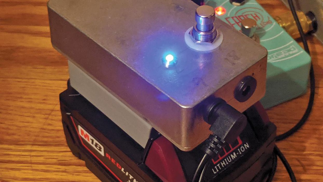
The finished BYOC Classic Delay kit (Photo 1).
Never kit-built a stompbox? It’s easy—if you let pro pedal maker Alex Guaraldi of CopperSound be your guide. Here, he takes you on a step-by-step tour as he assembles a Build Your Own Clone Classic Delay.
For this DIY adventure, we’re going to be walking through the steps of building the Classic Delay pedal from Build Your Own Clone (BYOC), a company that has been a big player in the pedal-kit game for quite a while. This is a little more complicated than building a fuzz or overdrive, so I’m going to explain the process with great detail. Let’s get started.
Tools You’ll Need for This Project
- Soldering Iron
- Solder
- #2 Phillips screwdriver
- Wire strippers
- 8 mm (5/16") nut driver/wrench
- 10 mm (25/64") nut driver/wrench
- 1/2" nut driver/wrench
- 14 mm (9/16") wrench
- Flush cutters
- Small needle-nosed pliers
- Third hands
These tools are available via a variety of suppliers, including StewMac, Allparts, and Amazon.
Step 1: Review the Instructions
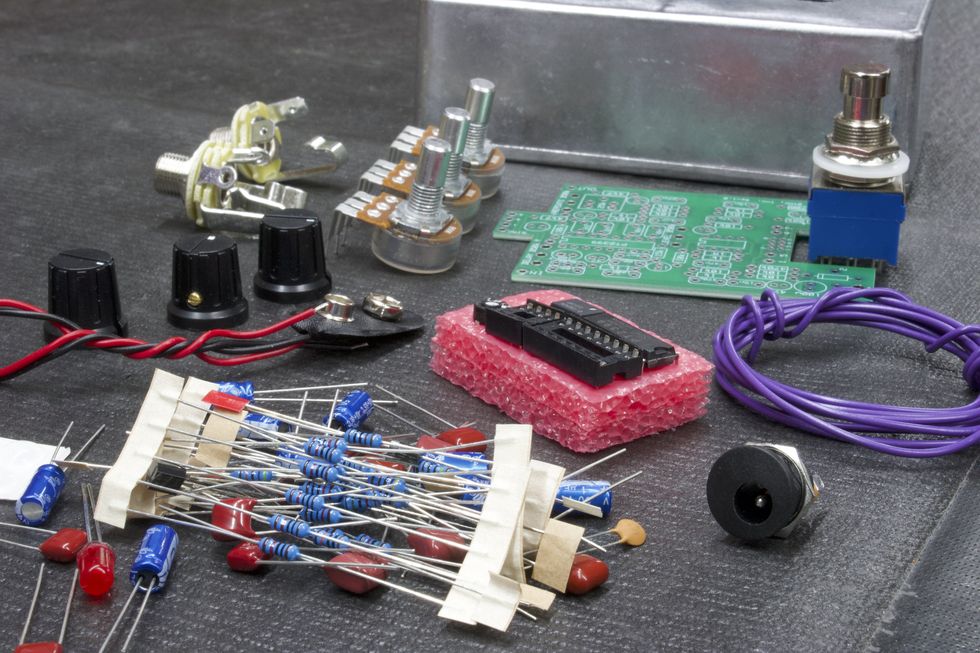
The kit as it arrives (Photo 2).
Each BYOC kit comes with a detailed set of instructions in the form of a PDF that can easily be printed out. The Classic Delay’s instructions can be found at https://www.byocelectronics.com/classicdelayinstructions.pdf. They are 32 pages long, and I suggest following their steps as you read this article. Here, I will refer to specific page numbers that correspond with the steps. I’ve also taken photos to coincide with the steps. Within the instructions, we find a table of contents, pictures of the fully assembled pedal, a list of parts included, and step-by-step instructions from internal population and soldering to external assembly. With any kit, always read the instructions carefully before you start building.
Step 2: PCB set-up
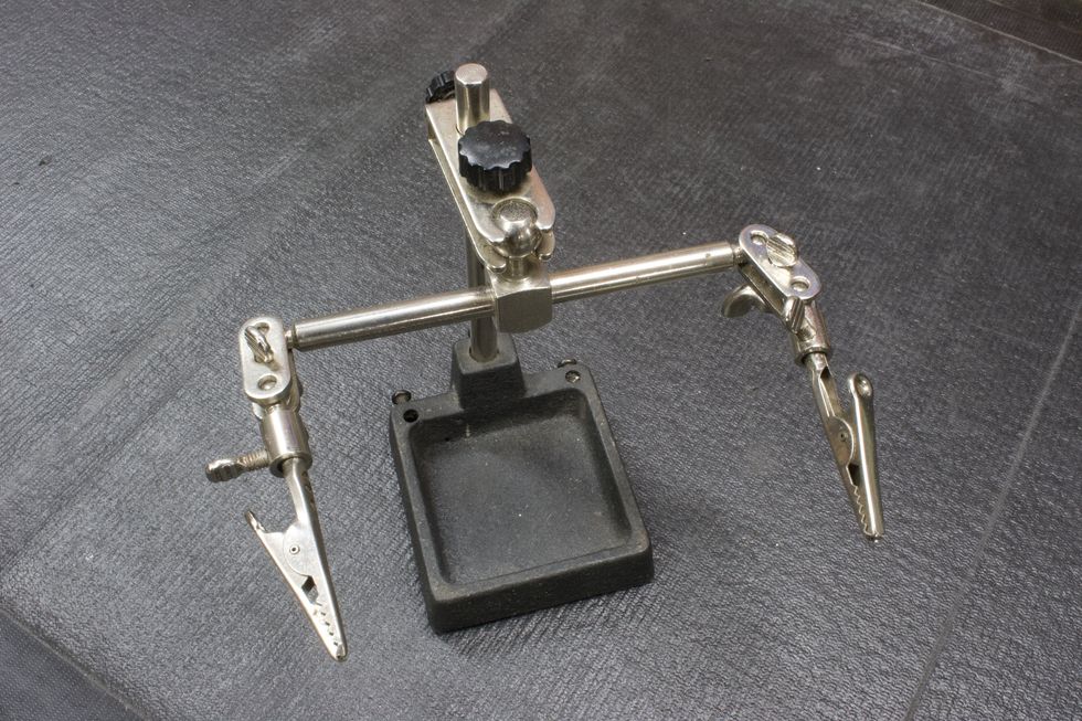
Photo 3
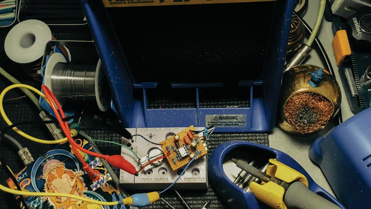
A lot of pedal builders use PCB jigs that are specifically designed to hold several printed circuit boards so that they can be easily populated and soldered. These jigs are great tools. However, they’re not something a casual DIY enthusiast will often have. Essentially, all we really need to do is elevate the PCB off of the working surface so that the leads of the components can pass through the bottom side of the PCB. This is most helpful with components that can be soldered from the top side of the PCB. “Third hands” or “helping hands” (Photo 3) are a good tool for this job. So, what can we do to elevate the PCB if we don’t have access to third hands? Simply turn the enclosure upside down and place the PCB perpendicular (Photo 4). This will elevate the PCB enough to allow the component leads to easily pass through.
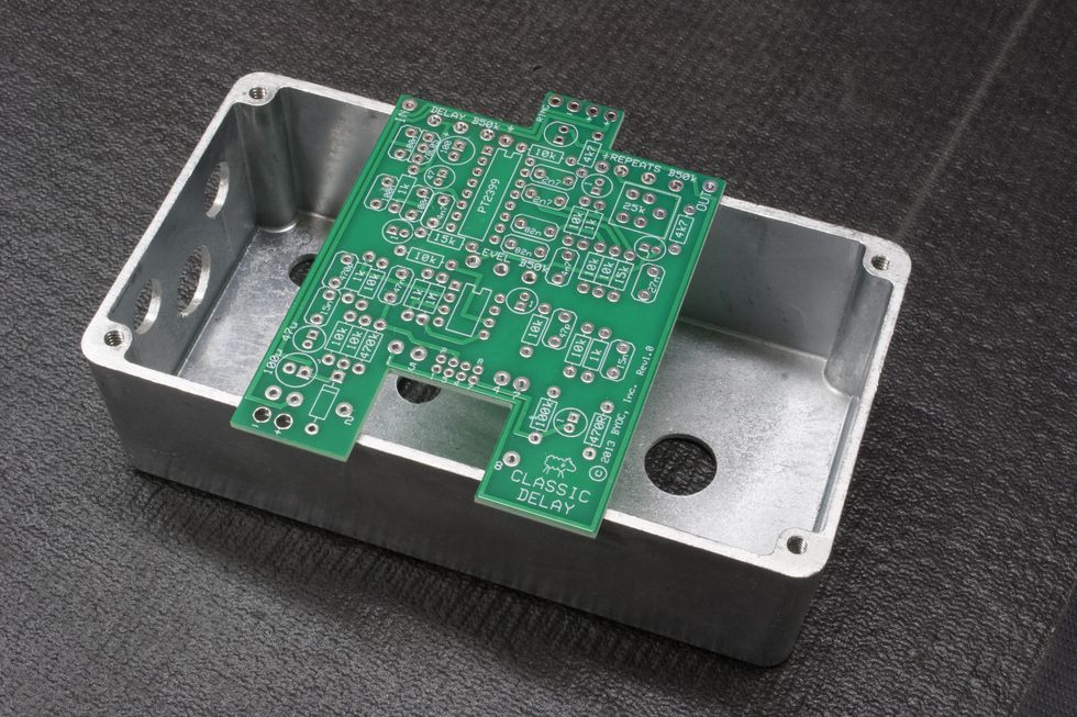
Photo 4
Step 3: Populating Resistors and Diodes (instructions page 9)
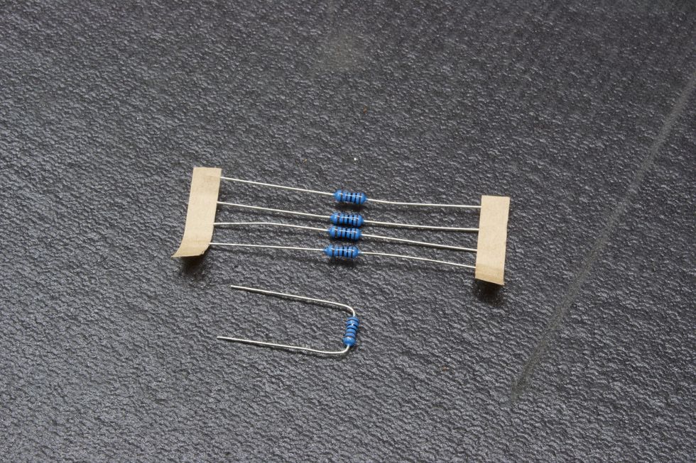
Photo 5
When populating PC boards, we typically like to work lowest to tallest in regards to the seating. Seating is how far above the PC board the component rests. Resistors and diodes sit pretty low to the PC board, so populating them first makes sense.
Resistors: Remove the resistor from the paper ribbon, bend the leads (Photo 5), and place them through the corresponding pads (Photo 6) as directed. (A pad, by the way, is the term for the designated surface area of a component’s electric contact point.) A good practice is to populate all resistors of the same value before moving on to the next value. Populate all 1k resistors, then all 10k resistors, and so on.Photo 6
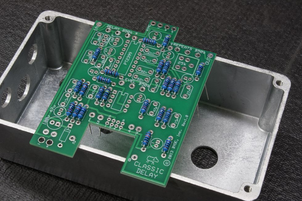
Reading resistor color bands can be confusing, so don’t forget the reference guide on page 7 of the instructions. Here, you will find a detailed breakdown of each value and its corresponding 5-band reading (i.e. 1k = brown/black/black/brown/brown). Once all the resistors are placed, we can go on to the diode.
Diode: Next, we need to place the diode. Just like resistors, remove the diode from the paper ribbon, bend the leads, and place them through the corresponding pads. Diodes are polarized and need to be oriented a certain way (Photo 7). Be sure to match the diode to the outline on the PCB, as shown on page 10 of the instructions.
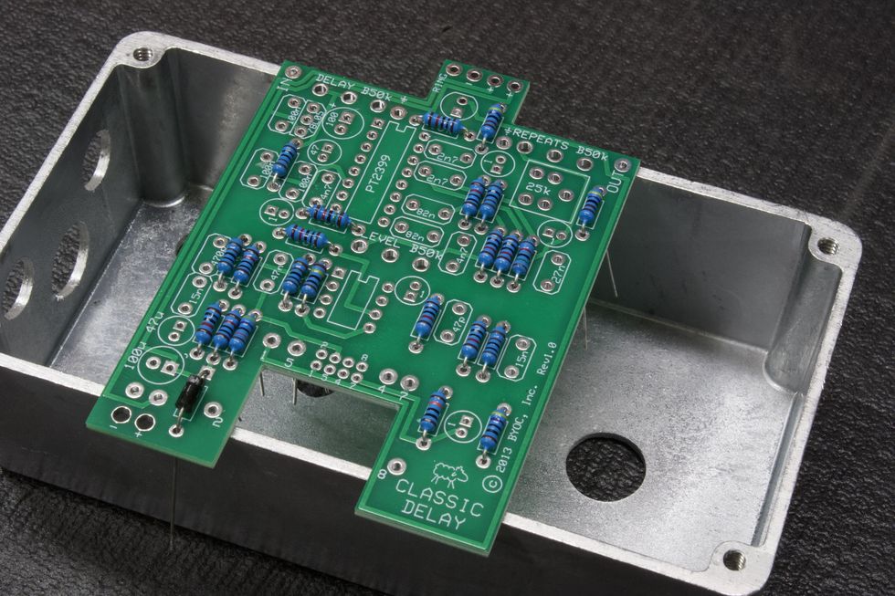
Photo 7
Step 4: Solder Resistors and Diode
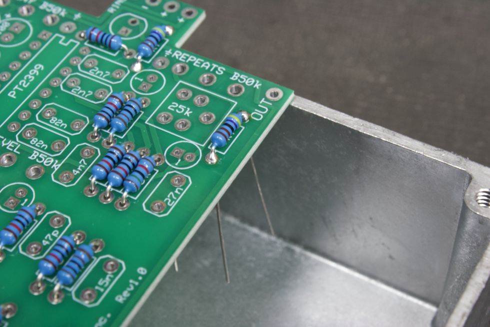
Photo 8
Fire up the soldering iron! Once the iron is up to temperature (650 to 750 degrees Fahrenheit, depending on how fast you work), it’s time to get to work. Resistors and diodes can easily be soldered from the top side. So no need to flip the PCB over. Place the solder tip to the pad and feed the end of the tip a bit of solder. What we’re looking for here is solder that covers the entire pad, encapsulates the lead, and has a nice shine to it. Think of it like a shiny Hershey's Kiss shape (Photo 8). Repeat this step for every part. If you’re new to soldering, you should consult our concise guide to soldering, online or in PG’s October 2015 issue.
Soldering tip: Shut the iron off between population steps. Use a small, tabletop fan to blow the solder fumes away during soldering steps. Quick tutorial videos on YouTube are also of benefit here, for builders new to soldering.
Step 5: Trim the Leads
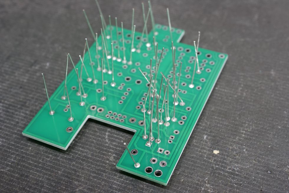
Photo 9
Next, place the PCB upside down to expose the leads (Photo 9). Using flush cutters, trim the excess leads (Photo 10).
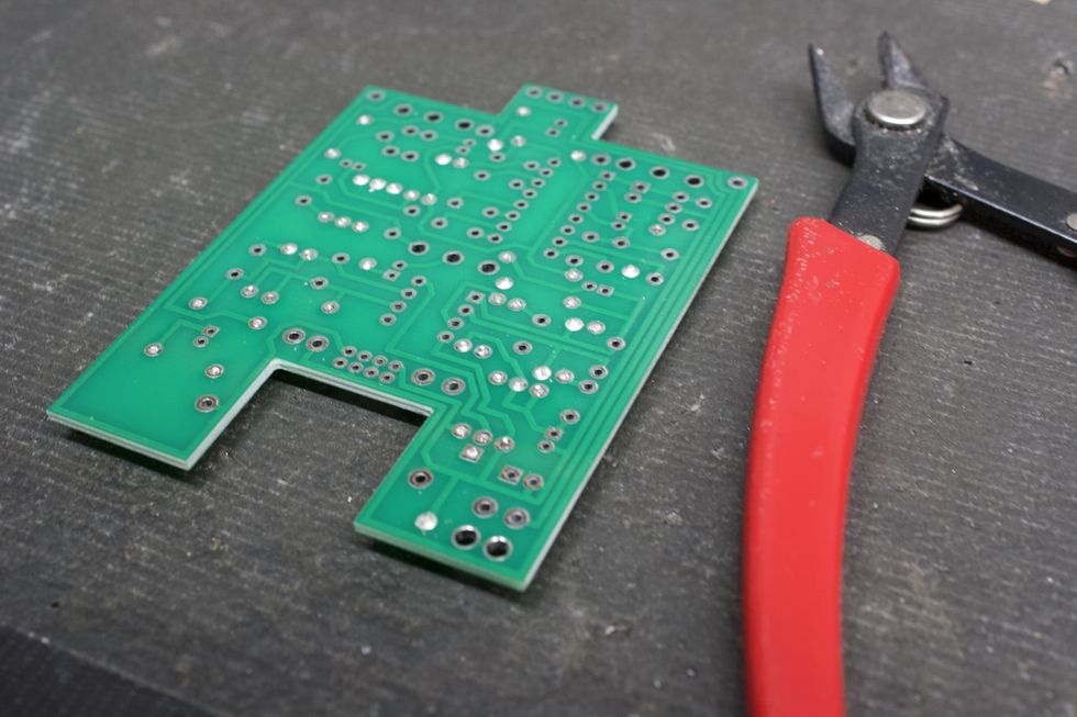
Photo 10
Step 6: Soldering IC Sockets (page 11)
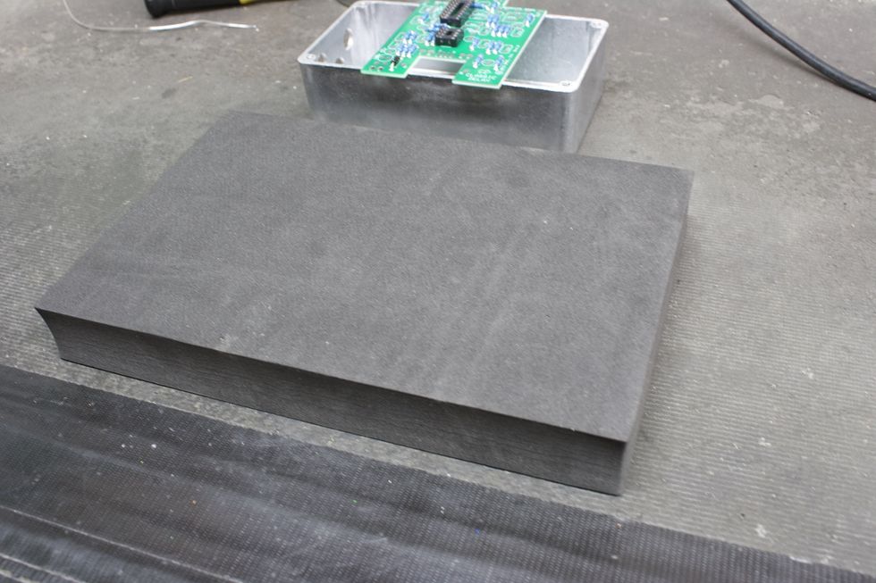
Photo 11
Place the 8-pin and 16-pin IC sockets into the corresponding pads on the top side of the PCB. We need to solder the IC socket pins from the bottom side. This means flipping the PCB over without having the IC sockets fall out. For this, I like to use a small piece of foam (Photo 11).
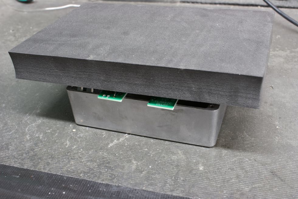
Photo 12
I place the foam on top of the PCB (Photo 12), then flip the foam and PCB simultaneously so the foam is below the PCB and the bottom side of the PCB is facing up (Photo 13).
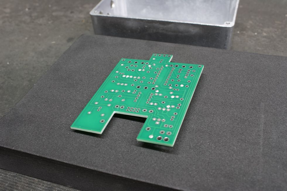
Photo 13
For this soldering step, we’ll want to solder ONLY 1 pad and then flip the board over to ensure that the IC sockets are sitting flush. If the IC sockets are not flush, go back to the bottom side and reflow that solder pad while pressing the PCB downward and keeping it parallel to the work surface. Solder the remaining pads (Photo 14).
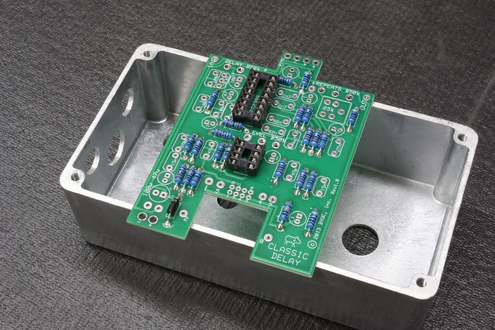
Photo 14
Step 7: Soldering the Voltage Regulator (page 12)
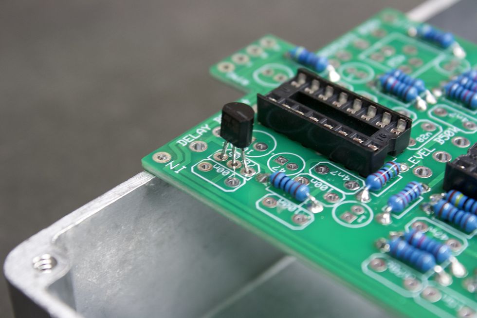
Photo 15
Place the voltage regulator into the three corresponding pads, while keeping mindful of the orientation. The flat side needs to match the outline on the PCB. Now, we’re ready to solder. This can be done from either side. Flush-cut the excess lead and we’re done here (Photo 15).
Step 8: Soldering the Trim Pot (page 13)
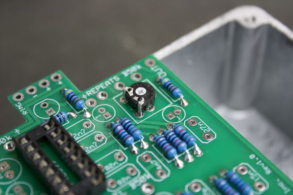
Photo 16
Place the trim pot (Photo 16) into its corresponding pads. For the trim pot provided, I found it easiest to solder the two exposed legs from the top side (Photo 17) and then the remaining leg from the bottom side.
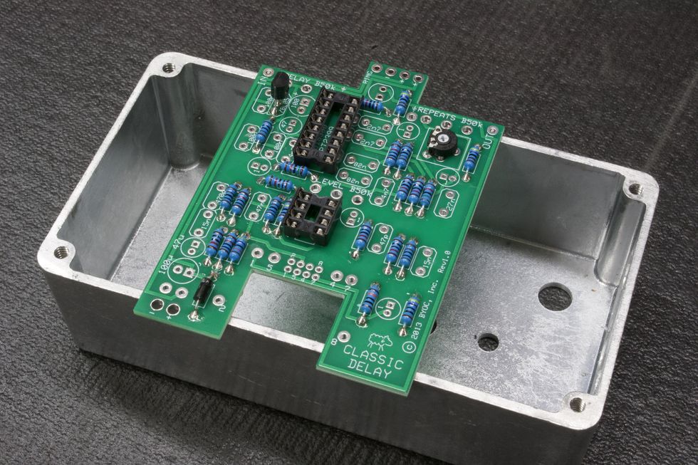
Photo 17
Step 9: Soldering Ceramic and Film Caps (page 14)
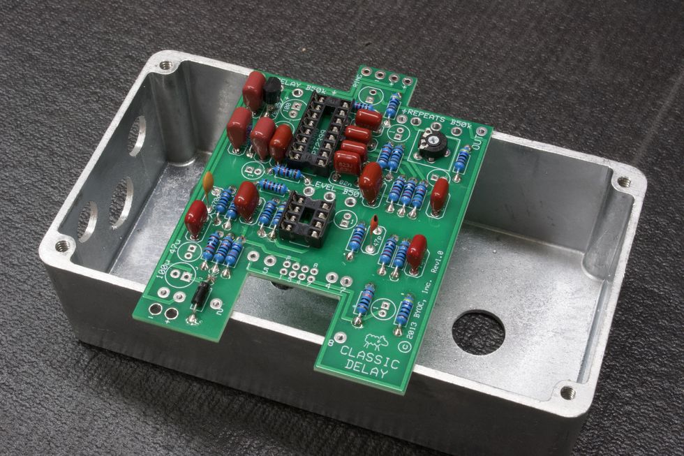
Photo 18
Place all ceramic (pill-shaped) and film (red) caps into their respective locations. Again, use page 7 of the instructions as a reference for identifying the correct capacitors (i.e. 100n film cap, which may say “104” or “.1” or “u1” on the body). We’ll need to solder the pads from the bottom side. So, once again, the piece-of-foam trick can be your friend here. Flush-cut the excess lead and we’re done (Photo 18).
Tip: An alternate method would be to bend the leads away from each other so they stay in place when the PCB is flipped over (Photo 19).
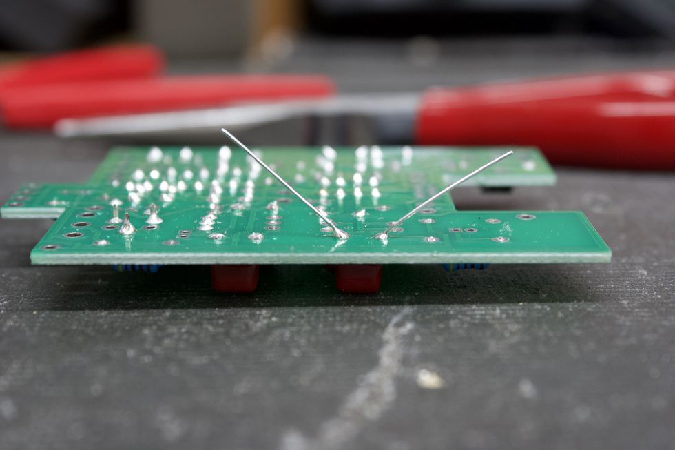
Photo 19
Step 10: Soldering Electrolytic Caps (page 15)
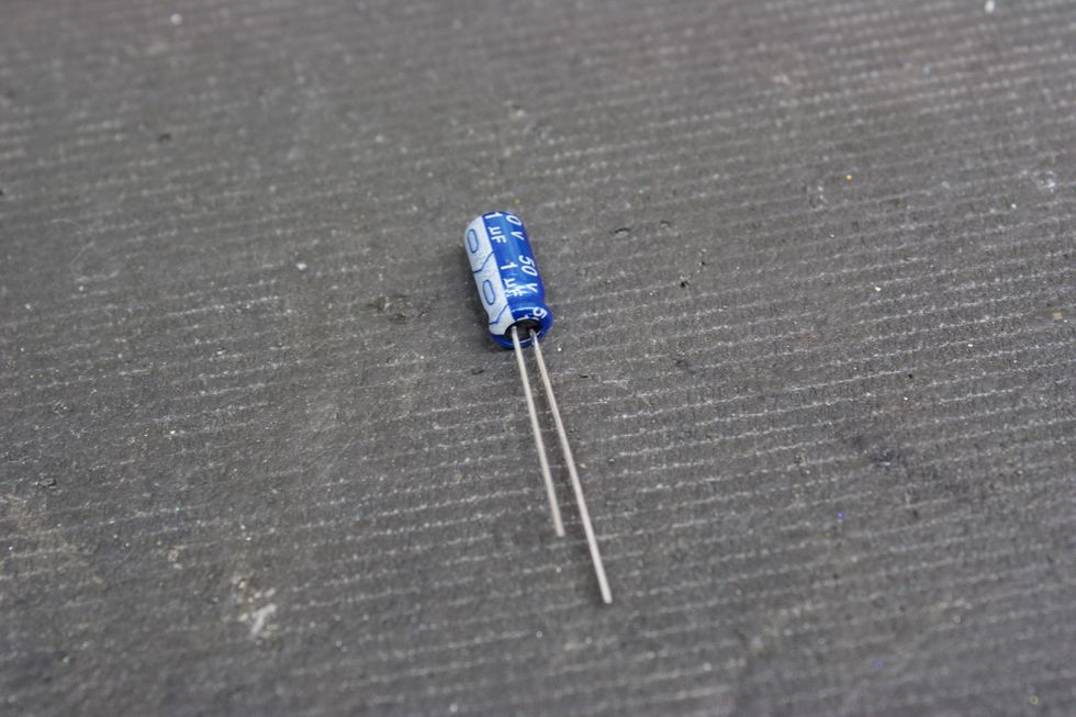
Photo 20
Let’s do the same thing here as we just did in Step 9. One thing to note is that electrolytic capacitors are polarized and need to be populated in the correct orientation. This is denoted on both the PCB and the component itself. On the PCB, the positive pad is denoted by the square pad. On the electrolytic capacitor, the positive lead is the longer leg. Additionally, the negative lead of the cap also corresponds to the white strip on the body (Photo 20).
So, let’s go ahead and populate the caps and solder them with either the foam trick or by bending the leads. Flush-cut the excess lead and we’re done (Photo 21).
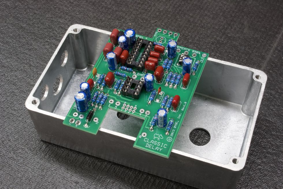
Photo 21
Step 11: Battery Snap and Hook-Up Wire
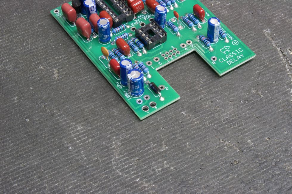
Photo 22
This DIY kit offers a battery option for those that feel so inclined. (See page 17 of the instructions.) For this step, we’ll need to connect the battery snap to the PCB. Before soldering, we’ll want to first feed the two wires through the holes directly below the solder pads. These holes act as strain relief for the battery snap and have + and - signs next to them (Photo 22). Then, simply solder the red wire to the positive (+) pad and the black wire to the negative (-) pad (Photo 23).
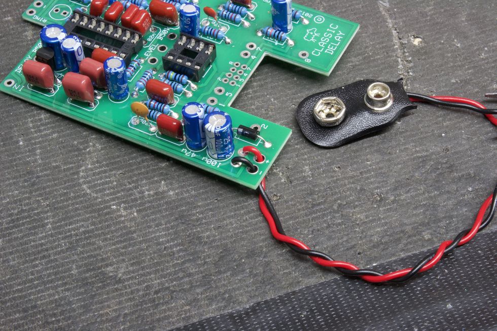
Photo 23
Next, we need to cut and strip the included wire (page 18). We need four 2.5" pieces of wire, and one 1.5" piece (Photo 24).
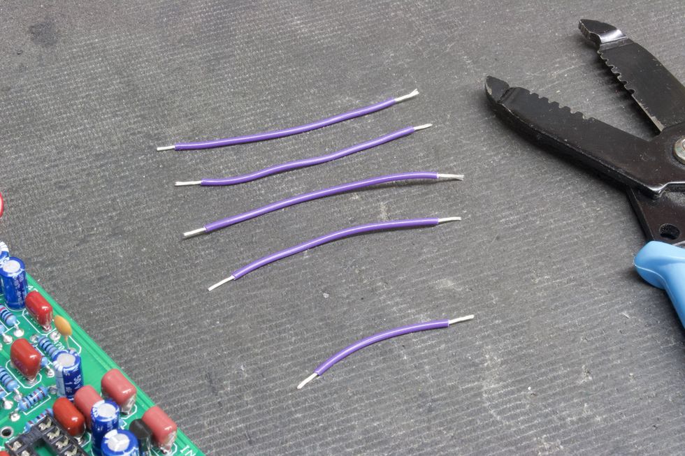
Photo 24
Place the 2.5" wires into the top side of the solder pads for in, out, and the two courtesy grounds—all handily marked. Then, solder from the bottom side. Do the same for the 1.5" wire going to the ring pad (Photo 25).
Tip: If painting the enclosure is desired, this is the last chance you’ll have to do it. After this, there will be components mounted to the chassis.
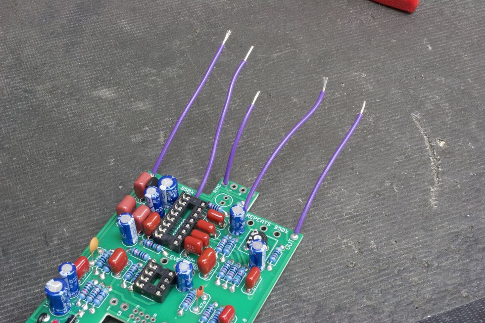
Photo 25
Step 12: Install DC Jack (page 19)
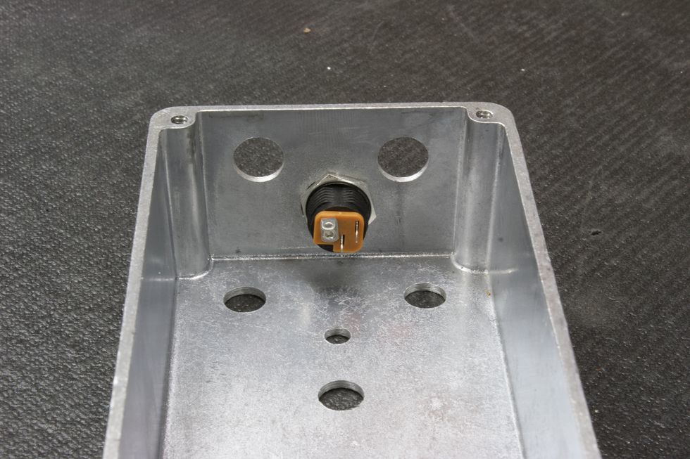
Photo 26
Place the DC jack into the large hole on the back heel of the enclosure and tighten the nut using a 14 mm (9/16") wrench (Photo 26).
Step 13: Potentiometers and Status LED (pages 20 and 21)
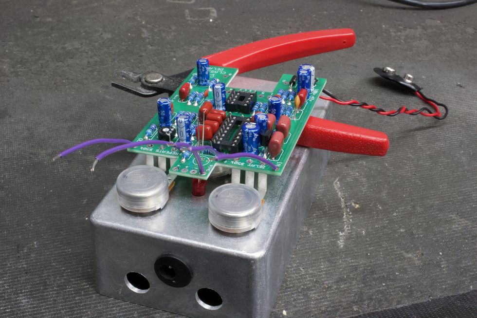
Photo 27
The included instructions for this next part have you mate the PCB to the inside of the enclosure. This will help line up the pots and LED. However, afterwards it will make soldering the remaining wire more difficult. Here’s a trick we can do that gives us the benefits of using the enclosure to help with pot alignment without needing to take the PCB out afterwards to solder the remaining wires. What we’ll want to do is simply use the face of the enclosure to hold the pots and set the LED height. Additionally, we can use the flush cutters to help balance the PCB (Photo 27). Be sure to have the long lead of the LED mate with the square pad, then solder away!
Step 14: Final Hook-Up Wire
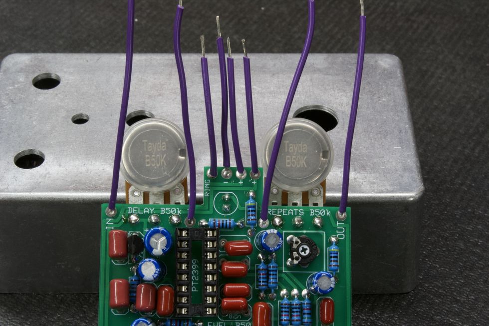
Photo 28
My steps continue to vary slightly from the instructions throughout the rest of the build, so you might want to do a side-by-side comparison. Let’s finish the wire for the DC jack next. Cut and strip three 1.5" pieces. These need to be placed into the three power pads at the top of the PCB marked -, +, + , as in Photo 28.
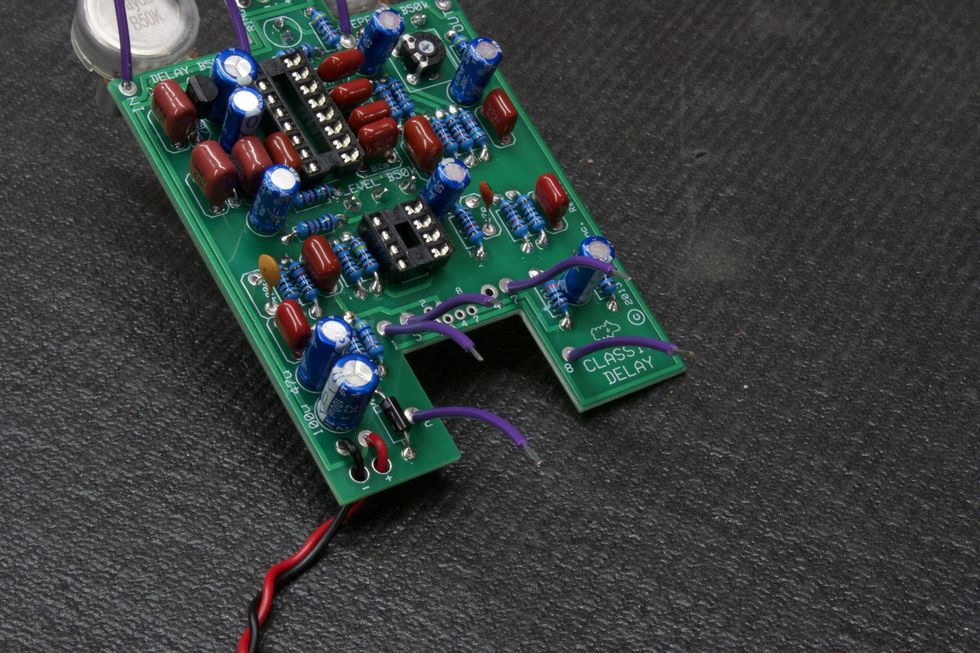
Photo 29
Next, cut and strip five more 1.5" pieces. Place these in the footswitch pads at the bottom of the PCB marked 1, 2, 5, 7, 8 as shown in Photo 29.
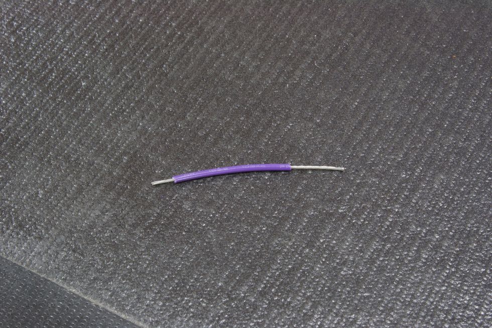
Photo 30
Last wire! Cut one 1.5" piece. Only for this one, strip half an inch off of one side (Photo 30). Place the short-stripped side into the footswitch pad labeled 4.
Step 15: Footswitch prep
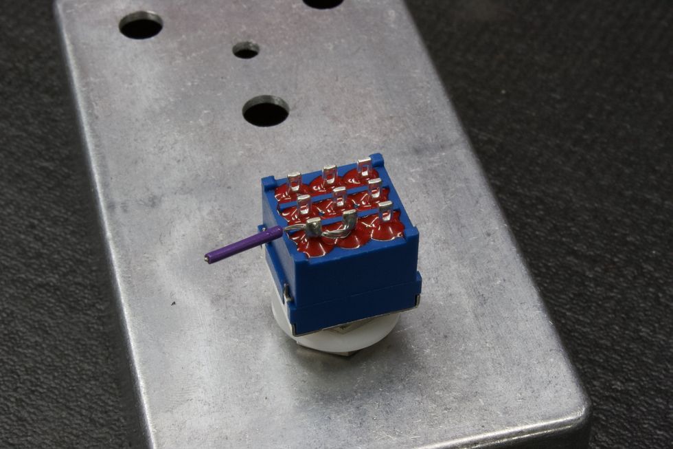
Photo 31
For the footswitch, we need to jump lugs 3 and 6. To do this, we’ll use the remaining wire. Place the footswitch into the correct hole on the face of the enclosure. Then, cut a 1" piece of wire and strip half of it. Feed the exposed wire through lug 3 and into lug 6 and then solder both (Photo 31). Cut the excess wire.
Step 16: Insert the IC
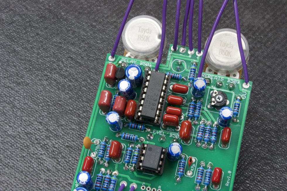
Photo 32
Now, we’re ready to insert the integrated circuits into their respective sockets. These need to be placed in the correct way, and there are two ways to identify them. Pin 1 is the top left leg of the IC—which is the rectangular black object in Photo 32. These legs are marked with a small dot in the top left corner or the upside of the IC is marked with a debossed half circle.
Step 17: Mounting and Final Soldering
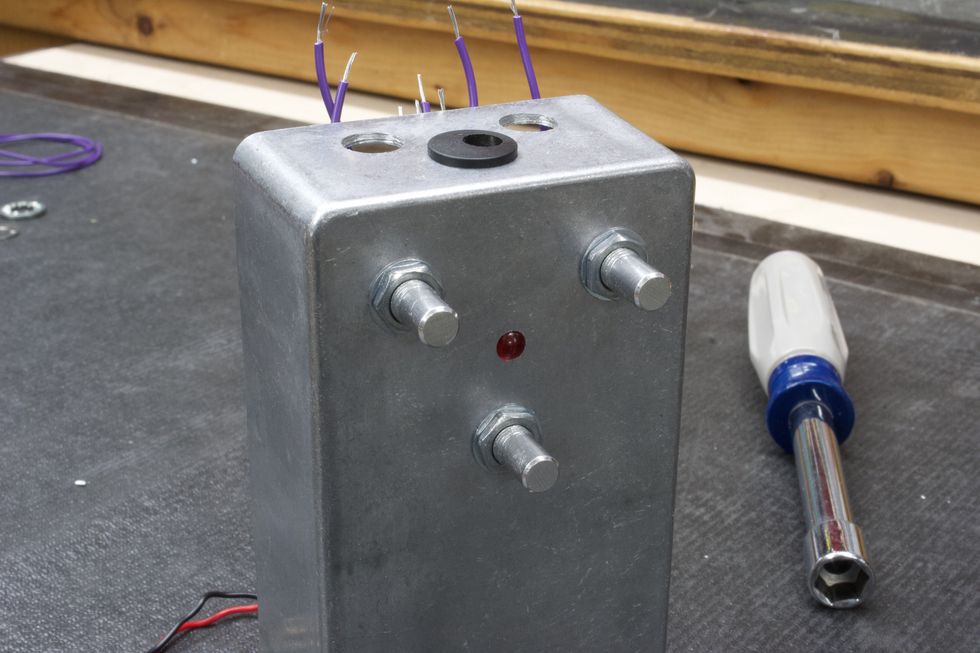
Photo 33
PCB: Now for the real fun! We’re ready to start inserting chassis-mounted components. Let’s start with the populated PCB. Place the PCB with the three pots lining up with the drilled holes, place the pot washers on the shafts, and then tighten the pot nuts using a 10 mm (25/64") nut driver/wrench, for the results in Photo 33.
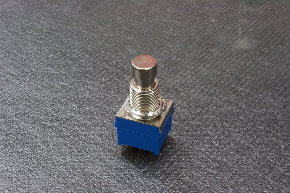
Photo 34
Footswitch: Now that the PCB is securely tightened, let’s go ahead and do the same for the footswitch. Remove all hardware from the footswitch bushing except for one nut and the lock washer (Photo 34).
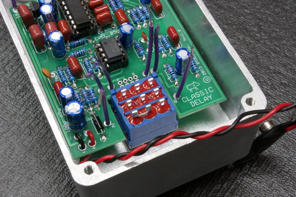
Photo 35
Feed the footswitch through the footswitch hole, making sure that the footswitch has the two poles that we soldered together facing the bottom left (Photo 35).
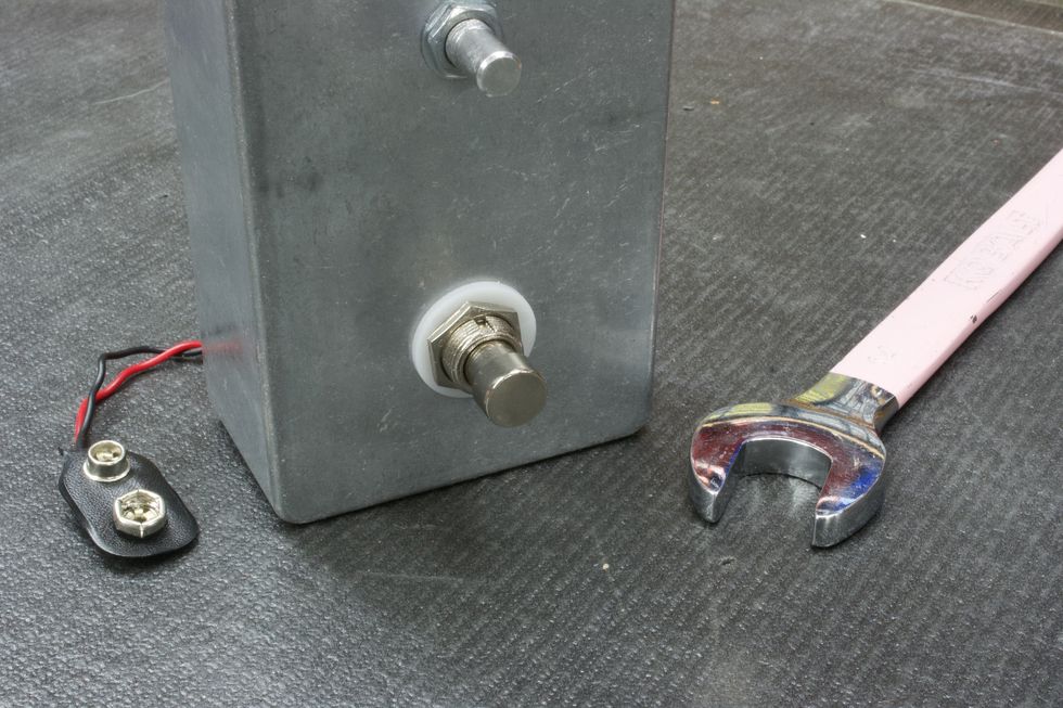
Photo 36
Next, place the plastic washer onto the bushing (optional), and tighten the hex nut with a 14 mm (9/16") wrench (Photo 36).
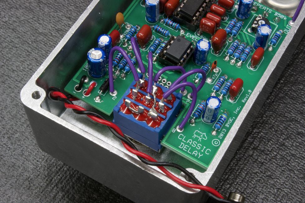
Photo 37
Lets go ahead and solder the footswitch wires to their respective footswitch poles (Photo 37). See the instructions’ page 26 for pole-numbering reference.
Tip: Solder from the top row down—i.e. 1, 4, 7, then 2, 5, 8.
Another tip: Remember that the wire for pole 4 also connects to pole 9.Step 18: DC Jack
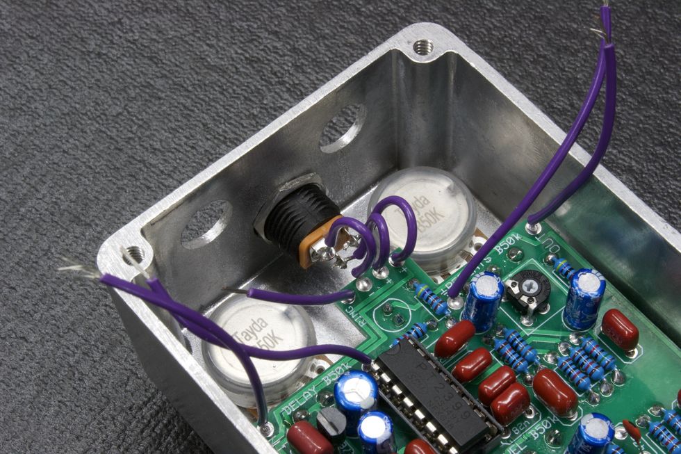
Photo 38
Next, we’ll need to solder the three wires that go to the DC jack, as explained in page 22 of the instructions. Start with the middle wire, since it sits the lowest and will be easier to get at without the other two wires in the way (Photo 38).
Step 19: Audio Jacks
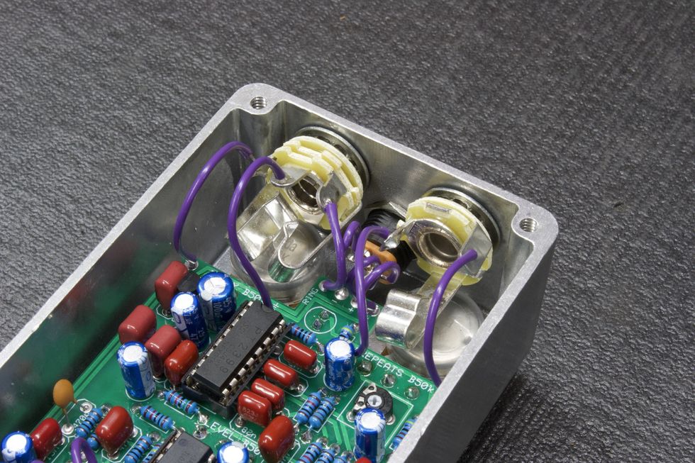
Photo 39
The last chassis-mounted components are the two audio jacks. Let’s do the stereo input jack first. Go to page 24 of the instructions to see how these jacks are oriented. The lock washer goes on the bushing first, then gets placed into the hole to the left of the DC jack. Then, place the washer onto the bushing and tighten the hex nut with a 1/2" nut driver/wrench.
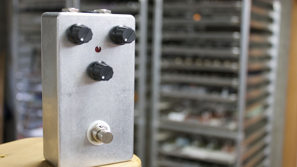
Follow the same steps for the mono output jack. And then, it’s the final soldering step: Solder the wires to the appropriate lugs on the audio jacks (Photo 39), as on instructions page 28. Then, finally, place the knobs on, tighten them down, and we’re done!
- The DIY Relic Job—Fantasy or Reality? ›
- DIY - Premier Guitar ›
- DIY Pedalboard Build ›
- Reader Guitar of the Month: Strat Style ›
- Are You Throwing Away Money Cleaning Your Shop? - Premier Guitar ›
Unleash your inner metal icon with the Jackson Lee Malia LM-87, a high-performance shred-ready axe designed in collaboration with Bring Me The Horizon guitarist Lee Malia. Featuring custom Jackson signature pickups, a fast D-profile neck, and a TOM-style bridge for rock-solid stability, this signature model is a must-have for commanding metal tone and smooth playability.
British metal icon and Bring Me The Horizon guitarist Lee Malia has partnered with Jackson to create his signature LM-87, a shred-ready axe built for heavy riffing and alternative modern metal. As a founding member and lead guitarist of the Grammy-nominated band, Malia is renowned for his aggressive playing style and intricate solos. This high-performance guitar matches his demanding musicality.
With its offset Surfcaster™ body shape and vintage appeal, the LM-87 melds classic design with modern appointments. The thin open pore finish on the bound Okoume body and neck exudes organic style, while the unique 3-ply pickguard and chrome hardware add striking accents. The fast D-profile 3- piece okoume neck allows smooth riffing across the bound amaranth fingerboard.
Custom Jackson signature pickups, including a bridge humbucker with push-pull coil-split, equip the LM-87 with versatile tone-shaping options to fulfill Malia's sonic vision. The TOM-style bridge with anchored tailpiece and fine tuners provides rock-solid stability for low tunings and heavy picking.
Designed in close collaboration with the legendary guitarist, the Jackson Lee Malia LM-87 is built for shredding. Its blend of vintage vibe and high-performance features make this signature model a must-have for players who value commanding metal tone and smooth playability.
The Tune-o-matic bridge with an anchored tailpiece and fine tuners offers enhanced tuning stability and precise, incremental adjustments. This setup ensures consistent pitch control, improved sustain, and easier fine-tuning without affecting overall string tension.
The guitar’s three-piece set-neck guitar with graphite reinforcement offers exceptional strength, stability, and resistance to warping. The multi-piece construction enhances sustain and tonal clarity, while the graphite reinforcement adds extra durability and prevents neck shifting due to humidity or temperature changes. This design ensures a solid, reliable performance with improved resonance and longevity.
Features Include:
- Okoume body
- Three-piece okoume set neck construction with graphite reinforcement
- 12"-16" compound radius amaranth fingerboard
- 3-ply pickguard
- Chrome hardware
- Custom wound Jackson LM-87 pickups
- Volume with push-pull coil-split and tone control
- TOM-style bridge with anchored tailpiece and fine tuners
- Gig bag included
The Jackson LM-87 carries a street price of $899.99.
For more information, please visit jacksonguitars.com.
Unleashing the Pro Series Signature Lee Malia LM-87 | Jackson Guitars - YouTube
Jackson Pro Series Signature Lee Malia LM-87 Electric Guitar - Open Pore Black
Pro Series Lee Malia Signature LM-87 Open Pore BlackWith a bit of downtime back in Nashville, co-shredders-in-chief Megan and Rebecca Lovell joined Shred With Shifty to deconstruct their face-melting leads on “Summertime Sunset,” off of their 2022 record Blood Harmony.
The Georgia-born, Nashville-based roots-rock outfit Larkin Poe have had a busy year. Last summer, they toured across the U.S. supporting Slash, and released their seventh studio album, Bloom, on January 22. With a bit of downtime back in Nashville, co-shredders-in-chief Megan and Rebecca Lovell joined Shred With Shifty to deconstruct their face-melting leads on “Summertime Sunset,” off of their 2022 record Blood Harmony.
The Lovells grew up reading sheet music and learning violin via the Suzuki method—there was little room for going off the beaten path until they fell in love with Jerry Douglas’ dobro playing on Alison Krauss records. Rebecca took up the mandolin, while Megan went for the dobro and the slide side of things. It took a while for them to get comfortable turning up from their bluegrass roots, but eventually they built Larkin Poe’s amplified, blues-rock sound.
First up, Rebecca, playing a pristine ’60s SG, shows how she put together her stinging, fuzzy solo by “hunting and pecking out” melodies in her mind, building up the chops to follow her intuition. Then Megan, playing a Rickenbacker-inspired lap steel of her own design through a Rodenberg TB Drive, details her dizzyingly fast slide acrobatics, and her particular “rake” technique that she copped from Jerry Douglas and Derek Trucks.
Tune in to hear them talk about how to sustain family relationships while going professional, keeping music community-minded, and whether or not they’ll go back to bluegrass.
If you’re able to help, here are some charities aimed at assisting musicians affected by the fires in L.A:
https://guitarcenterfoundation.org
https://www.cciarts.org/relief.html
https://www.musiciansfoundation.org
https://fireaidla.org
https://www.musicares.org
https://www.sweetrelief.org
Credits
Producer: Jason Shadrick
Executive Producers: Brady Sadler and Jake Brennan for Double Elvis
Engineering Support by Matt Tahaney and Matt Beaudion
Video Editor: Addison Sauvan
Graphic Design: Megan Pralle
Special thanks to Chris Peterson, Greg Nacron, and the entire Volume.com crew.
The legendary Louisville rockers brought tons of vintage tone tools on the road this year.
My Morning Jacket’s Is, their 10th album, released on March 21, and as we reported in our feature on the band in our May print issue, it showcased a band exercising their classic strengths as well as newfound vision and curiosity. Helmed by superstar producer Brendan O’Brien, Is finds MMJ at their anthemic, psychedelic best.
We caught up with Carl Broemel for a Rig Rundown back in 2015, but on this year’s tour, PG’s John Bohlinger checked in with all three axemen—Jim James, Broemel, and bassist Tom Blankenship—to hear about their road rigs. In Broemel’s estimation, they’re lazy—they just like to bring everything.
Brought to you by D’Addario.
Three's a Crowd
This gorgeous Gibson Jimi Hendrix 1967 SG Custom, aged by Murphy Labs, initially had three humbuckers, but James kept hitting his pick on the middle pickup, so it got the yank—as did the hefty bridge and Maestro Vibrola system, which were replaced with a simple stopbar tailpiece.
Mirror Image
James picked up this 1998 Gibson Flying V right around when My Morning Jacket got started. He traced and ordered the flashy mirror pickguard himself. It’s got Gibson pickups, though James isn’t sure of the models.
Jim James' Jimmy
James plucked this one-of-a-kind from Scott Baxendale’s collection of restored vintage guitars. He guesses it’s either an old Kay or Harmony guitar, but the decorations, including the custom plastic headstock plaque, make exact identification difficult. But it was clear this one was meant for James, since it has his name on it.
Elsewhere backstage is James’ Epiphone Jim James ES-335, a custom shop Fender Telecaster and Strat, a 1967 Gretsch Chet Atkins Country Gentleman, and a Gibson Barney Kessel.
Make Love, Not War
James loves repurposing old military equipment for creative, peaceful purposes, which is how this old radar system came to be a part of his live amplification kit. Along with the old tech, James runs two 3 Monkeys Orangutan heads through a 3 Monkeys cab.
Jim James' Pedalboard
James’ board is built around a pair of GigRig QuarterMaster switching systems, which lets him navigate the stomps you see here: a Devi Ever US Fuzz, Boss BD-2w, SoloDallas Schaffer Boost, Boss OC-2, EarthQuaker Devices Spatial Delivery, Strymon blueSky, EQD Ghost Echo, Malekko Spring Chicken, ISP Deci-Mate, Electro-Harmonix Mel9, UA Starlight Echo Station, and UA Astra Modulation Machine. A D’Addario Chromatic Pedal Tuner duo keep things on pitch, a Strymon Zuma and Ojai pair handle the power, and a Radial SGI-44 line driver maintains clarity.
Arts and Crafts Night
One night while a bit tipsy, Broemel took out his paint pens and set to work on this Gibson Les Paul Standard Faded, resulting in this masterpiece. He also removed the pickup selector switch; even though the neck pickup remains, it never gets used.
Relic By Broemel
This 1988 Les Paul Standard predates the band, and Broemel has given it its aged finish over the years—on one occasion, it fell out of a truck. It’s been treated to a Seymour Duncan pickup upgrade and occasional refrets when required.
Carl's Creston
This Creston Lea offset has two Novak lipstick pickups in the neck, with a switch to engage just one or both, plus a low-end roll-off control. It’s finished in the same blue-black color as Broemel’s house and sports a basil leaf on the headstock in tribute to Broemel’s son, Basil.
Also in the wardrobe are a shiny new Duesenberg tuned to open G, and a custom shop Fender Telecaster with a fattened neck and Bigsby to swing it closer to Broemel’s beloved LPs.
Milk Route
Broemel routes his GFI Ultra pedal steel, which is tuned to E9, through a board which includes a Milkman The Amp, which is projected through the speaker of a Fender Princeton Reissue combo. Operated with another GigRig QuarterMaster, the board also includes an Eventide H9, Moog MF Delay, Fender The Pelt, MXR Phase 90, EHX Nano POG, Xotic Effects EP Booster, Source Audio C4, and a Peterson StroboStomp HD.
Side-Carr
This time out, Broemel is running two Carr Slant 6V heads in stereo.
Carl Broemel's Pedalboard
Broemel commissioned XAct Tone Solutions to build this double-decker board, which depends on a GigRig G3S switching system. From top to bottom (literally), it includes a Boss TU-3, Durham Electronics Sex Drive, JAM Pedals Tubedreamer, Source Audio Spectrum, JAM Retrovibe, MXR Phase 100, Fender The Pelt, Origin Effects SlideRIG, 29 Pedals EUNA, two Eventide H9s, Kingsley Harlot V3, JAM Delay Llama, Merix LVX, Hologram Chroma Console, and EHX POGIII. A wah and Mission Engineering expression pedal sit on the left side, while a Lehle volume pedal and Gamechanger Audio Plus hold down the right edge.
Utility units include two SGI TX interfaces, two Strymon Ojais and a Strymon Zuma, and a Cioks Crux.
More From the Creston Crew
Blankenship, too, has brought along a few guitars from Lea, including these Precision-bass and Jazz-bass models. The dark-sparkle P-style rocks with GHS flatwound strings, while the natural-finish J-style has roundwounds.
Emperor's New Groove
Blankenship just got these brand-new Emperor cabinets, through which he cranks his Mesa Boogie WD-800 Subway heads.
Tom Blankenship’s Pedalboard
Like James, Blankenship uses a GigRig QuarterMaster to jump between his effects. After his Boss TU-3, that includes an Origin Effects Cali76, DigiTech Whammy Ricochet, Pepers’ Pedals Humongous Fuzz, MXR Bass Octave Deluxe, Tronographic Rusty Box, and EHX Bassballs Nano. A Voodoo Labs Pedal Power 2 Plus lights things up, and a Radial SGI TX keeps the signal squeaky clean.
Shop My Morning Jacket's Rig
EarthQuaker Devices host Echo Reverb Pedal
ISP Technologies DECI-MATE Micro Noise Reduction Pedal
Electro-Harmonix Mel9 Tape Replay Machine Pedal
EarthQuaker Devices Spatial Delivery Envelope Filter Pedal
Universal Audio UAFX Starlight Echo Station Delay Pedal
Universal Audio UAFX Astra Modulation Machine Pedal
Fender Custom Shop Stratocaster
Fender introduces the Stories Collection Mike Campbell Red Dog Telecaster, paying tribute to the iconic guitarist's heavily modified instrument. Featuring two signature humbuckers, a custom single coil bridge pickup, Bigsby tremolo, and a unique "Destruct" circuit, this Telecaster allows players to channel Campbell's legendary tone and style.
Today, Fender Musical Instruments Corporation (FMIC) and the Fender Custom Shop (FCS) introduce the newest member of the ‘Stories Collection’ family—a series of instruments that pays tribute to iconic Fender guitars and basses that have been uniquely modified by the legendary artists who played them. Mike Campbell, the tasteful and versatile player who is responsible for some of Tom Petty and the Heartbreakers’ most memorable riffs, has teamed up with Fender and the Custom Shop to develop the Stories Collection Mike Campbell signature guitars - the Red Dog Telecaster and FCS Limited Edition Masterbuilt 1972 “Red Dog“ Telecaster—two reproductions of Campbell’s stunning and heavily modified Telecaster that gives players the opportunity to create their own sonic identity through the framework of one of rock and pop’s greatest guitar players.
“Telecasters are the heart and soul of rock and roll music and this one is a beautiful instrument,” said Mike Campbell. “I could tell The Red Dog was special as soon as I picked it up. It felt like it was in the right place at just the right time. The humbuckers give it so much power and such a wide variety of tones while the destruct button really sets it apart from just about any other tele.”
The tale of the Red Dog Telecaster began when one of Campbell’s former students living in Florida offered to sell him a guitar. However, after seeing the guitar in question, it became clear that this was no standard instrument pulled from the rack. Campbell was presented with a bright red Tele equipped with humbuckers in the neck and middle position, a Bigsby tremolo and, perhaps the guitar’s most idiosyncratic flourish, an onboard electronic boost dubbed the “destruct” circuit. As any other lifelong guitar devotee would, Campbell bought this glorious Frankenstein of an instrument without a moment’s hesitation. The Red Dog was subsequently used most memorably on the Heartbreaker’s track “Refugee” and is prominently featured in the song’s music video. All throughout his storied career playing with Tom Petty, as a session guitarist, alongside Fleetwood Mac and touring the world with his solo act The Dirty Knobs, this singular Telecaster has been inextricably linked to Campbell’s career and legacy as one of rock and roll’s finest players.
The Stories Collection Mike Campbell Red Dog Telecaster offers the same level of craftsmanship and sonic capability at a more accessible price point. The two signature Mike Campbell humbuckers in the neck and middle position bring a low-end growl and high octane output that sets it apart from other Telecaster guitars. However, the custom single coil bridge pickup delivers the caliber of twang that people worldwide associate exclusively with Tele guitars. A Bigsby B5F tremolo allows players to extenuate riffs and solos with an additional level of flourish and attitude. Perhaps the Red Dog’s most exciting feature lies beneath the surface—the “Destruct” circuit. With the push of a sleek silver button on the control plate, an added 34 dB of gain can be activated for complete tonal dominance.
“It’s our mission to honor the legacy and sonic character that Mike Campbell has infused into every note played on his beloved ‘Red Dog’ Telecaster®,” said Justin Norvell, Executive Vice President of Fender Products. “Every scratch, modification, and battle scar tells a story, and with these meticulously crafted recreations, we’re giving players everywhere the chance to channel that same timeless energy and write their own musical history.”
While the Red Dog Telecaster came into his hands already modified, its custom features were universal and powerful enough to elevate Campbell’s personal playing style and the same can be said for Fender’s painstakingly detailed and powerfully crafted recreations. The FCS Limited Edition Masterbuilt 1972 “Red Dog” Telecaster is a jaw dropping representation of the instrument as it exists today—dings, paint chips, dents and all by FCS’s Senior Masterbuilder Dennis Galuska. Outfitted with vintage replica Arcane, Inc. pickups and signature “Destruct” boost circuit wired by Analogman, this custom Telecaster can achieve the same biting jangle heard on “Refugee.” Features include a flat sawn maple neck with custom Oval “C” back shape, 7.25” radius fingerboard, 21 vintage upgrade frets, 5-way pickup sector and vintage style Jazzmaster bridge with threaded saddles.
“The ‘Red Dog’ Telecaster® is a testament to how a heavily modified instrument can be both deeply personal and universally cherished,” said Chase Paul, Director of Product Development - Fender Custom Shop. “There’s an undeniable magic in an instrument that evolves alongside its player, and every modification on this guitar serves a purpose, working together to create something greater than the sum of its parts. Dennis Galuszka and the Custom Shop dedicated countless hours to faithfully recreating every detail, bringing players and fans as close to Mike’s legendary Tele® as possible.”
Stories Collection Mike Campbell Red Dog Telecaster® ($3,499.99) Revered for his tasty rhythms and fiery leads, Mike Campbell is responsible for many of the iconic hooks from the Tom Petty and the Heartbreakers catalog. For decades now his faithful Fender guitars have been at the heart of his trusted formula for award-winning tone.Campbell bought what became known as the “Red Dog” from a former guitar student in Florida, complete with Bigsby tremolo and a powerful onboard boost, known as the “Destruct” circuit. Mike’s iconic 1972 Red Dog Telecaster is featured on the Damn the Torpedoes track “Refugee” and can be seen in the accompanying music video. The Stories Collection Mike Campbell “Red Dog” Telecaster features an Heirloom™ nitrocellulose lacquer “Red Dog Red” finish, 1-piece maple neck with 7.25” radius fingerboard and 21 vintage-style frets as well as an onboard “Destruct” boost circuit. The custom Mike Campbell Red Dog pickup set features two vintage-style humbuckers and a single-coil Telecaster bridge pickup, Bigsby B5F tremolo and a custom Red Dog neck plate. Custom accessories include a vintage-style case, strap, picks and certificate of authenticity.
Unique, versatile and utterly original, The Mike Campbell “Red Dog” Telecaster pays tribute to a veteran Heartbreaker with a serious knack for writing extraordinary songs and delivering catchy, captivating and magnificent guitar parts.
Fender Custom Shop Limited Edition Masterbuilt Mike Campbell 1972 “Red Dog” Telecaster® ($20,000.00) With raw, powerful riffs and explosive leads, Mike Campbell firmly established himself as one of the greatest guitarists and songwriters in music history—and throughout his accomplished career, Fender guitars played in integral role in his creative expression. One of his most noteworthy instruments was his modified three-pickup Telecaster that would come to be known as the “Red Dog.” Fender Custom Shop Senior Masterbuilder Dennis Galuszka partnered with Mike to recreate this incredible guitar. From beautifully faded red metallic finish to the worn and Bigsby B5 vibrato tailpiece, every nick, ding and scratch was meticulously replicated to bring this tribute guitar to life. Loaded with vintage replica Arcane, Inc. pickups and a “Destruct” boost circuit wired by Analogman, this Tele plays, sounds and feels just like the guitar heard on “Refugee.” Its two-piece select alder body and custom-shaped, one-piece maple neck feature a well-loved Relic® lacquer finish, while the hardware is aged to look like it’s been played for the last five decades. Wonderfully unique and with a storied past, the Limited Edition Masterbuilt Mike Campbell 1972 “Red Dog” Telecaster is a fitting homage to such an incredibly captivating and inspiring musician. Other premium features include flat sawn maple neck with custom Oval “C” back-shape, 7.25” (184.1 mm) radius, 21 vintage upgrade (45085) frets, 5-way switch, 3-ply parchment pickguard, vintage-style Jazzmaster® bridge with threaded steel saddles, vintage-style “F”-stamped tuning machines, bone nut, two American Vintage ‘65+ string trees with nylon spacers, deluxe hardshell case, strap and certificate of authenticity.
For more information, please visit fender.com.