Basic Modding Supplies
Each of the modifications discussed here require the following:
• Soldering iron
• 60/40 rosin-core solder (don’t buy lead-free)
• Solder sucker (not mandatory, but very helpful)
• Desoldering braid
• Small side cuts/wire cutters
• Felt-tip marker
If you’ve ever owned an Ibanez TS9 Tube Screamer or a Boss SD-1 Super Overdrive, you’ve probably noticed two things: You like the way they sound, but they could also really use a little something more. We’ve come up with some custom modifications that we feel give these pedals that “something more”—and the best part is that you can do the mods on your own! All you need to be able to do is follow instructions and know how to solder and desolder. (If you haven’t soldered before—or if you are a bit rusty and need a refresher—go to YouTube and watch CuriousInventor.com’s video “How and WHY to Solder Correctly,” and ExpertVillage.com’s “How to Solder: Removing Solder.”)
Modifying pedals can be an intensely rewarding experience—it’s like creating an entirely new pedal that feels and breathes differently than before. Sometimes it’s a battle, a game of wits, with you pitted against a mechanism that you so bravely took apart with the intentions of creating something more wonderful and awe inspiring. Sometimes it can be an emotional rollercoaster, especially if you are somewhat attached to the pedals that you are modifying. It’s very frustrating to be pumped up to play through your newly modded pedal and have it not work. That’s why it’s so crucial to follow all of the instructions outlined in this article. No one wants to break a perfectly good pedal while trying to “improve” it. Fortunately, if you follow the instructions outlined here, you’ll have an awesome-sounding pedal for you and the rest of the world to enjoy for the rest of your musical days—and that is where the fun lies.
Okay, let’s get started!
The Stages
There are generally five stages to pedal modding, depending on how successful you are with replacing and/or adding parts the first time around. Read them carefully and remember to flip back and reference them at any point during the mod process to make sure you’re on the right track. One very important warning before moving on to the stages:
Avoid the temptation to try to work on two mods simultaneously. For example, don’t try to do the true-bypass mod while doing the variable mid-control mod. Working on different mods simultaneously usually makes the troubleshooting process a nightmare. Complete one modification starting at stage 1 and going through stage 5. Once that mod is finished, start over at stage 1 with the next mod.
Stage 1: Assess Mod Difficulty
This first stage is important because it’s when you decide whether
to attempt a specific modification. The steps include:
1. Read all of the instructions.
2. Make a supply list (if one is not provided).
3. Determine the overall difficulty of the modification.
4. Decide whether or not you can pull off the mod without
adversely affecting your pedal.
This last step is very important. If you don’t feel comfortable with the mod, don’t do it! Start with something easier and work your way up to build confidence and skill. Some of the modifications we’re talking about here are pretty tricky, and they will be much more difficult (though not impossible) for beginners. Note: Neither I nor anyone at my company, Wampler Pedals, can provide technical support for these modifications or assume responsibility for pedals damaged while performing these mods. If these modifications are too difficult for you, we may be able to perform them on your pedal, depending on our workload at the time. Visit wamplerpedals.com and click the Contact link for more details.
Stage 2: Prep for the Mod
If, in stage 1, you decided the mod isn’t a good idea at the moment,
this stage includes boxing up your pedal and sending it in to us. If
you are doing the mod, the steps include:
1. Turn on your soldering iron. I do this first so that it will be up
to temperature by the time I am done with the rest of the steps.
2. Gather parts, wire, and tools as described in your supply list.
3. If you use a sponge to clean your iron’s tip, wet it now.
4. Take a deep breath.
Stage 3: Mod Time!
This is the stage where it all happens. The steps include:
1. Remove the pedal’s back panel and take pictures of how the
circuit board and other internal parts are oriented before making
any changes.
2. Take the circuit board out of the pedal’s enclosure.
Note: Some circuit boards—including those in Boss and Ibanez
units—cannot be removed all the way due to the way they are wired.
In those cases, you can make it easier to move the circuit board
around while it’s still attached to the case by loosening the potentiometers
and/or the 1/4" jacks—but be careful not to break the wires.
3. Use a felt-tip marker to mark the leads of the components that
need to be removed from the circuit on the solder side of the circuit
board. Note: If you accidentally mark the wrong component, you
can either just leave the mark on there as it will not affect the sound,
or you can lightly heat the joint with your iron to remove the mark.
4. Remove the first component and replace it with the new one
using the desoldering and soldering techniques learned in the
videos mentioned at the beginning of this article.
5. Test the pedal to make sure it still works after the new component
is in the circuit. Testing after each component change
can save you a lot of time and frustration in the troubleshooting
process, because you will know the exact point at which
the circuit failed. You don’t have to put the circuit board back
in the case—just make sure the 1/4" jacks are still connected
to the case to ensure proper grounding.
6. Continue replacing or adding parts, one at a time—and testing
the pedal after each addition or replacement—until the
mod is complete.
Stage 4: Troubleshooting
If stage 3 went well and your stompbox works properly, skip this
step. If not:
1. Relax! It’s fairly common for a pedal not to work right after
modding due to some easy-to-make mistakes.
2. Check to see if everything that is supposed to be grounded is
grounded, and that everything that shouldn’t be grounded isn’t.
Look for places where the input or output jack may be touching
the case where it shouldn’t be. Also, check that the solder side of
the circuit board is not in direct contact with the case. In the case
of the true-bypass mod, check to make sure the lugs of the footswitch
are not touching the case. Double-check all the solder joints.
Note: It often helps to use a multimeter here. For a great video
on how to use them, go to YouTube and search for AfroTechMods’
“THE BEST Multimeter Tutorial (HD).”
3. If you’re still having problems, watch Chromesphere.com’s
YouTube video called “DIY Guitar Pedal Tutorial 9: Fault
Diagnosing” to see several things you can check first-hand.
Stage 5: Final Testing
This is the most exciting stage—it’s where all your hard work pays off
with an awesome, unique, and fresh-sounding pedal. The steps include:
1. After testing the pedal with the modification completed,
carefully put the pedal back together, making sure to tighten
everything down snug—but leave the back plate off.
2. Test the pedal one last time.
3. If it still works properly, install the back plate.
Now that you know all the stages, let’s get on to the fun stuff! All of the following mods are separate projects. You can do one of them, all of them, or maybe pick and choose two or three. No matter what mods you choose to do, your pedal will sound great when you’re done. However, if you decide to do the true-bypass mod, I suggest doing it first because you’re going to remove a couple of FETs, diodes, resistors, and capacitors, which will change the tone of your pedal a bit—and you don’t want to get the tone you want dialed in with these other mods only to have it changed by making it true-bypass. Just keep in mind that in the pictures shown here, I did my true-bypass mod last so there wasn’t a big hole in the unit for all of the pictures.
MOD 1: Make Your TS9 True-Bypass
Tools and Parts for This Mod
• Power drill
• 1/2" drill bit
• Wire strippers
• 3PDT footswitch
• 2.2k–4.7k Ω resistor
• Three jumpers (these could be clippings from
the leg of a resistor or capacitor)
• Two or three 3" pieces of wire
• Needle-nose pliers (handy, but optional)
This mod requires drilling a big ol’ hole in the middle of your Tube Screamer’s case. Here goes nothing, right? I know it sounds crazy, but it has to be done so you can install the shiny new 3PDT (three-pole, double-throw) footswitch that’s necessary to make your pedal true-bypass.
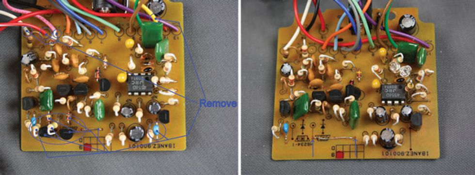
Photo 1 (left): Components and wire leads to be removed from the main TS9
circuit board. Photo 2 (right): Replace the original short jumper wire with a longer one extending
to the hole where the bottom leg of a 510k Ω resistor used to be.
1. Desolder the red-and-white-striped wire from the circuit board (upper-left corner in Photo 1) and cut the black wire that connects the input jack to the original footswitch. This allows you to remove the circuit board from the case.
2. With the circuit board removed, drill a 1/2"-diameter hole in the middle of the case where it says “TS9” (under the Ibanez logo). You may want to prop your pedal up on blocks so that the top is level and you can get a straight shot at the surface (otherwise, the hole will end up being elliptical instead of round).
3. The TS9 uses what’s called a “flip-flop” circuit to turn on and off, but with the new true-bypass switch, the parts in this circuit aren’t necessary. Remove the following:
• Two FETs
• Two 510k Ω resistors
• Two diodes
• The jumper wire
• The capacitor labeled “104” (it’s the blue cap at lower-right on this board, but it may be a different color on yours)
4. Desolder the end of the pink wire on the main circuit board that connects to the LED’s circuit board.
5. Remove the short jumper wire (bottom middle of the circuit board in Photo 2) and replace it with a longer jumper that begins at the same right-side hole as the previous jumper but extends to the hole in between where the two FETs removed in step 3 used to be. The correct hole previously contained the bottom leg of one of the 510k Ω resistors also removed in step 3.
(Note: Disregard the two clear LEDs that appear in place of clipping diodes at middle right in Photo 2—they were from a previous mod.)
6. Now that most of the board work is done, let’s move on to the footswitch. To make wiring more convenient, place it upside-down in the case, with the holes in the lugs facing you (see Photo 3). Referencing the schematic in Fig. 1:
• Connect pins 2 and 9 with a jumper wire
• Connect pins 7 and 8 with a jumper wire
Note: Make sure the jumper wires don’t touch any other lugs.
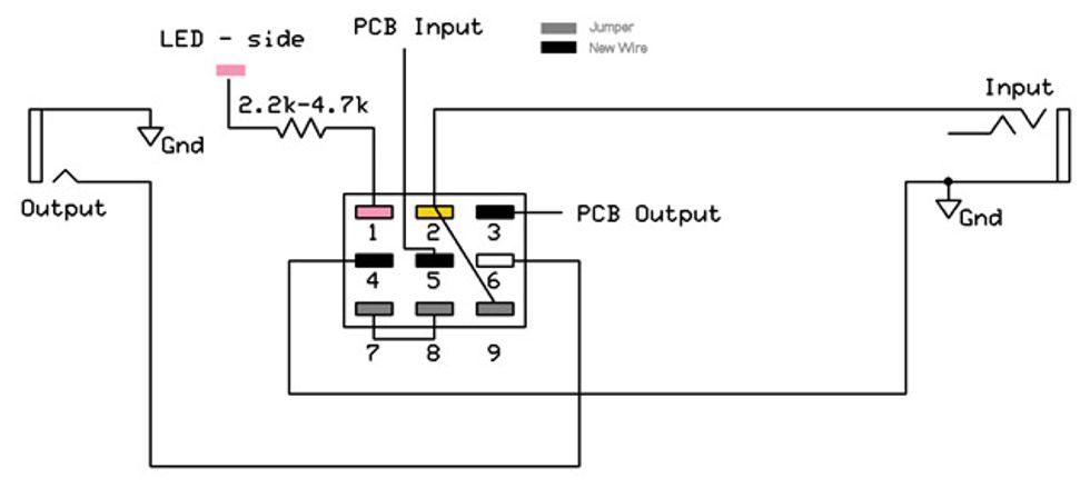
Fig. 1: Schematic for wiring a 3PDT true-bypass footswitch.
7. Desolder the yellow wire at the upper right in Photo 1 (it’s in the hole labeled “11”) from the main circuit board and solder it to footswitch pin 2. See Photo 4.
8. Solder one end of a 3" wire in the now-empty hole 11. Solder the other end to footswitch pin 5.
9. Desolder the white wire from the upper-left corner of the main circuit board (the hole labeled “1”).
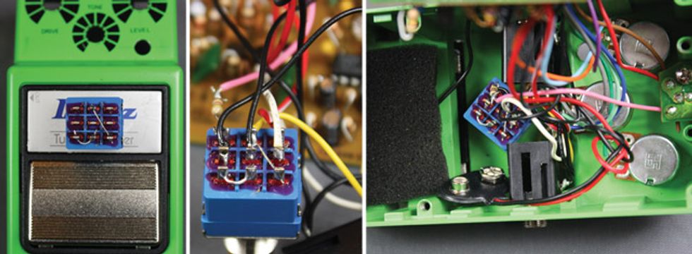
Photo 3 (left): Prop the new 3PDT footswitch
in the newly drilled hole for
convenience while soldering jumper
wires and other leads. Photo 4 (middle): The true-bypass switch
with steps 7–14 completed. Photo 5 (right): A completed TS9 true-bypass mod.
10. Solder one end of a 3" wire (or you could reuse the red-and-white-striped wire) in the now-vacant hole 1. Solder the other end to footswitch pin 3.
11. Solder the white wire from the output jack to footswitch pin 6.
12. Strip a little insulation off of the pink wire.
13. Solder one leg of your new 2.2k–4.7k Ω resistor (resistors aren’t polarized, so it doesn’t matter which leg) to the pink wire. Connect the resistor’s other leg to footswitch pin 1.
14. Solder one end of a 3" wire to the sleeve lug of the input jack, and the other end to footswitch pin 4. If you’re having trouble finding the sleeve lug, here’s how: See how the jack has three lugs, one with a yellow wire, one with a black wire going to the battery terminal, and one with a black wire going to the output jack? That last lug—the one with the black wire going to the output jack—is the one you want to solder to.
15. Connect the new footswitch to the pedal housing.
Congrats—your TS9 is now true-bypass! Your footswitch should look something like Photo 5 when it’s done and installed.
Mod 2: Alter TS9 and SD-1 Distortion by Swapping Diodes
Tools and Parts for This Mod
• Various numbers and types of diodes and/or LEDs, depending
on which symmetrical or asymmetrical mod you decide to do
You can get different shades of distortion by swapping clipping diodes in your Tube Screamer or Super Overdrive. For example, replacing the existing diodes with germanium diodes will yield a compressed, smooth fuzz sound. In contrast, silicon diodes (1n4148, 1n4001, 1n914, etc.) tend to provide a crisper, tighter, more focused sound. LEDs sound warmer, offer a great crunch, and usually make the pedal sound louder.
You can also experiment with different diode configurations. Two types of clipping can be achieved through different configurations: symmetrical and asymmetrical. Asymmetrical clipping—the type of clipping achieved in a stock Boss SD-1 circuit (see Fig. 2)—tends to yield a more dynamic and responsive overdrive resembling the feel and response of an amp overdrive. You can get asymmetrical clipping by putting two series-wired diodes in parallel with one diode oriented in the opposite direction (as shown in the mod instructions).
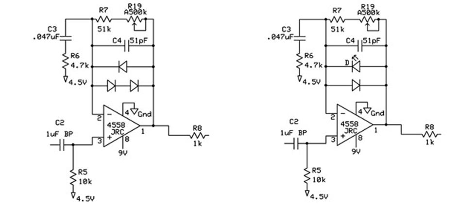
Fig. 2: Asymmetrical Clipping. A stock Boss
SD-1 schematic (left), and an SD-1 schematic
with an LED swapped out in place of the original
clipping diode to yield a louder, warmer, more
responsive feel (right).
To get more headroom out of a symmetrical clipping circuit—the type of clipping achieved in an Ibanez TS9 circuit (see Fig. 3)—you can add an extra set of diodes in series with the original diodes, or you can change both diodes out for LEDs (as shown in the diagrams). However, keep in mind that this will change how much clipping you hear.
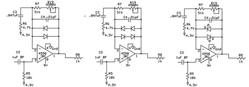
Fig. 3: Symmetrical Clipping. A stock Ibanez TS9 schematic with two silicon diodes (left), a TS9 schematic modded with two sets of series-wired diodes running parallel to each other to achieve more volume and headroom with slightly less clipping (middle), and a TS9 schematic with two LEDs running in parallel instead of the original silicon diodes, which yields more headroom and volume, with a warmer response.
When replacing diodes, make sure you orient them correctly. The stripe on the diode always goes on the same side as the bar at the tip of the triangle on the diode symbol that’s stenciled on the circuit board. For LEDs, the short leg goes towards the bar.
Now that you know more than you probably ever wanted to know about diode configurations, we’ll show you how to do some diode mods on a TS9 and an SD-1.
TS9 Asymmetrical
Clipping Mod
Let’s start by changing a Tube
Screamer’s clipping from stock
symmetrical to asymmetrical by
adding a diode pair in series.
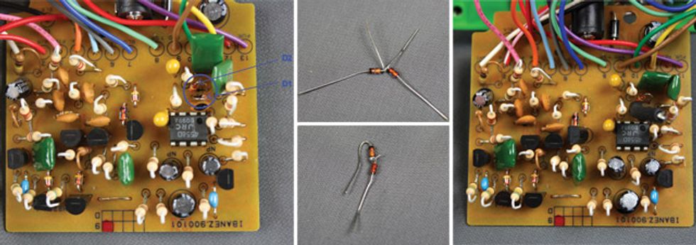
Photo 6 (left): Diodes 1 and 2 on a TS9 circuit board. Photo 7 (top middle): Wire two diodes in series by making sure their black stripes are oriented in the same direction and then wrapping the middle leads together. Photo 8 (bottom middle): Solder the diode legs together and bend the outer legs for easy installation. Photo 9. (Right) Solder the series-wired diodes’ legs back into the holes vacated in step 2. Note the black heat-shrink wrap protecting the new solder connection.
1. Locate the diodes on your TS9’s circuit board. See Photo 6.
2. Desolder diode 1 (D1) or diode 2 (D2)—it doesn’t matter which comes first. Note: I recommend using a felt-tip marker to mark which components you need to desolder on the underside of the circuit board.
3. Wire two diodes in series—either pair one stock diode with a new one or pair two brand-new diodes—by twisting their legs together as shown in Photo 7. Note: See how the black stripes are both on the left hand side of each diode? This is very important to get right—your pedal won’t work unless they are oriented correctly.
4. Solder the twisted-together legs as shown in Photo 8, and then place heat-shrink wrap or electrical tape on the exposed solder joint (not shown), and bend the legs as shown.
5. Place the series-wired diodes’ legs back through the D1 or D2 holes (depending on which you removed in step 2) and solder them in place. See Photo 9. Note: Make sure the diodes’ black stripes are on the same side as the bar on the tip of the triangle marked on the board.
Now that you know how to place diodes in series, you can read the schematics in Figures 2 and 3 and execute any of them that use series wiring.
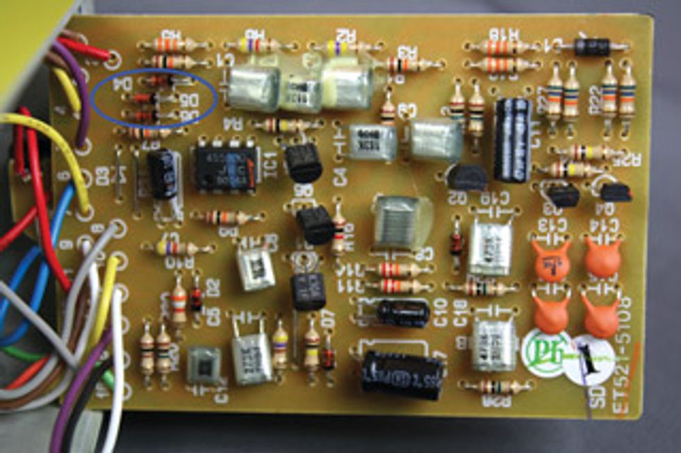
Photo 10: On the Boss SD-1’s circuit board, diodes D4, D5, and D6 can be altered in various asymmetrical and symmetrical arrangements for different feels and gain types.
SD-1 Symmetrical
Clipping Mod
The SD-1 circuit is different
from the TS9 in that it comes
standard with an asymmetrical
clipping arrangement. Take a
look at the circuit layout in
Photo 10. D4, D5, and D6 are
the clipping diodes. D5 and D6
are already in series with each
other and in parallel with D4.
If you want to make this a symmetrical
arrangement, you can
remove D5 or D6—it doesn’t
matter which—and place a
jumper wire where it used to be.
If you want a symmetrical arrangement with more headroom, I suggest leaving D5 and D6 alone and adding a diode in series with D4, just as we did in steps 3 and 4 in the previous “TS9 Asymmetrical Clipping Mod.” If you want more clipping with an asymmetrical setup, you could also place a diode in series with D4 and D6. You can try many variations of series and parallel pairings of different types of diodes, and it’s a bit easier with the SD-1 as compared to the TS9 because of the SD-1’s setup and its roomier circuit board. So don’t be afraid to experiment—just make sure you don’t put your diodes in backward. If you do, it won’t hurt anything, but your pedal won’t work right. All you have to do is turn them around and you should be good to go.
Mod 3: Tweak Feedback in Your SD-1 or TS9
Tools and Parts for This Mod
• .1 μF, .22 μF, and .47 μF film capacitors
• 1k Ω 1/4-watt resistor
• 10k Ω 1/4-watt resistor
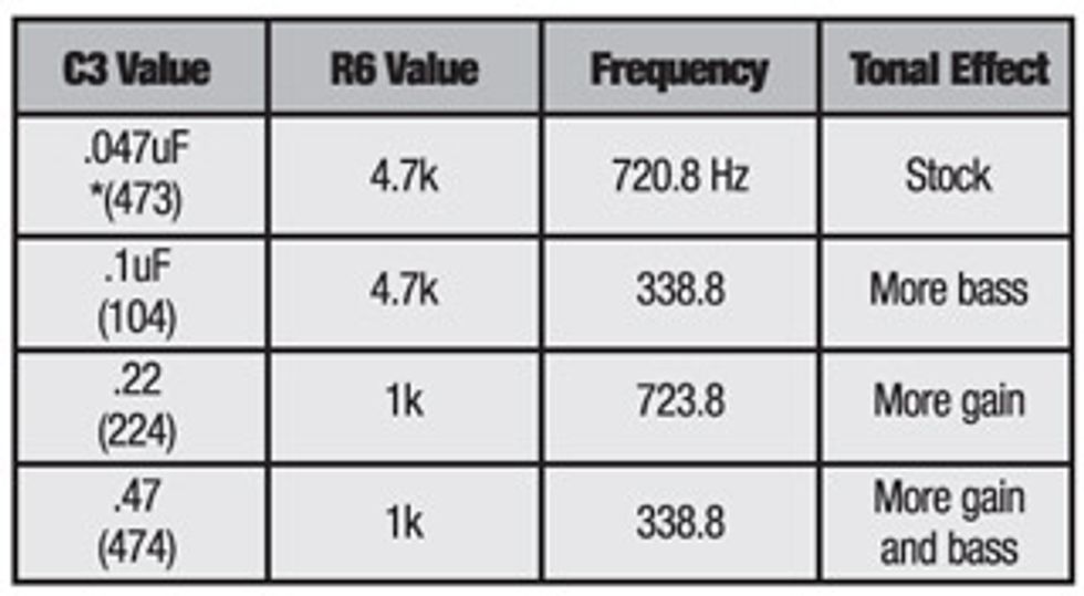
You can adjust the tonality of an SD-1 or a TS9 in many ways simply by using different resistor-and-capacitor combinations for the components in the large oval in Fig. 4 and Fig. 5.
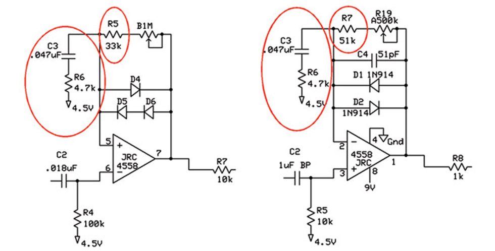
Fig. 4: SD-1 Gain Stage (left). You can achieve myriad tones with a Boss SD-1 by varying the values of the resistor and capacitor shown inside the large oval. Fig. 5: TS9 Gain Stage (right). Altering the values of the resistor and capacitor shown here inside the large oval can yield a wide variety of tones with a Tube Screamer.
This component combination (aka the feedback to ground, or 4.5V in this case) helps set the gain, as well as what frequencies get amplified and clipped by the op-amp (the triangle thingy in the schematic). A stock TS9 is set to clip around 720 Hz. Lowering the value of the resistor will provide more gain, but it will also change what frequency is getting clipped. If you don’t want to change the pedal’s tone, you have to change the capacitor value with the resistor value. You can also squeeze some bass out of the pedal by adjusting the value of the capacitor in this combo. Table 1 shows some values that I suggest you try. If you want to play around with the values and frequencies a bit more, I suggest visiting muzique.com/schem/filter. htm. This website has a great frequency calculator for resistor/ capacitor pairs.
Note: The TS9 and SD-1 are very similar in this part of the schematic, so all of the same mods apply. Just be careful with the SD-1: If you increase the gain too much without adding the proper circuitry, the distorted signal will start to bleed into the bypassed signal. If you run into this problem, you can find mods to rectify the situation online.
Before we jump into the actual mod, let’s look at Figures 4 and 5 again. See the lone circled resistor in each schematic (R5 in the SD-1 circuit, and R7 in the TS9 diagram)? This resistor sets the minimum gain when the drive knob is turned all the way down. I suggest changing it to a 10k Ω in both pedals—it’ll enable them to clean up a lot better.
Okay, let’s replace the SD-1’s R5 resistor, the TS9’s R7 resistor, and the C3 capacitor and R6 resistor in both the Boss and Ibanez pedals.
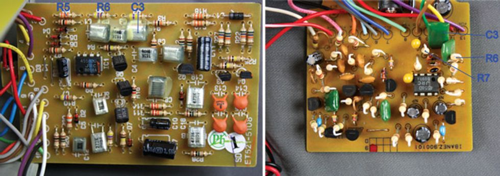
Photo 11 (left): Replacing your Super Overdrive’s R5 resistor with a 10k Ω part will enable you to clean up the signal more. Also, swapping the C3 and R6 components with different values will vary the available gain and which frequencies get amplified and clipped by the op-amp. Photo 12 (right): Swap your Tube Screamer’s R7 resistor with a 10k Ω resistor for a more pristine minimum-gain setting. You can also vary the C3 and R6 values for different levels of drive, as well as to change frequencies the op-amp clips and amplifies.
1. Locate the minimum-gain resistor in your SD-1 (R5 in Photo 11) or TS9 (R7 in Photo 12), desolder it, and solder in a 10k Ω replacement.
2. Then test your pedal.
3. Locate C3 and R6 on your SD-1 or TS9, desolder them, and replace them with different values based on the chart above or perhaps a recipe you come up with using the widget at muzique.com. Note: If you’re modding your SD-1, don’t be afraid to remove the gunk that’s globbed all over C3.
Mod 4: Make Your TS9 or SD-1 More Transparent
Tools and Parts for This Mod
• 1k Ω 1/4-watt resistor (one for a TS9, two for an SD-1)
• A1k Ω audio potentiometer
• .22 μF capacitor
• 2.2 μF electrolytic capacitor
• 1" piece of jumper wire
• Two 3" pieces of wire
• Pot knob for the new pot
Have you ever noticed how, when you turn your TS9’s or SD-1’s tone knob up, it sounds like the pedal is boosting frequencies? That’s because it is. Both pedals have an active tone control. Some players like that, but others prefer a passive tone control. This mod shows you how to install a passive tone control to make your Tube Screamer or Super Overdrive sound much more transparent.
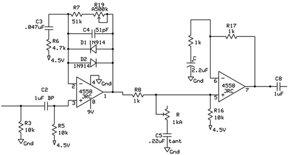
Fig. 6: Schematic for the TS9 and SD-1 transparency mod.
The steps for installing a passive tone control are pretty much the same for a Tube Screamer and a Super Overdrive (see Fig. 6 for a reference schematic), so we’ll cover both together here and note any divergences within the appropriate step.
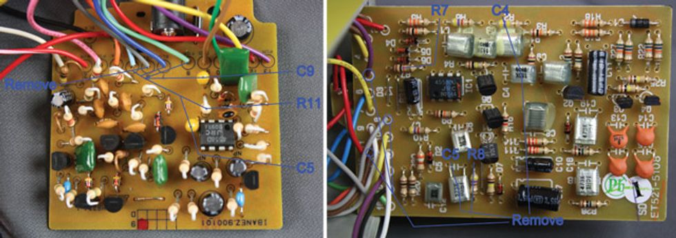
Photo 13 (left): Remove the indicated wires and components in your TS9. Photo 14 (right): Remove the indicated wires and components in your SD-1.
1. For a TS9: Remove wires 6,
7, and 8, as well as components
R11 and C9 (see Photo 13).
For an SD-1: Remove wires 5,
8, and 11, as well as components
C5 and R8 (see Photo 14).
2. Remove the old 20k Ω tone pot.
3. TS9: Attach a 3" wire from
lug 2 of your new A1k Ω pot
to the hole where wire 7 used
to connect to the circuit board.
SD-1: Remove R7 and replace
it with a 1k Ω resistor. Then
solder one end of a 3" wire to
lug 2 of your new A1k Ω pot,
and solder the other end where
wire 5 used to connect to the
circuit board.
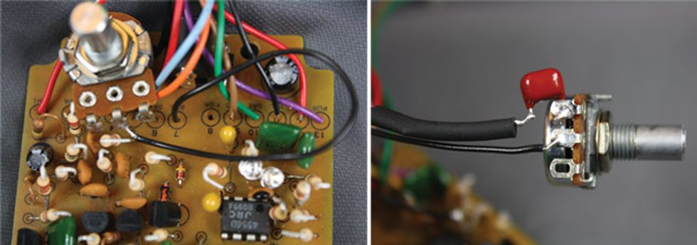
Photo 15 (left): Connect a 3" wire from the new tone pot to hole 7 on your TS9’s circuit board. Photo 16 (right): Solder one leg of the .22 µF cap to lug 1 of the tone pot, then attach a 3" wire to the other leg.
4. TS9: Remove C5.
SD-1: Remove C4.
5. Stick one leg of your new .22 μF capacitor through lug 1 of your new pot and solder it in place. Attach another 3" wire to the open leg of the cap (see Photo 16). Note: When making a connection like this, I suggest stripping a little extra off of the wire and wrapping it around the cap’s leg before soldering it. It’s also a good idea to put electrical tape or heat-shrink wrap around bare spots such as this one.
6. TS9: Solder the other end of
the 3" wire into the negative hole
where C5 used to be (the negative
hole is the one that’s not next
to the plus sign). See Photo 17.
SD-1: Solder the other end of
the 3" wire to the sleeve lug of
the output jack. See Photo 18
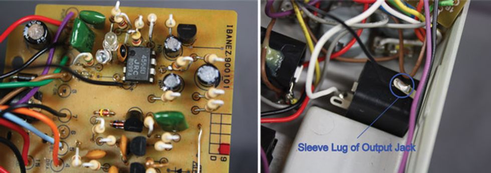
Photo 17 (left): Solder the other end of the 3" wire to the negative hole vacated by C5 in your TS9. Photo 18 (right): Solder the other end of the 3" wire to the sleeve lug of you SD-1’s output jack.
7. TS9: Attach the 1" piece of
wire from where wire 6 used
to be to the hole where wire 8
used to be.
SD-1: Attach the 1" piece of
wire from where wire 8 used to
be to the hole where wire 11
used to be. See Photo 19.
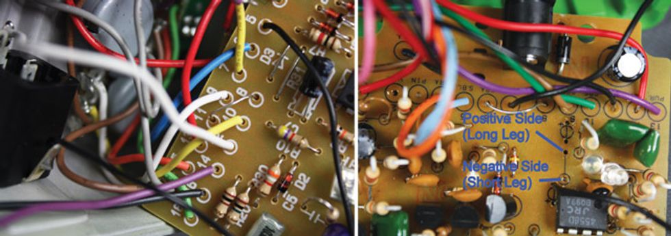
Photo 19: (left): Jumper holes 8 and 11 on your SD-1 circuit board. Photo 20 (right): Install the 1k Ω resistor and 2.2 µF cap in your Tube Screamer.
8. TS9: Solder your new 1k Ω resistor where C9 used to be and place your 2.2 μf electrolytic capacitor where R11 used to be (see Photo 20).
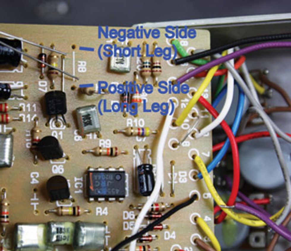
Photo 21: Install the 1k Ω resistor and 2.2 µF cap in your Super Overdrive.
Note: Make sure the negative side of your electrolytic capacitor is closest to your Tube Screamer’s IC chip, and that the positive side is closest to the 1k Ω resistor you just installed. The negative side is usually signified by a stripe on the cap, and the positive side is almost always the long leg.
SD-1: Solder your 1k Ω resistor where C5 used to be and your 2.2 μF electrolytic capacitor where R8 used to be. Note: Make sure the capacitor’s negative side (the short leg or the short leg near the stripe on the cap) is in the hole closest to the edge of the circuit board, and the positive side (the long leg) is closest to the newly placed 1k Ω resistor.Mod 5: Install a Variable Mid Control in Your TS9 or SD-1
Tools and Parts for This Mod
• Two 10k Ω 1/4-watt resistors
• .0068 μF capacitor
• .0047 μF capacitor
• .033 μF capacitor
• B100k Ω alpha single-gang 9 mm right-angle PC mount linear
potentiometer from SmallBearElec.com
• Pot knob
• Three 3" pieces of wire
• 1/4" drill bit
• Marking utensil
• Ruler
Our final mod gives you control over the nasally mids that have long plagued the Tube Screamer and Super Overdrive. Be aware, though, that you’ll lose quite a bit of volume with this mod due to insertion loss. To make up for this volume loss, I recommend you also either replace the original diodes with LEDs or wire the original diodes in series (neither of which is covered here).
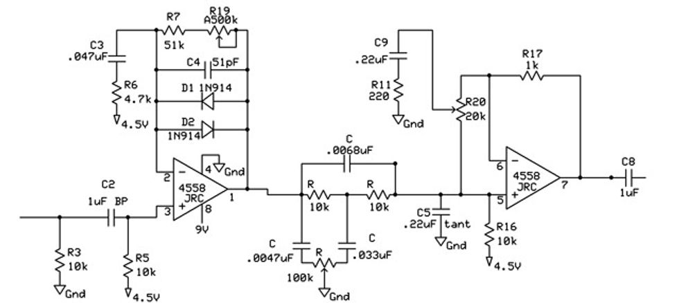
Fig. 7: Reference schematic for the TS9 and SD-1 variable-mid-control mod.
1. TS9: Remove resistor R8.
SD-1: Remove resistor R7.
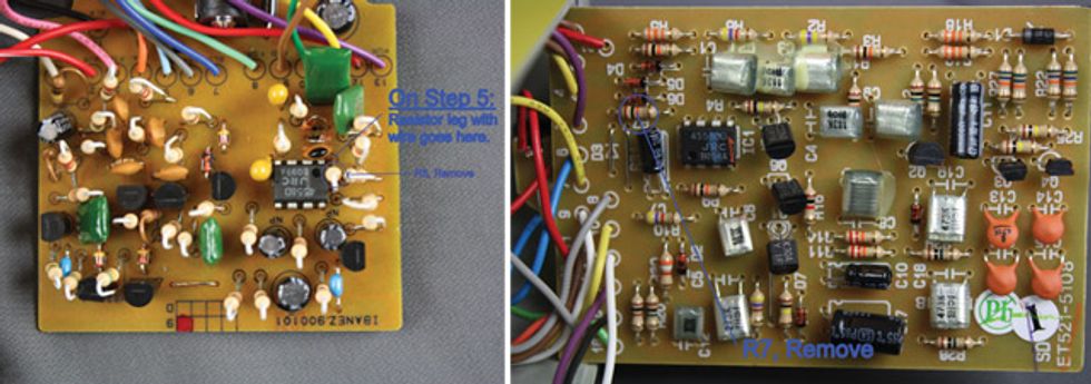
Photo 22 (left): Remove R8 in your Tube Screamer. Photo 23 (right): Remove R7 in your Super Overdrive.
2. Twist one leg from each of the two 10k Ω resistors together so that their bodies are almost touching.
3. Wrap one end of a 3" piece of wire around the connected resistor legs, solder the joint (see Photo 24), and put electrical tape or a heat-shrink tube around the joint (not shown).
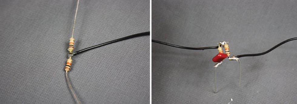
Photo 24 (left): Twist together your 10k Ω resistors and one end of a jumper wire, then solder the joint. Photo 25 (right): Solder your .0068 µF cap to the 10k Ω resistors and attach a jumper to one of the resistors.
4. Twist the legs of your .0068 μF cap onto the long legs of the joined 10k Ω resistors and solder the joint, then twist the end of another 3" wire onto the long leg of one the 10k Ω resistors and solder that connection. See Photo 25.
5. TS9: Place the long leg of the
resistor that has the 3" jumper in
the hole from R8 closest to the
dot (pin 1) on the IC chip. Place
the other resistor’s leg in the hole
vacated by R8. Solder the legs in
place. See Photo 26 and Photo
22, if necessary.
SD-1: Place the long leg of the
resistor that has the 3" jumper
in the vacated R7 hole that is
closest to the IC chip. Place the
other resistor’s leg in the other
vacant R7 hole. Solder the legs
in place. See Photo 27.
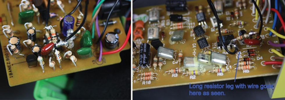
Photo 26 (left): Install the 10k Ω resistor with the 3" jumper in your Tube Screamer. Photo 27 (right): Install the 10k Ω resistor with the 3" jumper in your Super Overdrive.
6. Solder your .033 μF cap to lug 1 of your B100k Ω pot, then solder the last piece of 3" wire to lug 2 of your pot, and then solder the .0047 μF cap to lug 3 of the pot. See Photo 28.
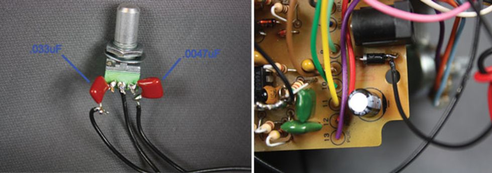
Photo 28 (left): Solder the .033 µF cap, a 3" wire, and the .0047 µF cap to the new pot. Photo 29 (right): Solder the wire from pot lug 2 to the diode near your Tube Screamer’s power jack.
7. Solder the wire attached between the two 10k Ω resistors to the remaining leg of the .033 μF cap that’s soldered to lug 1 of the pot.
8. Solder the remaining wire attached to the long leg of the 10k Ω resistor to the remaining leg of the .0047 μF cap that’s soldered to lug 3 of the pot.
9. TS9: Solder the 3" wire connected to lug 2 of your pot to the leg opposite the stripe of the diode located right next to the power jack (see Photo 29). Test the pedal and be sure that your modifications worked.
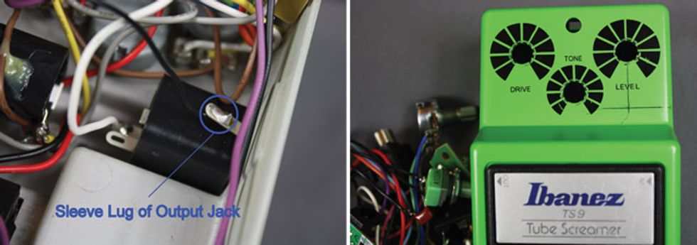
Photo 30 (left): Solder the wire from pot lug 2 to the sleeve of your Super Overdrive’s 1/4" output. Photo 31 (right): Measure and mark the drill hole for your TS9’s new pot.
10. TS9: Measure 5-6 mm
(about 1/4") from the upwardly
angled part of the case and
draw a horizontal line from the
right side of the case to about
where the tone knob is.
SD-1: Measure 1 cm to the right
or left of the edge of the 9V
adapter jack on the front of the
case. Draw a vertical line there.
11. TS9: Draw a vertical
line starting smack dab in the
middle of the volume pot’s hole
until it intersects with the line
you just drew. This will be the
center of the hole for your new
pot (see Photo 31).
SD-1: Draw a horizontal line
1 cm above the bottom of the
case until it intersects with the
vertical line. This will be the
center of the hole for your new
pot (see Photo 32).
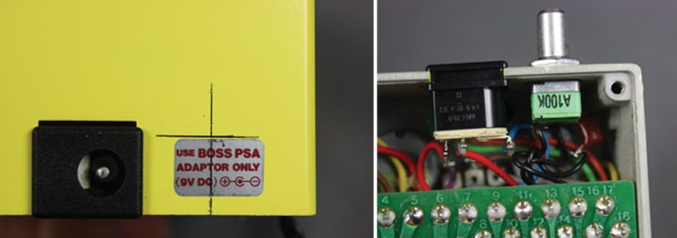
Photo 32 (left): Measure and mark the drill hole for your SD-1’s new pot. Photo 33 (right): Make sure the pot lugs face the top of your Super Overdrive enclosure to avoid shorting the circuit.
12. Drill a 1/4"-diameter hole in the marked spots.
13. Wipe the lines off of the enclosure, secure the new pot, reassemble the pedal, and enjoy your new variable-mid control! Note: On the SD-1, be sure to install your pot so that the lugs face the top of the case so they don’t get grounded to the back plate (see Photo 33).


![Rig Rundown: The Black Crowes’ Rich Robinson [2026]](https://www.premierguitar.com/media-library/youtube.jpg?id=66952027&width=1245&height=700&quality=70&coordinates=0%2C0%2C0%2C0)