If you're a guitar modder, you probably already have most of the simple tools needed for this unique pedalboard project.
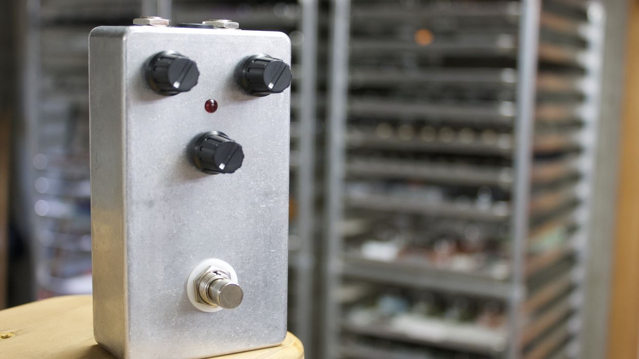
Hello, and welcome to my first DIY project for Premier Guitar. I'm going to explain how to make a battery-operated power supply for your pedalboard (Image 1). We'll be using a cordless drill battery for power and a few other items that you might already have lying around. All of the parts needed for this project can be easily found and purchased online.
Why would you want to use a drill battery to power your effects pedals? By powering your effects with a battery, you eliminate the potential for noise caused by bad wiring in your home or in a venue, it eliminates possible ground loops as well as a cord to trip over, and it expands your possibilities for placement of your pedalboard. Drill batteries are tough, easily rechargeable, and will last a really long time before needing a recharge. They just pop in and out of their charger and will pop in and out of your power supply. If you already have a couple spare batteries, the cost of this build is small. Spare batteries can be purchased online if you already have a charger, or you can even buy batteries and a charger.
If you've been modding the wiring of your guitars, you probably have the tools and skills necessary to build this project.
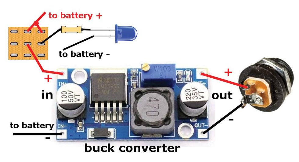
Image 2
You'll need a good soldering iron and solder, a drill, needle-nose pliers, a multimeter, and, of course, eye protection. If you're like me, you'll also need reading glasses to see what you're doing. This build is pretty simple and easy to understand, as you can see in the wiring diagram shown in Image 2. The orange square is the back of the common 3PDT footswitch found in most boutique stompboxes. I used a 3PDT footswitch, but a 2PDT footswitch or any toggle switch will also work for this project.
The two most important items we need, other than a battery, are a battery adapter and a buck converter, sometimes called a voltage converter.
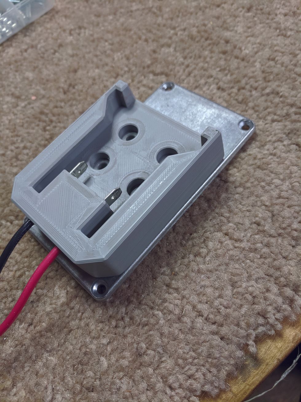
Image 3
The battery plugs into the adapter, just like it plugs into a drill, and has two wires that let us connect to the battery's power. Battery adapters are made for several brands of drill batteries. I use Milwaukee but Makita and DeWalt will also work for this project. I bought my battery adapter (Image 3) for about $16 from Amazon.
The buck converter lets you adjust (or "step down") the voltage coming from the battery to 9 volts, which is the voltage you want for most pedals. These units are also cheap. I bought a pack of four, just in case I ruined one. Get one that will handle at least 25 volts on the upper range and goes down past our target voltage of 9 volts. Also, check how much current it can handle: 3 to 5 amps should be plenty.
Get a buck converter that will handle at least 25 volts on the upper range and goes down past our target voltage of 9 volts.
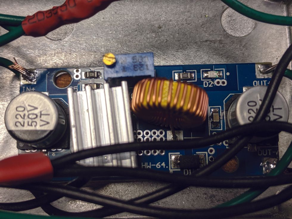
Image 4
The buck converter I bought is about 2" by 1" (Image 4), with connections for DC in and DC out. The small brass screw on top of the blue rectangular box is the adjustment. On mine, turning the screw counterclockwise drops the output voltage. It takes a really small screwdriver to fit the adjustment screw, and a lot of turns to get it down to 9 volts.
The buck converter I bought is good for 3 amps of electric current. So how much current will your pedals draw? I found a good list of different pedals and their power draw on Stinkfoot.se. The four pedals I've been using lately draw a total of 113 mA, or .113 of an amp. It's important to note that stompboxes draw power whenever there is a guitar cord plugged into them, even when switched off. The footswitch on a pedal just routes the signal around the circuitry and doesn't stop the power draw. This is why we're putting a footswitch on our project, so we can turn off the power. We'll also incorporate an LED to remind us when the power is on.
We'll use a basic stompbox enclosure for this project. I used one that measures about 2 1/4" x 4 1/4", and it came in a box of three. The box came with a special stepped drill bit that makes holes for things like jacks, switches, and LEDs, and a helpful list of which steps work for different parts. A piece of masking tape wrapped around the drill bit at the appropriate step will help you drill the right-sized hole without going too far.
What Else Will We Need?
- One 3PDT footswitch (a 2PDT footswitch will also work)
- An LED and mounting bezel
- One 4.7k (drop-down) resistor
- A barrel jack, compatible with your power cord
- Two colors of hookup wire, 22 AWG or 24 AWG
- Standoffs to mount the buck converter, or some silicone caulk
- Three or four nuts and bolts to mount the battery adapter
- And lastly, we will need that old daisy chain power cord I know you have lying around, to power your pedals.
Heat-shrink tubing is not strictly necessary, but it will make your build a lot neater than using electrical tape. Once you buy some, you'll find many uses for it and it'll come in handy often. I got a bag with a bunch of different diameter pieces for a couple bucks, and it's lasted me several years.
Bolt-mount the battery adapter to the bottom of the enclosure.
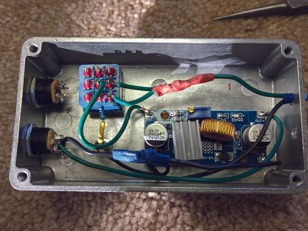
Image 5
Now let's get started. You can see all the parts and wiring fit in the enclosure pretty easily (Image 5). Mark where the holes go carefully. Use the shortest bolts you can, so they don't interfere with the wiring, making sure to leave room to access the screws that hold the enclosure together.
Next, mark where to drill the holes for the footswitch, LED, and jack.
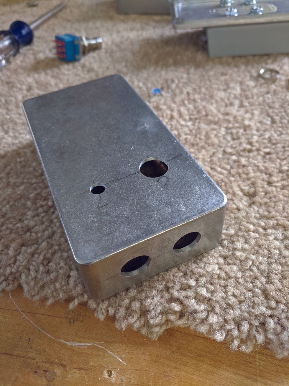
Image 6
You'll need one more hole to bring the wires from the adapter into the enclosure: Put that on the end opposite the jack. Make sure to sand this last hole nice and smooth around the edges so it won't abrade the wire. I put my jack hole about halfway between the top and bottom of the enclosure and that left me plenty of room for wiring. Make sure you leave enough room between the jack and footswitch (Image 6). Now we can mount the jack, footswitch, and LED bezel.
At this point, you just need to follow the diagram to wire things up. I used 22 AWG wire and found it a little bit cumbersome to fit it into a few of the tighter spaces and get it soldered. On that note, 24 AWG wire would probably be fine. It should be good for around 1.4 to 3.5 amps, depending on if it's stranded or solid core. To give you an idea, 1.4 amps is more than 10 times the current of what my four pedals draw.
I mounted another jack for 18-volt output, just in case I ever get an 18-volt pedal. (This would also require a second buck converter.) After wiring it up, however, I found my 18-volt batteries are actually around 20 volts, so I removed the wiring.
If you don't have standoffs for your buck converter, you need another way to mount it to the inside of your enclosure.
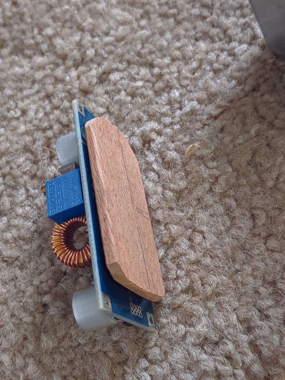
Image 7
I used silicone caulk to glue mine to a thin piece of wood. I used alcohol to clean the enclosure where I put the silicone, to make sure it would stick. After the silicone was dry and I wired up the converter, I used more silicone to glue it to the enclosure (Image 7).
Cut the wires from your battery adapter to a shorter length, feed the wires from the input of your buck converter through their hole in the enclosure, and solder them to the battery wires.
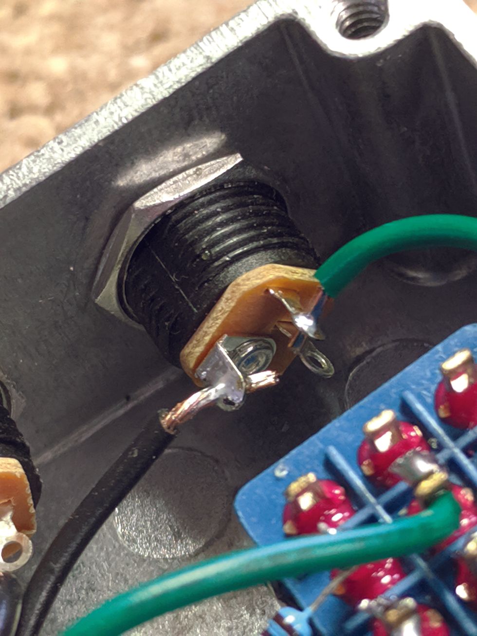
Image 8
This is where your heat-shrink tubing will come in handy. Use some more of that silicone to anchor the wires in the hole after you know everything works. And be sure that you wire your jacks so the center is negative (Image 8).
The LED needs a resistor soldered to the positive leg in series to operate.
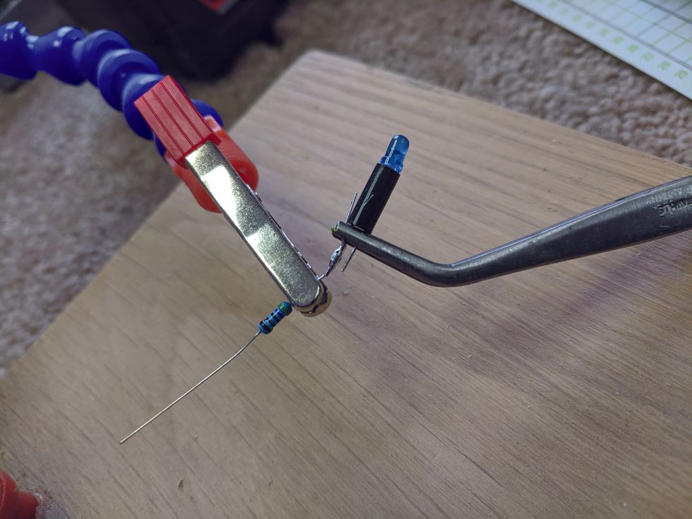
Image 9
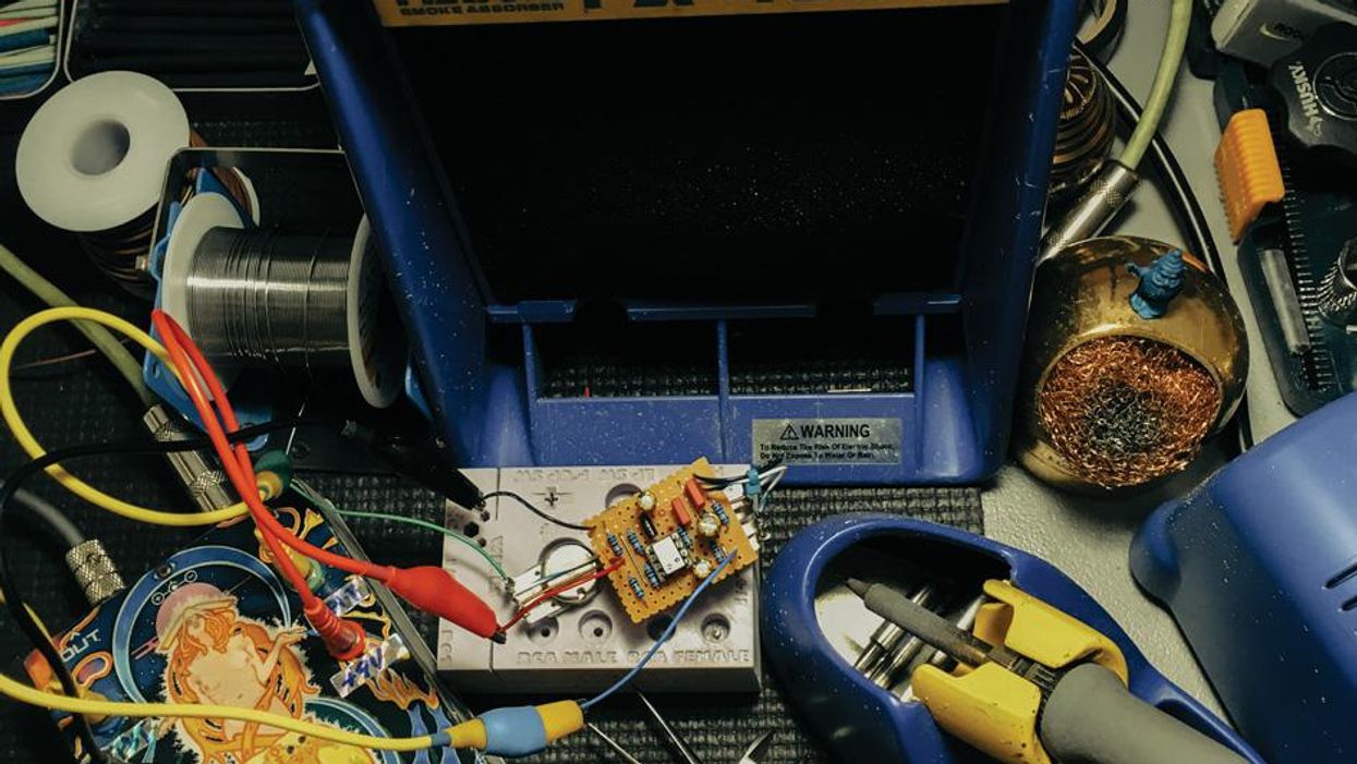
The positive leg is the longer one. Fit the LED legs through the plastic-mounting sleeve that came with the bezel before you solder on your resistor (Image 9). The LED will then just push into the bezel. If your LED is close enough, you can solder the other end of the resistor to the switch, like I did. You can use wire if it's too far. The other lead from the LED goes to the ground from the battery. It's worth noting that the value of the drop-down resistor depends a lot on the type and color or LED. We're using a 4.7k resistor, which works fine with a blue standard LED. For all other LED colors and types, the resistor type can be recalculated online. A good resource for this is: https://www.muzique.com/schem/led.htm.
If you soldered everything up correctly, you should be good to go! I have two different-sized drill batteries, and even the small ones will power my pedals for nine hours. I would suggest turning your power supply on and testing with your multimeter before plugging in any of your pedals, taking care that the polarity of your output is correct.
How could you modify my design? You could use a larger enclosure and more jacks, allowing you to power each pedal with its own cable. Instead of a larger enclosure, you could make a separate box with lots of power jacks. A second buck converter could allow for 18-volt power. Maybe it would make sense for you to mount your battery adapter directly to your pedalboard and mount the stompbox enclosure separately. Let me know if you have other ideas in the comments section online.
For me, this was an enjoyable switch from my usual projects. I have a lot of leftover parts, so I guess it's time to start thinking about what to make next.PQ: "I would suggest turning your power supply on and testing with your multimeter before plugging in any of your pedals, taking care that the polarity of your output is correct."
[Updated 1/25/22]
- Powering Your Board - Premier Guitar | The best guitar and bass ... ›
- Tools for the Task: Pedalboard Power - Premier Guitar | The best ... ›
- Got Noise Issues? It Could Be Your Pedalboard's Power Supply ... ›
- DIY Pedalboard Build - Premier Guitar ›
- Got Noise Issues? It Could Be Your Pedalboard's Power Supply - Premier Guitar ›
- Powering Your Board - Premier Guitar ›
- Tools for the Task: Pedalboard Power Supplies - Premier Guitar ›
- The Power of a Good Supply: Pedalboard Power Supplies ›
- Voltage Cable Co. Unveils New Vintage Coil Cables - Premier Guitar ›
- Revolutionize Your Tone with Static Effectors Street Series - Premier Guitar ›
Fender’s Jack White Collection dropped this week, and it includes what might be the most exciting tube amp design in decades. Fender’s Stan Cotey shares some firsthand insight into this unique amp’s design.
This week, Fender and Jack White dropped a new line that spun heads across the guitar-gear universe, proving that the Third Man’s brain knows no bounds. White has been blowing minds with Third Man Hardware’s line of collaboratively conceived gear. Working with makers of all sizes, each yellow-and-black piece is as unique as White himself.
Hooking up with Fender for the Jack White Signature Collection—which includes the Signature model hot-rod Jack White TripleCaster Telecaster and the stunning Jack White TripleSonic Acoustasonic—is as big as it gets, and this week’s announcement is proportionately epic.
The all-new Jack White Pano Verb amp looks to be one of the most forward-thinking advances in tube amps we’ve seen in … well, a very long time! Although it’s roughly inspired by three vintage Fender models—a 1964 Vibroverb, a 1960 Vibrasonic, and a 1993 Vibro-King—the Pano Verb is a rare all-new design that is poised to thrill. The single-channel stereo amp delivers 70 watts of combined power and features stereo harmonic tremolo and stereo reverb circuits, with unique routing options through the hip pair of 15" and 10" speakers. If you haven’t checked out Fender’s video announcing the amp, prepare to have your mind blown by the possibilities.
“It wasn’t based on what we could or couldn’t do, or what even was or wasn’t possible. It was just what Jack was looking to accomplish.”
Fender Vice President of Research and Development Stan Cotey, who worked closely with White to develop the prototypes for the Pano Verb, says, “There were no restrictions as far as how wild something could be. It wasn’t based on what we could or couldn’t do or what even was or wasn’t possible. It was just what Jack was looking to accomplish.” Putting those goals into action was a kick for Cotey. “I love the fact that we’re still pushing the idea of vacuum tubes and that there are things remaining to be done,” he says. “And [the Pano Verb] is a really crazy thing. It’s fun when one of the larger companies tackles a big crazy thing and releases it in a bold manner.”
We rang up Cotey to get the scoop on designing the amp as we wait to get our hands on one.
Cotey calls the Pano Verb “a really crazy thing,” and says, “It’s fun when one of the larger companies tackles a big crazy thing and releases it in a bold manner.”
The Pano Verb has a refreshingly unique and adventurous set of features.
Stan Cotey: There’s two separate power amps, there’s two separate preamps, there’s a reverb circuit. There are two separate harmonic vibrato circuits. There’s two full, separate amps in it—there’s one power supply, but everything else, there’s at least two of.
There are several different kinds of stereo interaction that could happen. The harmonic vibrato could be stereo. The reverb, even though it’s a mono tank, could be steered to the speakers differently, which kind of gives a stereo-imaging thing. So, that opens up myriad possibilities for how things could work.
How involved was Jack in the design?
Cotey: He was completely hardcore. He cared in great detail, exactly down to fine decimal points, how it worked. He was very particular about the voicing. He was very particular about the features he knew. He’s pretty studio savvy, so he had a sense of routing, how he wanted the stereo interaction of the sections to work together. He very much had an idea of stereo-ness for the amp at the outset of it. He talked early on about miking both speakers and panning them—he wanted to be able to do sort of startling things with each speaker’s content.
I think my role was to take the stuff that he wanted to do and figure out how we could do it. So, the stereo-ness of the amp, the 10" speaker versus the 15" speaker, the routing stuff you could do where the reverb goes to one speaker or both, all that stuff came from Jack.
Jack’s Vibrasonic was a touchstone for the Pano Verb.
Cotey: That amp lived with me for quite a while. He knew that he liked the harmonic tremolo.
The stereo harmonic tremolo, that’s a fairly part-intensive circuit, even in a normal brown amp. In this amp, there’s two full circuits in it, so it is literally double the parts of one of the more complicated earlier ’60s amps, just for that part of the amp. I worked out how that works. That’s two harmonic tremolos that are in sync, but opposite polarity. So, when one’s going up, the other is going down, and vice versa.
Stan Cotey is Fender’s Vice President of Guitar Research and Development and worked with White to design the prototypes for the Pano Verb.
The reverb mix on the Pano Verb is rooted in some vintage designs, but it’s handled a little differently here.
Cotey: In the video, he talked about the reverb tank in front of the amp, which forms the Vibro-King, and that he liked the idea. I think he liked the idea of having a more comprehensive, dedicated reverb circuit in an amp, not where it’s just kind of spread on the top, like margarine or something.
In a traditional Fender amp, there’s a feed that comes off the preamp circuit that goes to a driver, which is a tube and a little transformer, and that drives the reverb tank. Then, the output of the reverb tank goes into a recovery amp, a little gain stage with a tube, and that gets mixed with the output of the channel and shoved into the power amp. So, the reverb kind of occurs between the preamp and the power amp. It largely takes the tonality of the preamp on because the tone controls are upstream of it.
Jack has an old Fender amp from the early ’60s that had reverb added. I don’t know who modified it, but they actually used the second channel of the amp as the reverb return, which I think is really super clever. Then you get tone controls for the reverb. So that’s where that idea came from. He didn’t necessarily want the reverb circuit in front. He liked it between the preamp and the power amp, but he wanted to have it be more comprehensive than what would be on a typical mid-’60s Fender amplifier.
What was the most exciting feature for you to create?
The stereo harmonic tremolo was really fun, and the journey that we went on to get there was really cool. I have a tweed amp from the late ’50s from Guild that has tremolo in it, and it’s a stereo amp. It has two separate everythings. The tremolo only works on one side, and that gives the apparent sound that it’s kind of going back and forth between the speakers. We tried having just the harmonic tremolo on one side of this, and it really wanted to have two complete full circuits. So that was one of the changes that got made.
Getting the power amps to work well together was fun too. That was more about transformer and tube selection and working the power supply parts out, getting the amps where they would distort in the right way at the right times or right level. But the harmonic tremolo was definitely the elephant dancing on the bucket with the streamers going off.
Creative Commons: https://creativecommons.org/licenses/by-sa/2.0/
It’s a common misconception that Nashville, my adopted hometown, got its Music City nickname because of the country music industry. It was actually inspired by the Fisk Jubilee Singers, the Grammy-winning gospel-vocal powerhouse from Fisk University that was formed in 1871 and toured the U.S. and Britain over the next two years. As the story goes, Queen Victoria declared that Nashville must be a “city of music” to spawn such a glorious ensemble.
But there’s more to the tale. From 1935 to 1965, Nashville was arguably the epicenter of Black American music. Along the 30 blocks straddling Jefferson Street—Nashville’s own “Black Wall Street”—were a host of clubs, including Club Baron, Club Stealaway, the Del Morocco, and the Black Diamond, that showcased live music from 7 p.m. until 3 a.m. every weekend. And the roster of talent included a who’s who of national acts—Count Basie, Ray Charles, Ike & Tina Turner, B.B. King, Otis Redding, Etta James, Little Richard, Hank Crawford, James Brown—and formidable locals like Johnny “Blues Boy” Terrell, Gene Allison, Jimmy Church, Marion James, Charles “Wigg” Walker, Frank Howard, and two highly notable guitarists: Johnny Jones, the big dog of Nashville rhythm & blues guitar, and young upstart Jimi Hendrix.
But there’s stillmore to the story. In 1946, Nashville’s WLAC became the first major radio station to play R&B records, defying the city fathers and Jim Crow. Its signal reached 28 states and three Canadian provinces, making WLAC the platform by which Black music was introduced to the mainstream. WLAC’s impact on the sales of the indie labels recording Black artists at the time was tremendous.
Not only that. In 1964, Night Train, filmed at WLAC-TV, became the first syndicated R&B television show. Hosted and programmed by Noble Blackwell (who would eventually have an influential career in radio), and with an all-Black cast, Night Train featured local and national acts, and was the template for Soul Train.
Lorenzo Washington is the founder, guide, and curator of the Jefferson Street Sound Museum, where he provides a living introduction to the Black-music culture that first defined Music City.
“A host of clubs, including Club Baron, Club Stealaway, the Del Morocco, and the Black Diamond, showcased live music from 7 p.m. until 3 a.m. every weekend.”
After two years, pressure from the owners of the Grand Ole Opry caused WLAC’s owners to cancel Night Train, which the Opry perceived as a threat to ticket sales, according to Blackwell’s widow, Katie, and performers Church and Howard. And the radio station’s new management also pulled the plug on its R&B programming. At the same time, Nashville’s establishment—which had long waged a cultural war against the Black community along Jefferson Street—managed the coup de grâce they’d sought for decades by redlining and constructing Interstate 40 through the heart of Jefferson, where bridge abutments now mark the location of some of these historic clubs.
Today, most of the entertainers, DJs, and entrepreneurs responsible for Nashville’s—and therefore, in part, the nation’s—R&B revolution are dead, although on a lucky night you can still hear Walker, Church, or Howard turn back time onstage. But all of those memories and as much history as you can fit into the ground floor of a small house can be found at the Jefferson Street Sound Museum. For the past 23 years, the Museum at 2004 Jefferson has been the passion project of Lorenzo Washington. He secured the building in 2011 for a studio, but a year later felt a calling to create a temple dedicated to preserving Jefferson Street’s musical legacy—an urgency amplified as the local players who were there expired.
When you go to the Jefferson Street Sound Museum, you’ll find plenty of artifacts, from period-correct guitars to the old WLAC broadcast board, and handbills, posters, autographed photos, and ephemera. But the most important exhibit is Lorenzo. Beginning in the late 1950s, he was on the scene, as a fan and friend to the musicians, and even as a driver for songwriter and producer Ted Jarrett.
At 81, Lorenzo’s memory and storytelling skills are exquisite. Warm-hearted and welcoming, he can talk about Hendrix’s days as a maverick in the world of straight R&B, of the menus served while the musicians entertained, of B.B. King driving dancers to a frenzy, and even about the Nashville Stars, the city’s beloved Negro League baseball team that was bankrolled by Sou Bridgeforth, a numbers operator and the owner of the New Era Club, where Etta James recorded her blazing Rocks the House album in 1963. For his work preserving Music City’s foundational music culture, Lorenzo has been honored by the city with Lorenzo Washington Day and is the subject of a living legends exhibit at the National Museum of African American Music (NMAAM) in downtown Nashville.
So, if you’re coming to Nashville, you’ll want to visit Broadway, and the big attractions like the Country Music Hall of Fame and Museum and NMAMM. But if you really want to learn about the roots of Music City, go to 2004 Jefferson Street, and have a conversation with history.
A reimagined classic S-style guitar with Fishman Greg Koch Signature pickups and a Wilkinson VS100N tremolo.
Designed to resonate with both tone and soul, this guitar boasts a slightly larger profile with a raised center section, offering superior dynamics and feel. A chamber beneath the pickguard enhances punch, while hum-free Fishman Greg Koch Signature Gristle-Tone pickups and a Wilkinson VS100N tremolo complete the package.
This marks the third signature model from Reverend Guitars for blues virtuoso Greg Koch, joining the revered Gristlemaster and Gristle-90. Each of these guitars, equipped with Fishman’s Greg Koch Signature pickups, embodies the relentless pursuit of tone, delivering inspiration to players who seek to push their own musical boundaries.
The Gristle ST has everything I need to engage in fiendish musical deeds. It has the classic sounds with a second voice to the pickups that adds more girthsome tones, a tremolo system that can take a licking and stay in tune, it’s a gorgeous looking and playing instrument that is just a little bit larger as to not look like a mandolin when played by a larger soul such as myself…I can dig it all! – Greg Koch
The Reverend Greg Koch Gristle ST is now available through any Reverend Authorized Dealer.
For more information, please visit reverendguitars.com.
Nashville's historic Gruhn Guitars give PG an exclusive look at a very early amp that is a piece of rock history that preceded the heralded JTM45. Amp builder and reverb aficionado Eric Borash of Ebo Sounds shares his expertise on this rare amp's lineage, while John Bohlinger plugs in Dan Auerbach's old '60s ES-335 to test it out.